Rear Suspension Model
Rear Suspension Model
Aim
- Open and check the geometry and perform geometry cleanup.
- mid-surfacing for required geometry using different techniques or by implementing various ways.
- Defining the quality criteria for the shell mesh generation.
- Meshing using best and batch mesh button in ANSA.
- Assign required individual surfaces its thickness.
- For tetra mesh, create the property ID to store volume mesh.
- Set proper growth rate and generate tetra (unstructured) mesh.
- Clear all the joins from the mesh by keeping it as it is and release it from geometry.
- Fix the quality of elements.
- Provide connection to the model with respect to their function and movement.
- Identify and convert 1D element.
- Convert shell mesh to solid mesh.
- Lastly, write report on eachshell and tetra meshing, connection for car suspension model.
Objective
- Open the model in ANSA and perform topology and assign proper orientation to the geometry.
- Perform geometry cleanup.
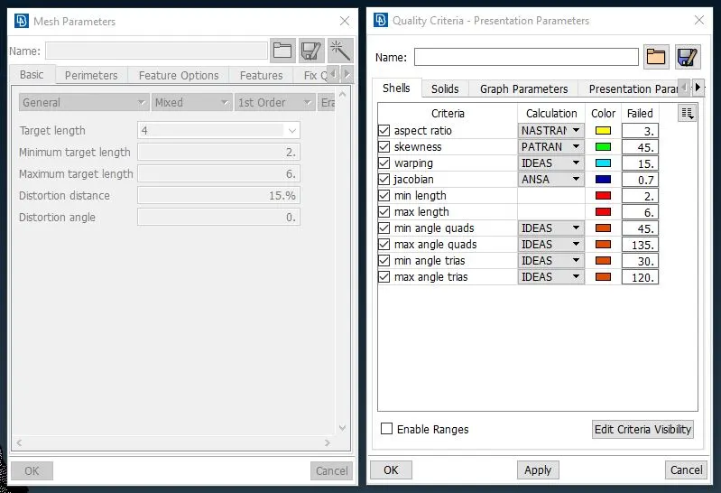
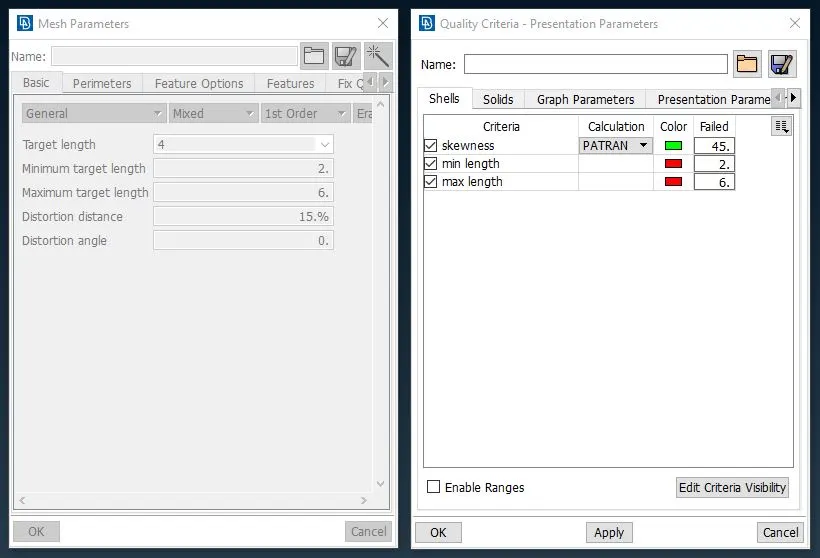
- Assign expected quality criteria in order to maintain mesh quality. Also provide average length of mesh elements with minimum and maximum length.
- Defeature all features that have length less than our minimum length quality criteria.
- Provide separate Property ID to every part for easy observation and fast handling.
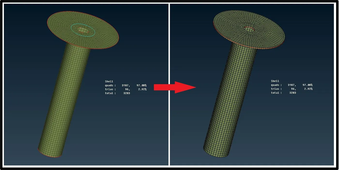
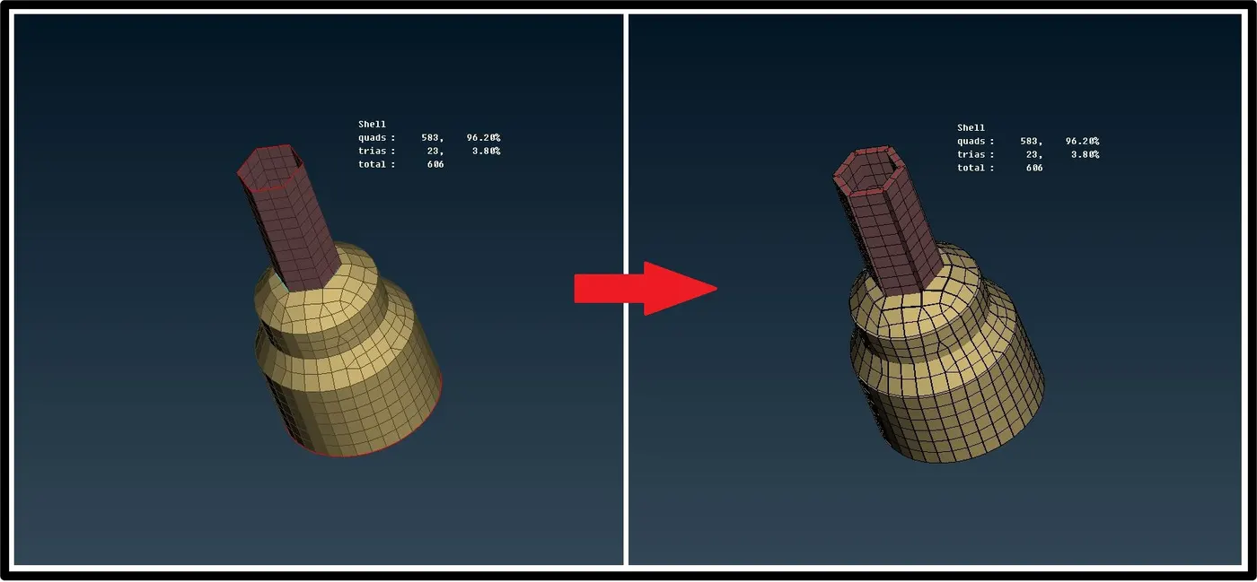
- For shell meshing, Generate mesh using best and batch mesh command and reconstruct it to reduce number of tria elements. Then smooth it using smooth button.
- Give proper thickness to each mid-surface in element property section.
- check mesh if there any elements not fitting under our quality criteria and correct it using split and join element button.
- Finally, clear all the joins from the geometry by keeping same element structure and release all the element from geometry.
- For solid or volume meshing, Generate mesh using tiraand ortho tria mesh command and reconstruct it to correct mesh quality criteria. Then smooth it using smooth button.
- Set new volume Property ID for the enclosed region to store volume mesh in it.
- check mesh if there any elements not fitting under our quality criteria and correct it using reconstruct and fix mesh button.
- Finally,save all the tetra mesh volume and prepare a report on the procedure.
- Observe model and find out the area where connection is needed.
- According to working or movement connect all the are one by one using proper connection technique from ANSA toolbar.
- Find if there any element that can be convert into 1 d element and convert it.
- Convert shell mesh to 2d solid mesh.
Import Model:-
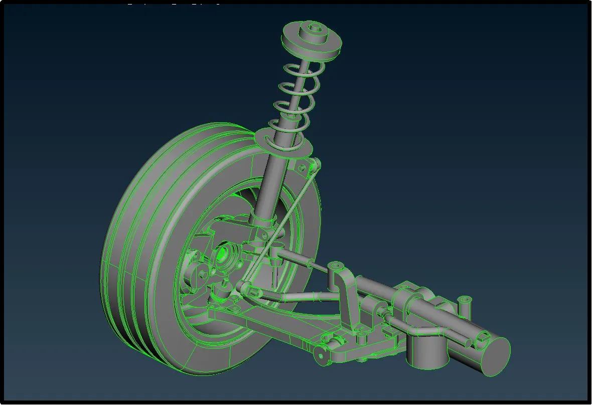
In this project our first step will be importing the ”.ansa” model in ANSA. We can do in by drag and drop method or using open option from file menu in ANSA. After, we open the model, it will look something like this.
Geometrical Topology and Orientation:-
After importing the geometry, when we import .igs file, we always perform topology on geometry to join all the edges of the surfaces and latter we give proper orientation to each surface. But, in this case, geometry is well oriented and topologically correct so we are going to skip this task.
Geometry cleanup:-
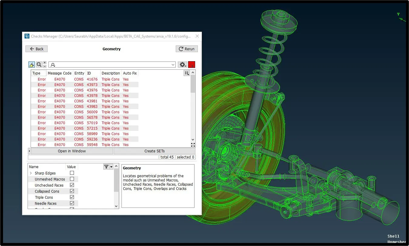
Next part is to preform geometry cleanup to remove unwanted surface, cons from geometry for smooth transition of mesh from each faces. Do it by using fix option and if still some aria need cleanup then solve that fix manually. in given geometry we will clear the tipple cons by separating each part.
Set Property ID:-
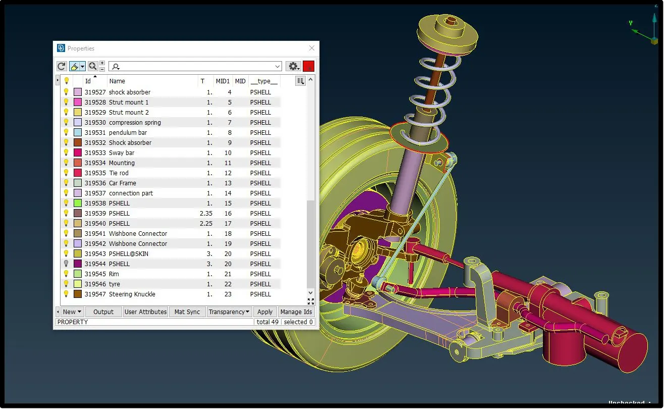
There are plethora different parts which is assign to same Property ID which is hectic for any user to find or identify different parts because of same color. So our first task should be to assign different property IDs to each individual parts. By doing this, firstly, we can see each part with their unique color, better to identification of various part. Secondly, separate PIDs latter help us to assign different thickness to every parts.
Mid-surfacing:-
Now, we can extract mid surface from faces of the geometry one by one according to different thickness of individual section we will assign thickness to its property. In order to extract surface we can use manually we can use various method like offset, middle (single or multi) from faces option, we can also create middle curve by using middle button in curve section and then after create surface using those curves.
Following plate have uniform thickness, therefore we can directly extract mid-surface using skin option.
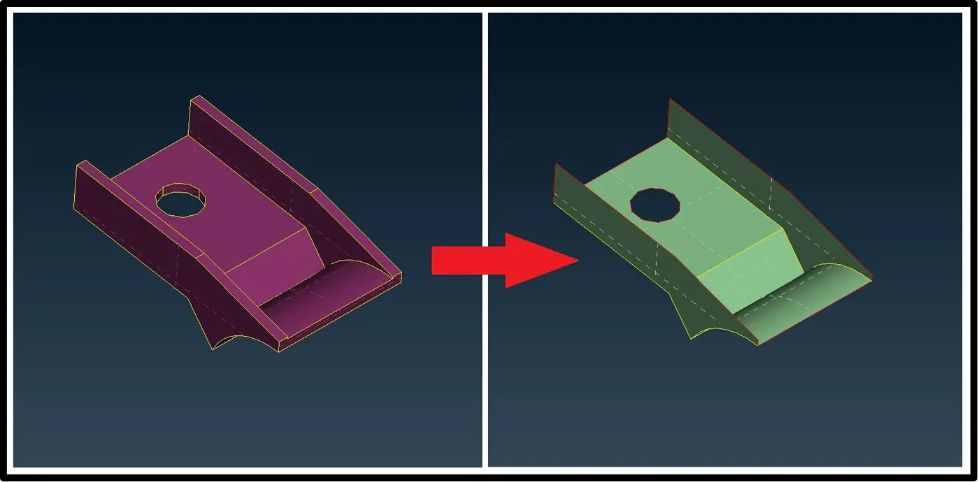
For below part, use offset option and we have to perform little geometry cleanup to get proper surfaces.
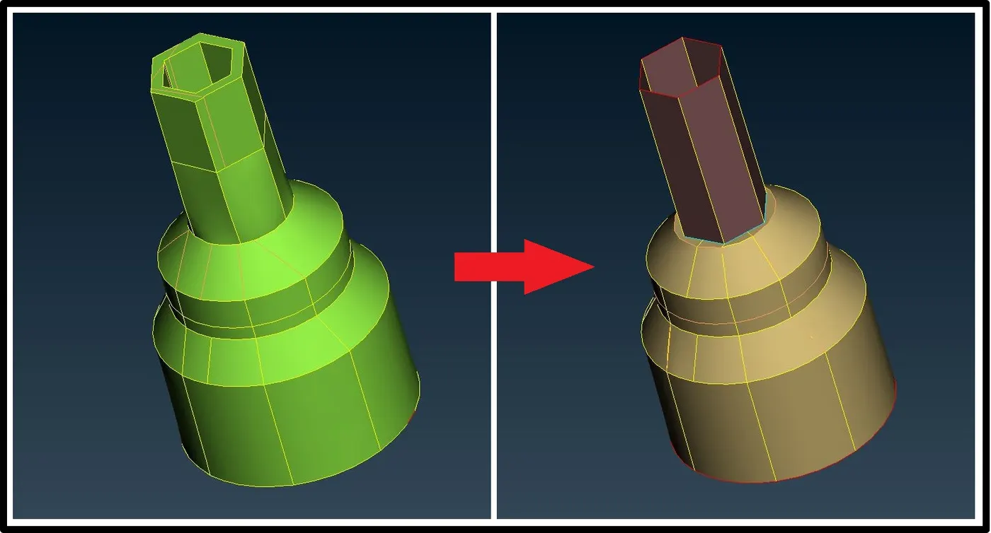
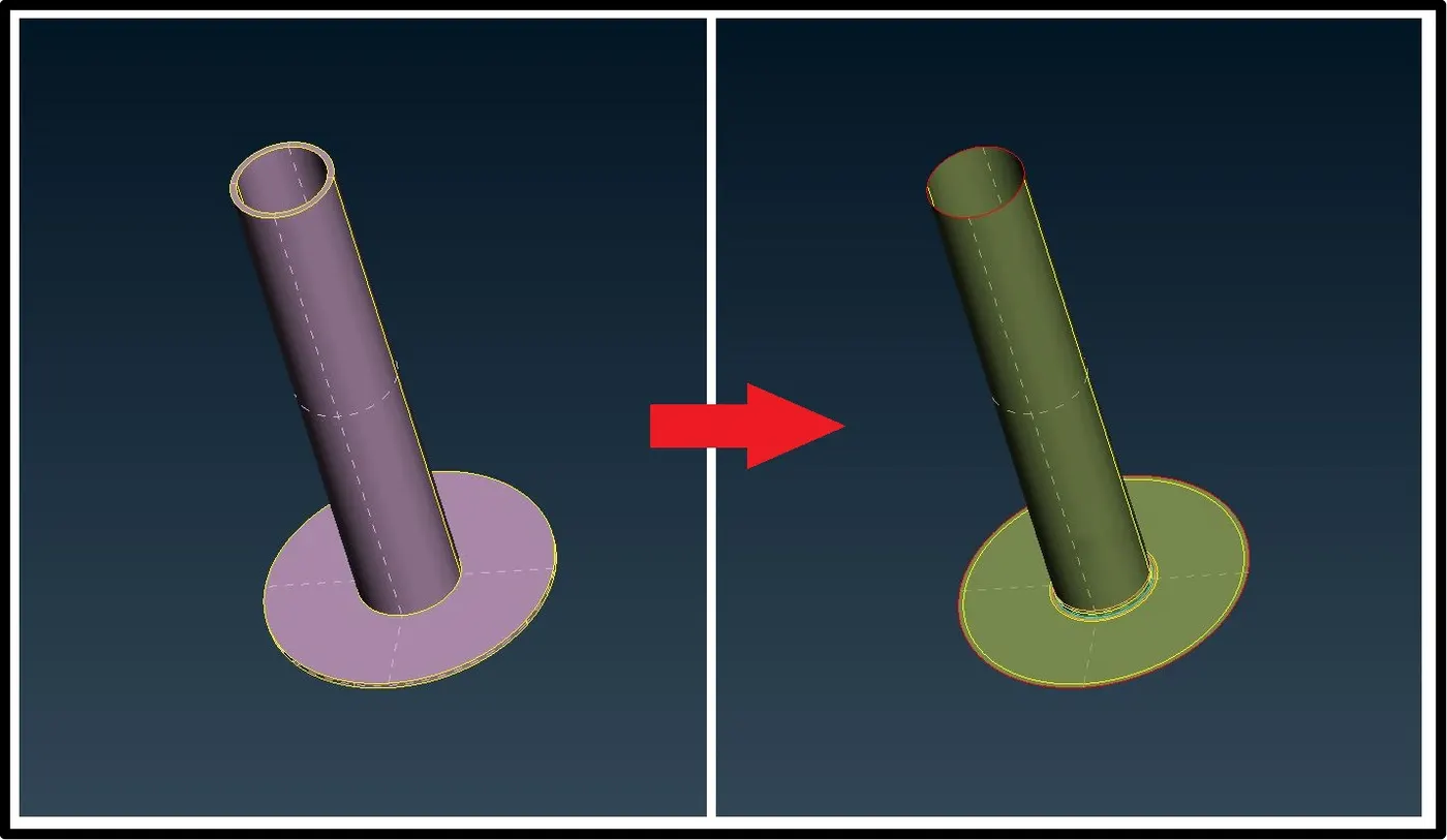
last part that we can use as 2d meshing is shock absorber cylinder. Use direct offset option to extract mid-surface from it.
Quality criteria for shell meshing:-
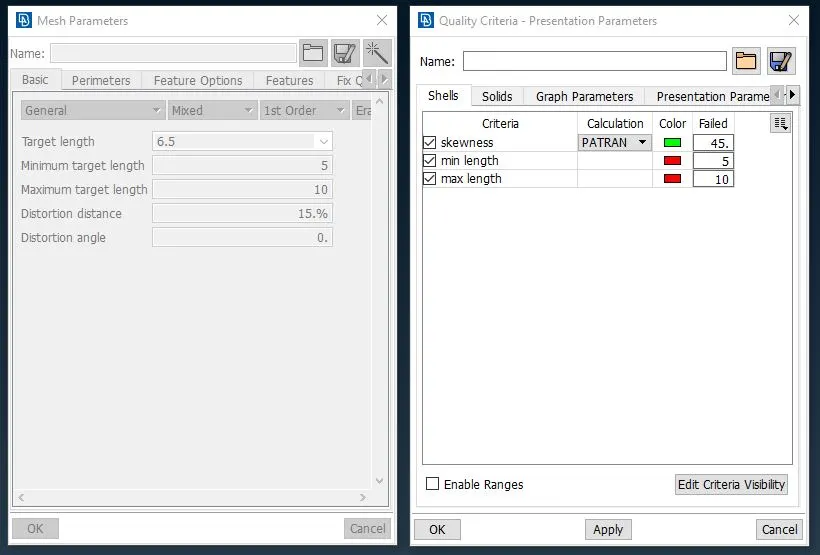
Now, our next step is to provide quality criteria for the solid and shell meshing. For this model our quality criteria is put in ANSA as per given below.
Shell meshing:-
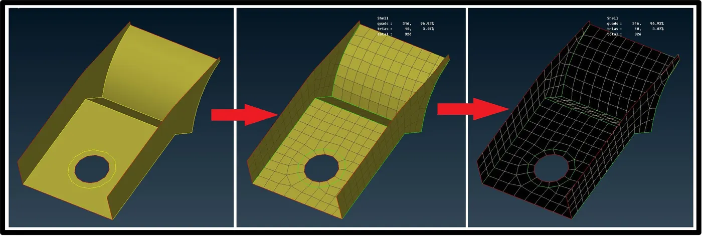
Now, we can mesh our extracted surfaces using best and batch mesh button.
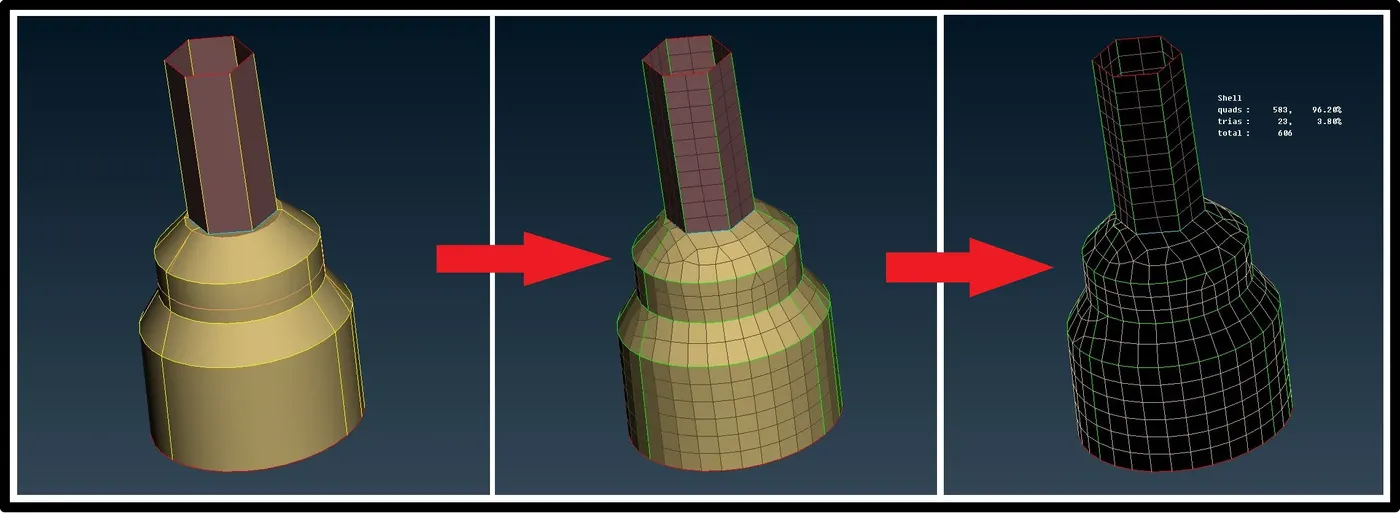
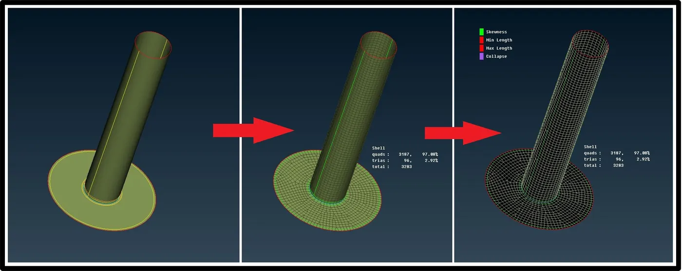
First, mesh all the connected surface and clean that mesh using split, join, smooth, reconstruct option and then mesh base surface by hiding other mesh. In a bid to rearrange and remove tria elements we will use reconstruct button and select the button that we have to rearrange. Latter we are going to smooth it. for 2d meshing we are going to deploy mixed type of mesh.
Quality criteria for tetra shell meshing:-
Tetra shell meshing:
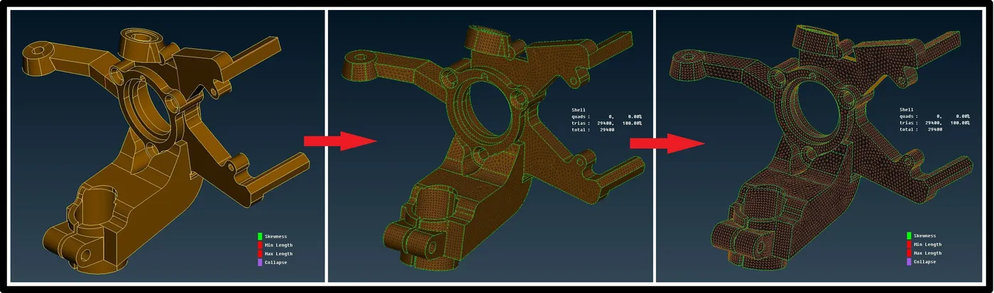
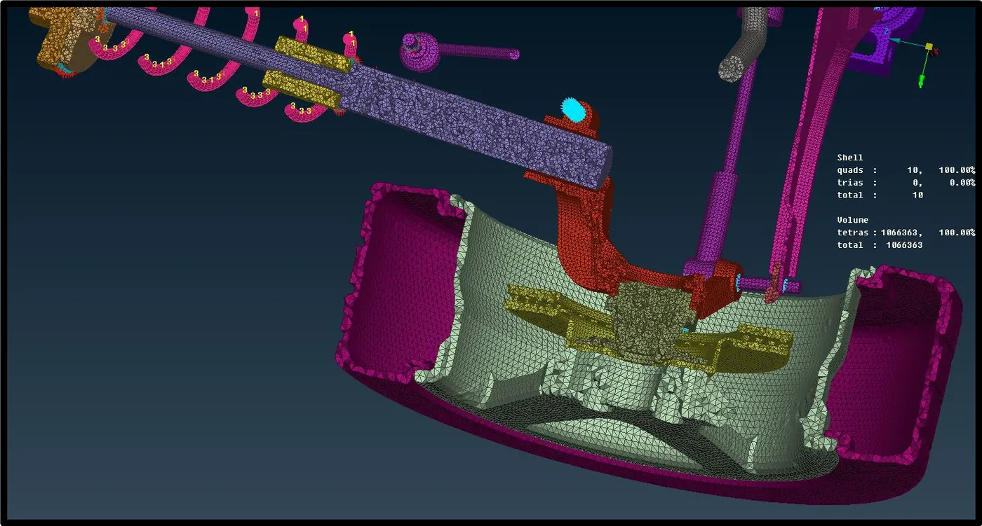
Now , we can start meshing. In order to generate solid/volume mesh we have to perform enclose shell mesh to each part of the model one by one. Therefore, firstly, perform shell mesh using spot mesh button and generate tria and ortho tria mesh with respect to the surface, in case of element failure perform reconstruct and smooth operation on mesh.
Spot mesh: This function automatically meshes Macro and FE shell mesh areas using a special meshing method for Macro-Areas that have 'weld spot' nodes on their surface.
The Spot Mesh algorithm gives better results than the free meshing method and creates the optimum number of shell elements, taking into account the element type already selected and the defined meshing parameters.
The function may be applied to selected unmeshed Macros, or to all visible Macros according to the chosen option (Selected or Visible respectively). The Re-Generate option applied to selected Macro Areas where, firstly, erases existing mesh, if any, and secondly meshes them using the Spot Mesh algorithm. The resulting shell elements are of first or second order shell elements according to the status of the 2nd Ord flag.
Steering Knuckle:-
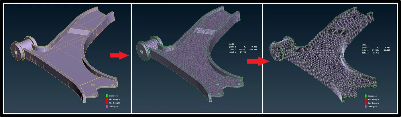
Wishbone Connector:-
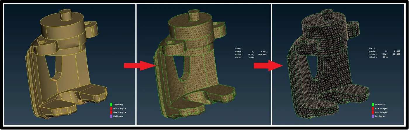
Brake Caliper:-
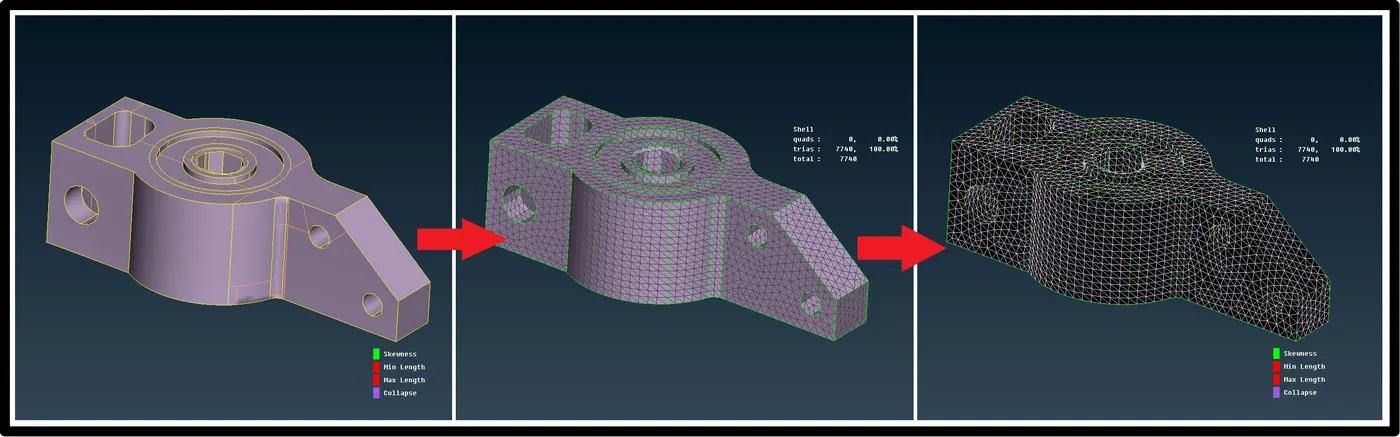
connection part:-
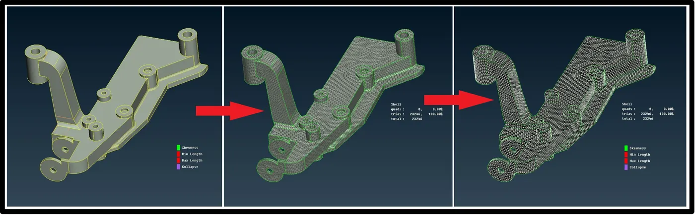
Car Frame:-
Tie rod:-
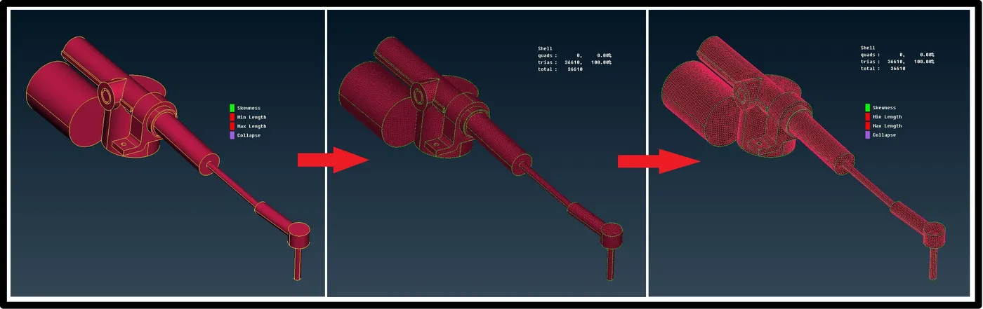
Mounting:-
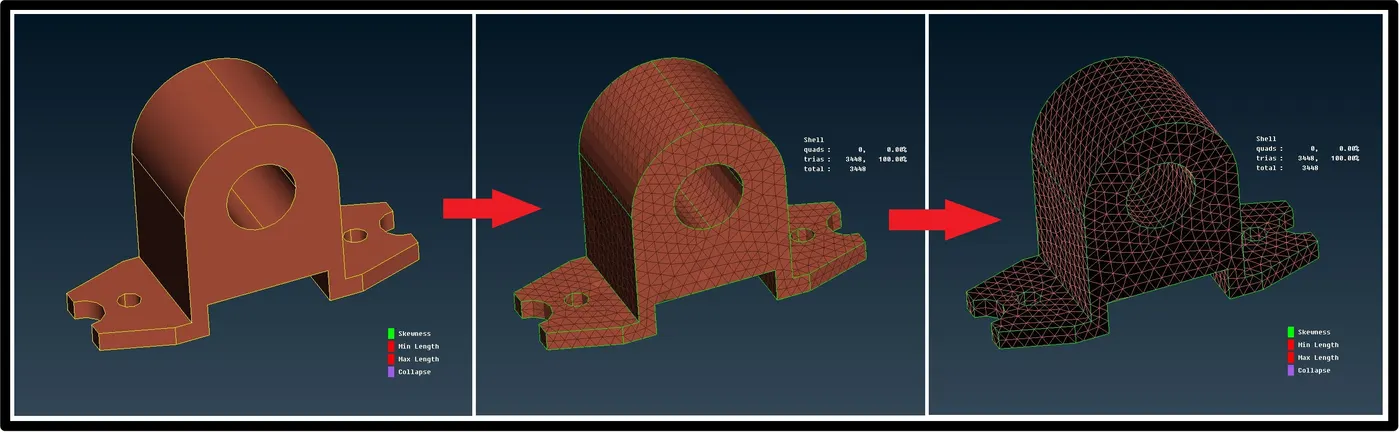
Sway bar:-
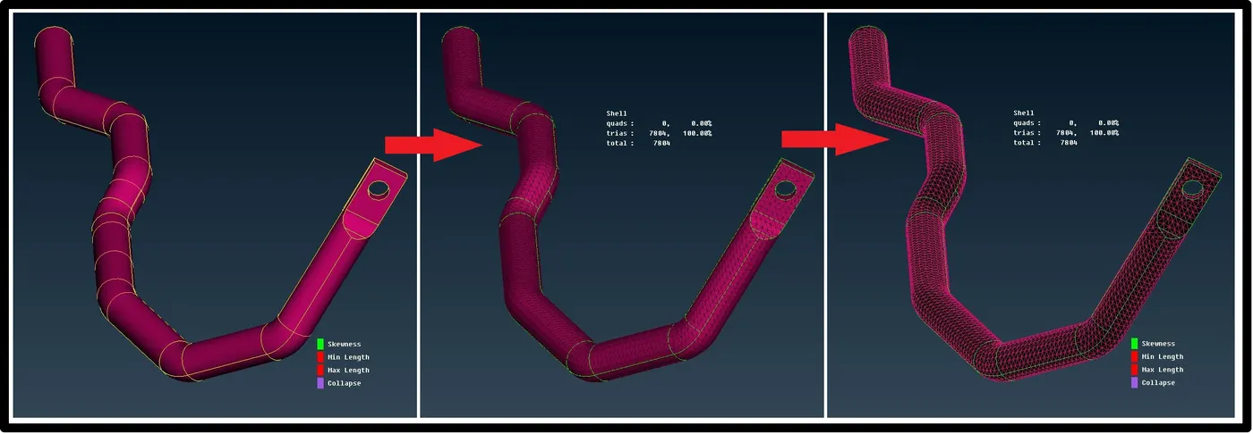
Shock absorber:-
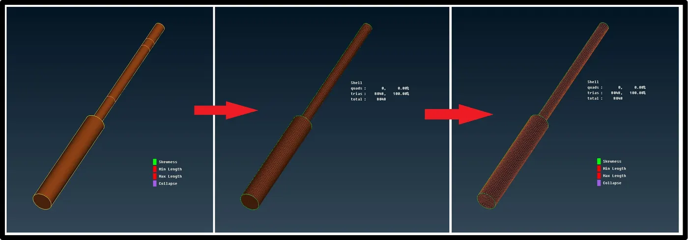
pendulum bar:-
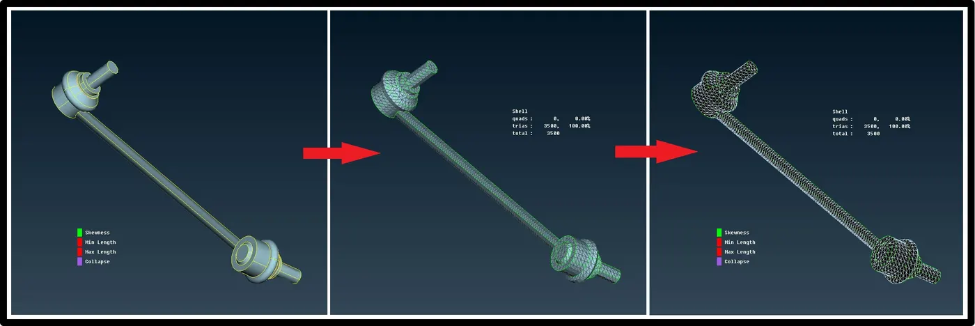
Strut mount 1:-
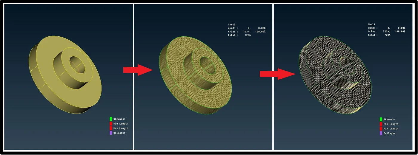
Strut mount 2:-
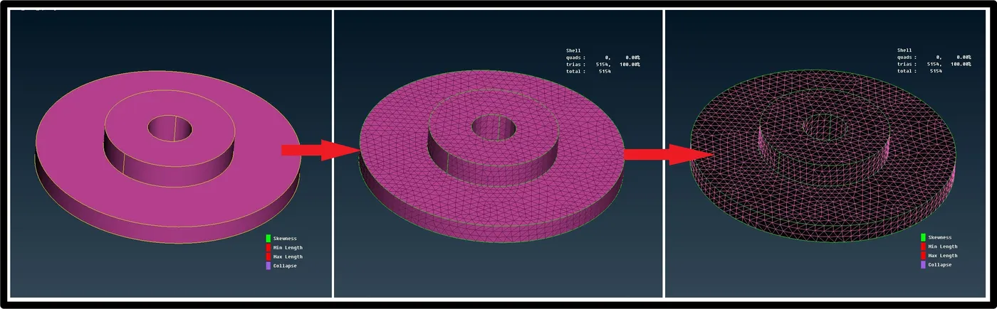
Bush:-
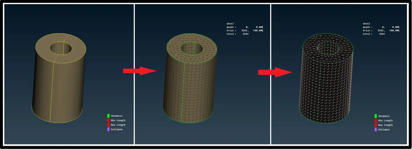
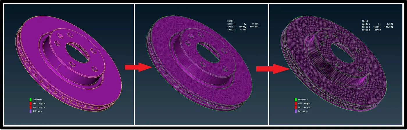
brake disk:-
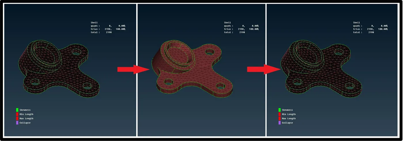
ball joint pin:-
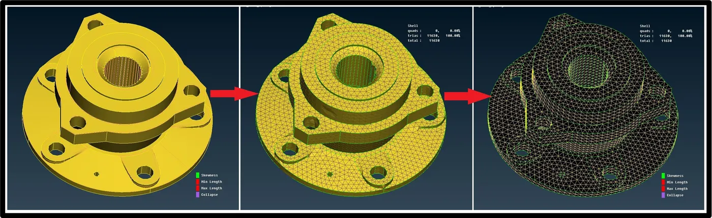
wheel Hub:-
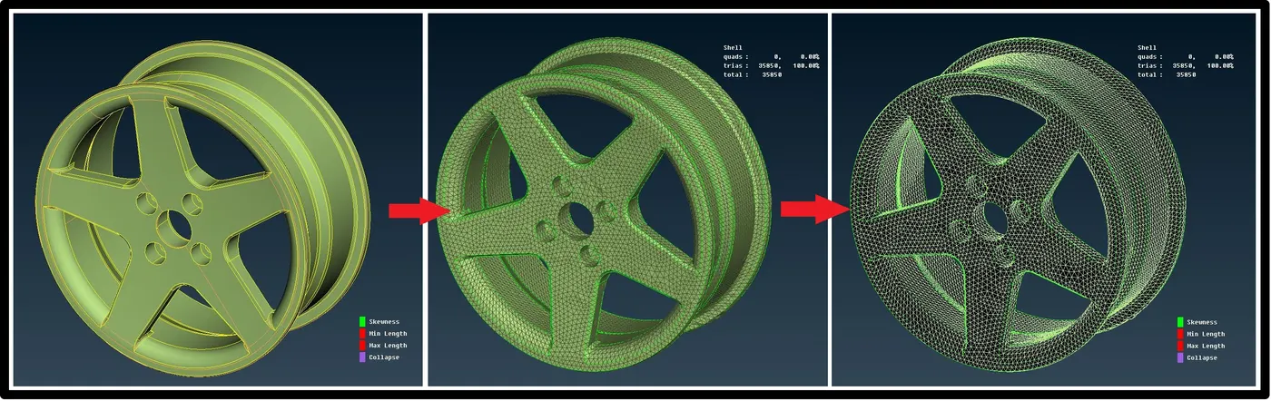
Quality criteria for Tyre and rim:-
Tyre:-
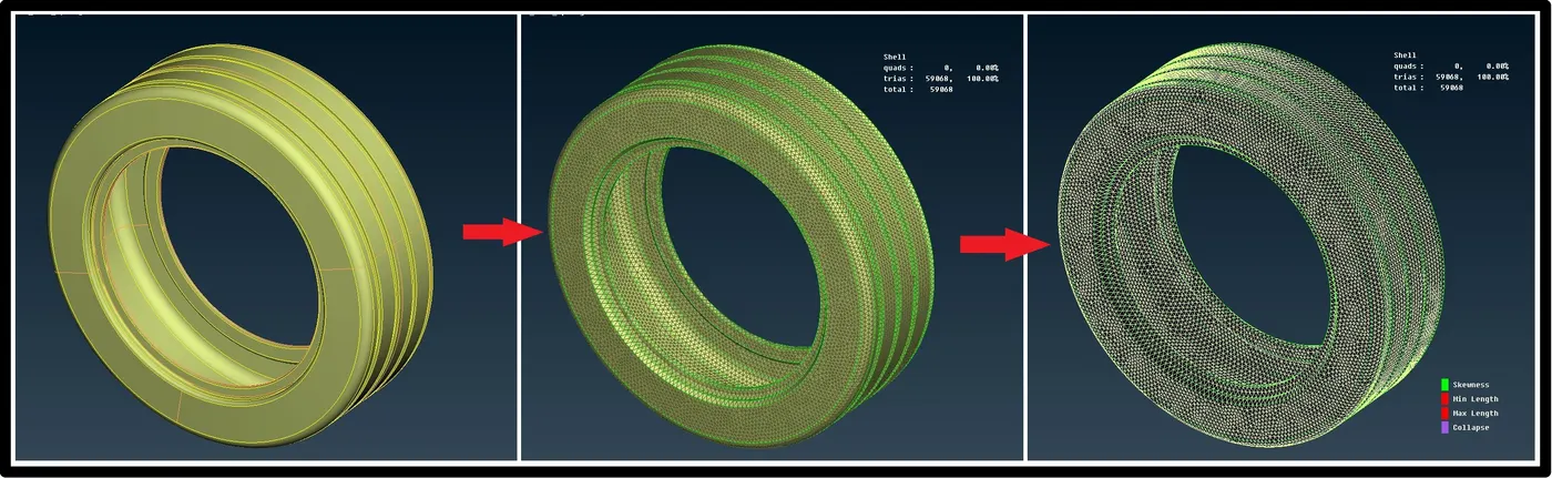
Rim:-
1 D Element:-
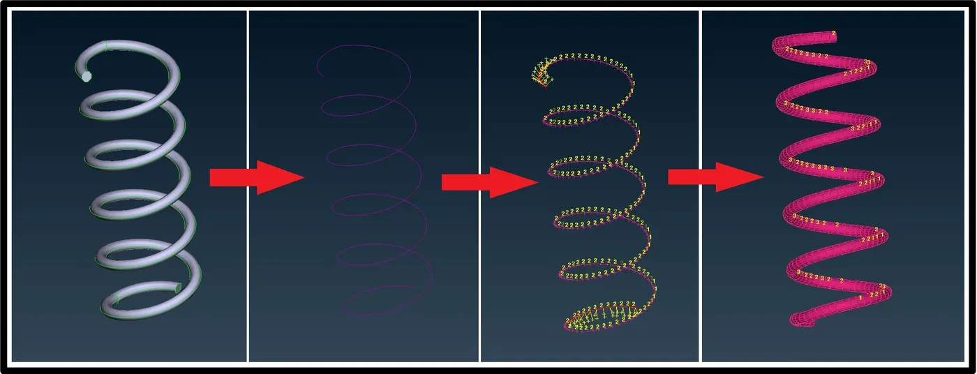
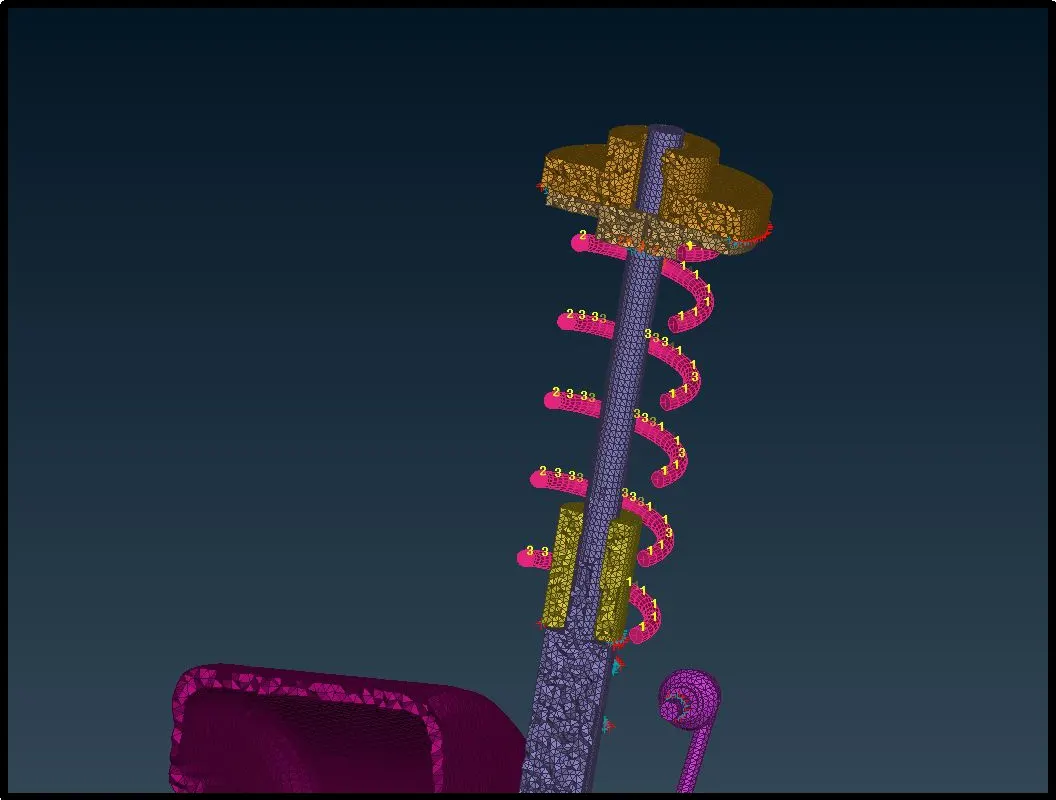
Part with the same cross section all over its length can be considered and converted into 1D elements. In suspension system, there is one helical compression spring with uniform cross-section can be considered as 1D element.
To convert it we first have to create centre curve. Then using CBAR button mention the element size and create PBAR property in which mention Outer radius and thickness if part is hollow cylinder. We can see solid view by turning on line Elements Cross-section panel in Quality window in Presentation Parameters panel.
compression spring:-
Connections:-
Next connection we are going to use RB2 connection.
RBE2 (MANY NODES):-
Defines a rigid body element of form 2 (RBE2) between selected grid points, 3D-points etc. This element is a rigid body with independent degrees of freedom specified at a single grid point and with dependent degrees of freedom at an arbitrary number of grid points.
RBE2 (TWO NODES):-
This function defines a rigid body element of form 2 (RBE2) between two selected grid points, 3D-points etc. This element is a rigid body with independent degrees of freedom specified at one grid point, and with dependent degrees of freedom at the other grid point. The node with independent degrees of freedom is the one that is selected first.
On following are, shaded in yellow, we are going to deploy above both connection. First, on each hole we are going to deploy separate RB2 many nodes elements which master node we well use to connect the RB2 connection.
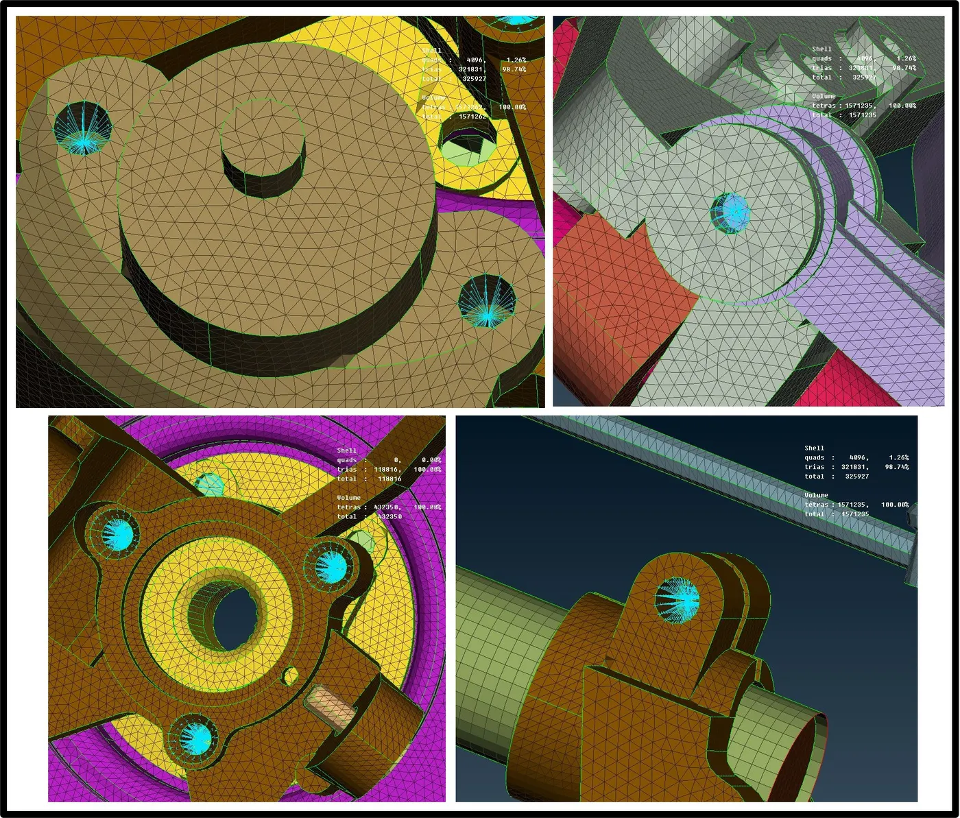
Other areas, where two part are attached each other we consider it as rigid connection and will going to deploy RBE2 many node connections.
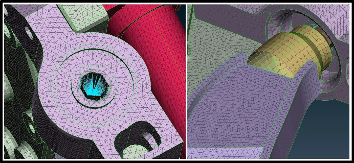
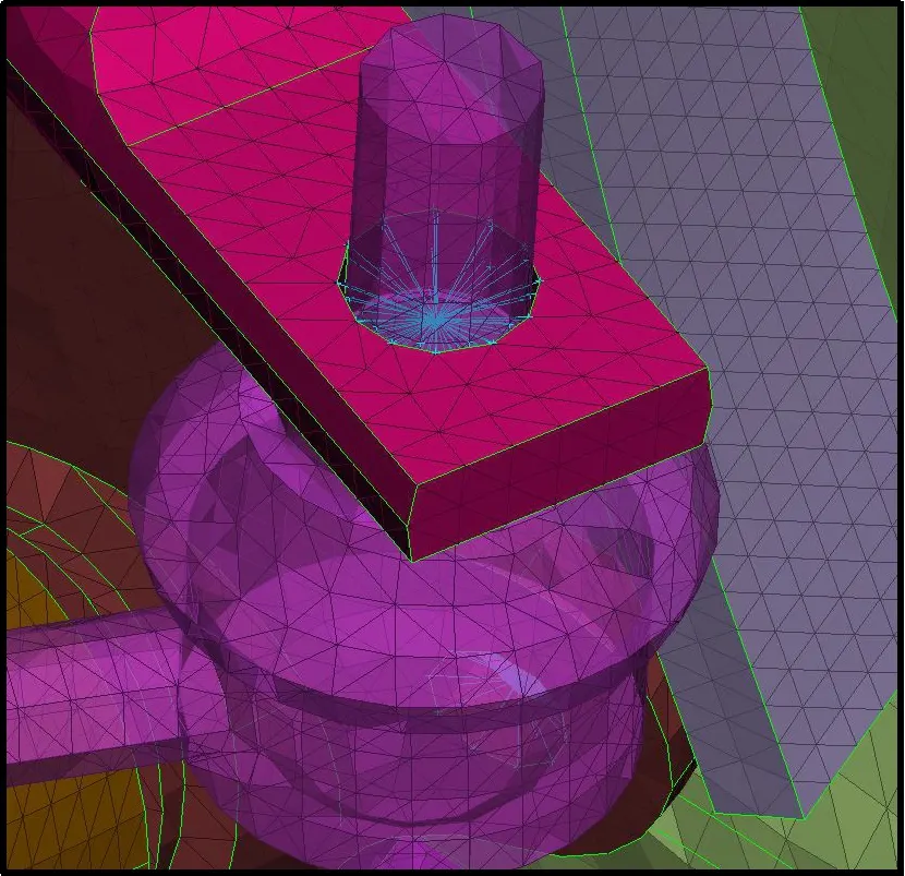
For compression spring connection we are going to deploy RBE2 two point connection as per exhibited below.
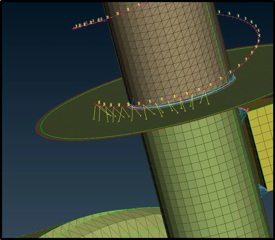
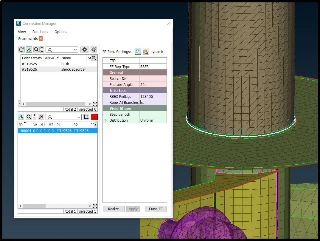
For below part section, we will first create seam line to deploy RBE3 connection as per depicted in following pictures.
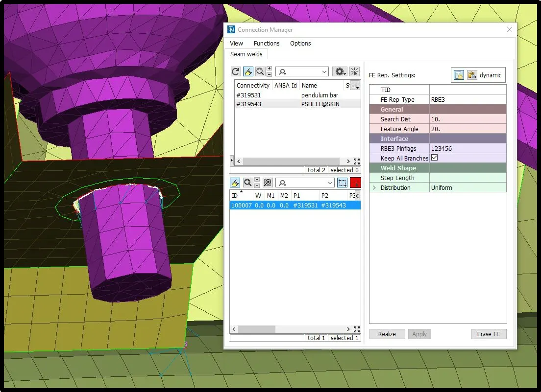
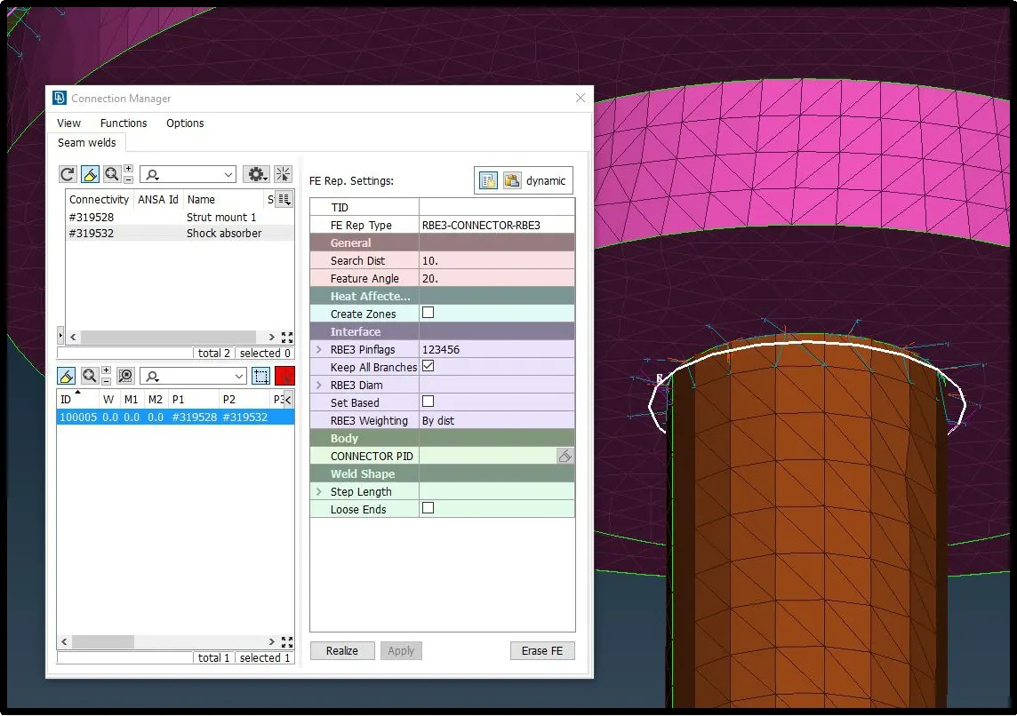
Overlap welding:-
On the overlap surface to deploy proper weld connection we can use overlap wending. To generate this type of connection first we have to create curve using FE to curve button and convert it to seam line. Use this seam line to connect two part which is overlapped to each other and which mean to be connected by welding.
Following section can be use as best representation for the overlap welding.
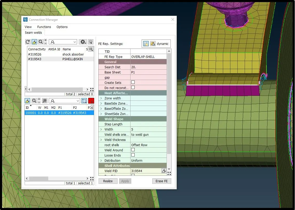
Shell as solid
And last task to visualize thickness of the generated element. For thickness visualization we can convert shell mesh to solid with the help of thickness we had assign in property id of each surface. Go to Quality > Presentation parameter > Draw shell as solid and click apply.
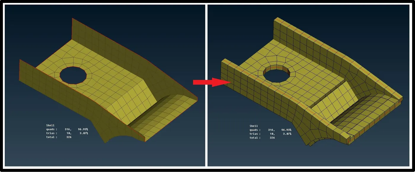
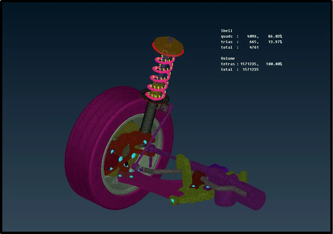
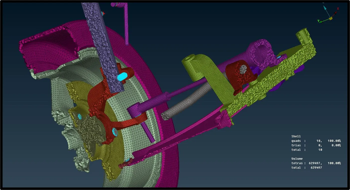
Complete geometry and FE representation:-
Conclusion
Utilization of overall lectures knowledge to extract mid surface and to deploy mesh on given rear suspension model.
Implementation of connection as per taught in previous lectures of connections.