Project 2 - 2D meshing on the instrumental Panel
Aim :
To take a proper midmesh for instrumentation panel
Geometry checks and cleanup needs to be done for proper mesh flow
Using casting method mid mesh is extracted
Proper mesh flow and quality criteria needs to be obtained
Component : Instrumentation panel
Quality criteria :
S.No Quality Criteria Value
1 Target/Average length 4
2 Minimum Length 2
3 Maximum Length 6
4 Aspect 3
5 Warpage 15
6 Skewness 45
7 Jacobian 0.7
8 Minimum Quad Angle 45
9 Maximum Quad Angle 135
10 Minimum Tria Angle 30
11 Maximum Tria Angle 120
10 Tria Percentage 15
Procedure :
Steps 1
Import the Geometry check for single cons if present use topo as required
Perimeter length and macros given values for better resolution
check for geometry if there are errors needs to be fixed by auto fix or manually
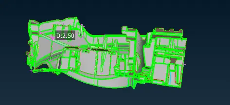
Then using the casting method mid mesh was taken
Using midsurface casting the mesh was generated for the component
Steps 2
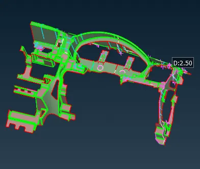
Thickness was given 0.4 the component was split in two half
Both of them mesh was generated and then alligned as normal
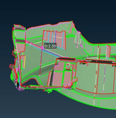
Then using the allign manager the surface which was not generated properly are reconstructed
The surface is selected which are not proper used new or edit options or manually also corrected
To reselect both the sides for better mid mesh and this done on doghouse for better surface
Steps 3 :
To reselect both the sides for better mid mesh and this done on doghouse for better surface
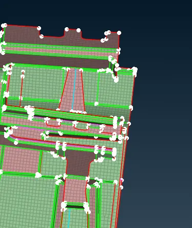
Areas option plane option is mostly used for straight surface on allign manger for straight surface
Areas middle is used for curve surfaces and straight surfaces
Perimeter is used to get the edges proper holes as per the geometry to adjust
Some places the mesh was distorted it was corrected by deleting and using shell or middle
Some of the edges were given edit faces under perimeter for definition
Steps 4 :
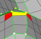
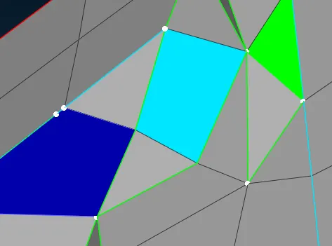
By measuring the thickness some doghouse offset given for half of the value
These are done for empty region each region middle plane offset are represented by different colors
Some of the regions curves are used to make curve and shell fill used to make the mesh
Using shell project points curves are projected and worked for better feature capturing
As the regions are properly defined as per geometry these process are repeated
Steps 5 :
Then meshing is done as per quality criteria values for proper mesh flow
Some regions are reconstruct and most of the issues are fixed
There are some regions where the quality is not captured as it was automated process minimum length failure
Most of the regions are fixed by supressing the unwanted lines
This is done to obtain the quality criteria
Learning Outcomes :
Using the casting process midmesh generated
Align manager is used in the process for saving time
Different options under Align manager was used
Time saved by using the process compared to manual method
Quality criteria is obtained in the mesh as provided
Conclusion :
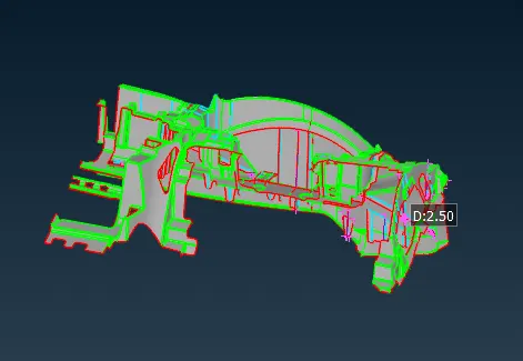
Instrumentation panel midmesh is extracted and mesh obtained as per quality parameters The complete file is attached for reference
Link for the model : https://drive.google.com/file/d/1T17sl3aSSj64i_9X078zjR5IGnb1lQvY/view?usp=sharing