Project 2 - 2D meshing on the instrumental Panel
Aim
To check for the geometrical errors and mesh with the given element Quality criteria and after meshing the component the thickness has to be assigned, for the given component.
Procedure
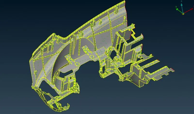
Imported the CAD geometry using the open option on ANSA. As ANSA supports the .igs, .stp, .stl files hence the challenge .stp file is successfully opened.
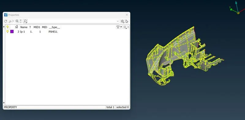
Checked the property ids, and defined the material for the seat cover by going to the material tab and ticking the define tickbox.
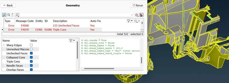
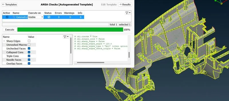
Geometry checkup for the whole component is performed using checks > geometry > execute and errors are generated. Then selected all the errors and performed auto fix on them and fixed them and lastly again executed the checks geometry for any further errors. Hence in this way geometry cleanup is done.
Now as done with the geometry cleaning measurements were taken for the sheet metal component for its uniform thickness for all the property ids and viewed them all by turning on the measurement tab in the database panel. (Used F12 to turn on database panel)
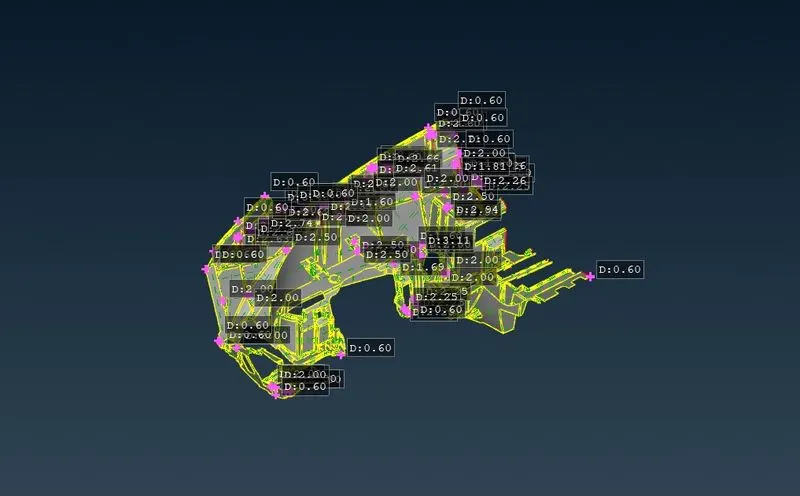
Now as the measurements are done in the previous to previous step. But here the thickness is varying in almost every area, Offset faces method cannot be used for the whole component only. In some places Faces>Middle is also used. Now for the curves features, crossribs, circular features, normal midurfacing will give poor results hence Curve>Middle option from the TOPO deck to map out the curves in the middle of the feature cons and then by using those curves we can generate surfaces by projecting them to the adjacent walls. FACES>EXTEND option is used to extend the ribs and also to extend the surfaces whrerever required.
For the doghouses and other circular features used Curve>cons2curve and Curve>create to generate curves on the faces of actual geometry and then generated new surface using fitted and coons using the curves and the projected lines generated from the midsurface parts which were first generated by using Faces>Middle. After that wherever required used Faces>Intersect to intersect two faces. Also in some places at first generated the midsurface and then projected the midsurface permeter CON lines to the faces of the actual geometry and then used fitted option to generate extra surface upto the top layer of the faces of actual geometry so that proper midsurface is generated.
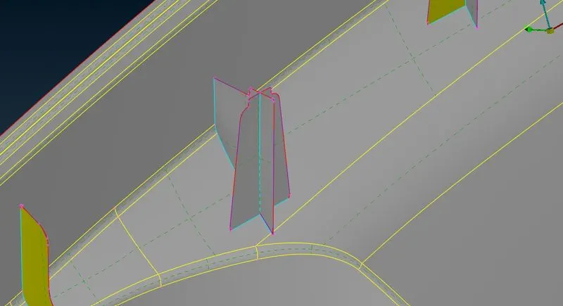
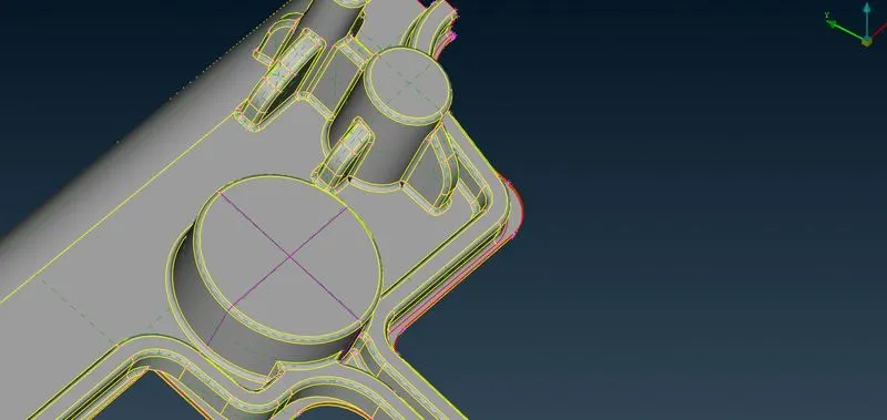
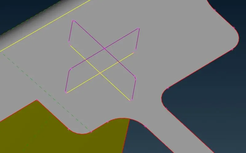
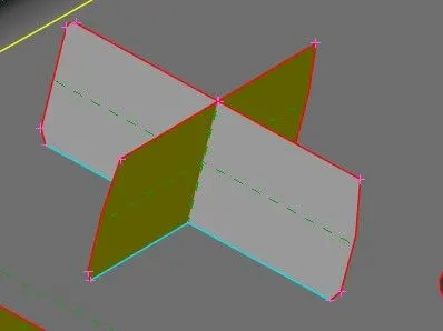
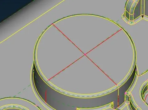
Curves used for complicated features:
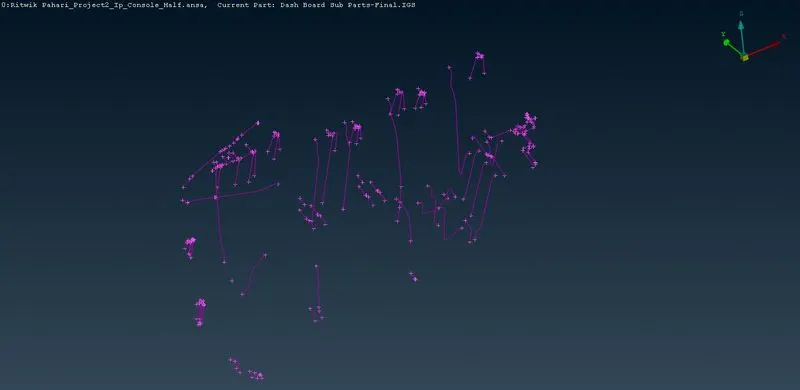
The SetPID under the Faces tab had to be used to assign the new midsurface as a new property and further assigned thickness to the midsurface. Renamed the new property ids and under T thickness is also visible.
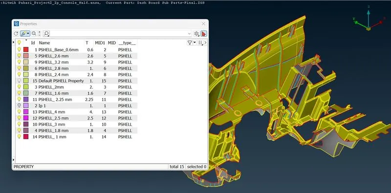
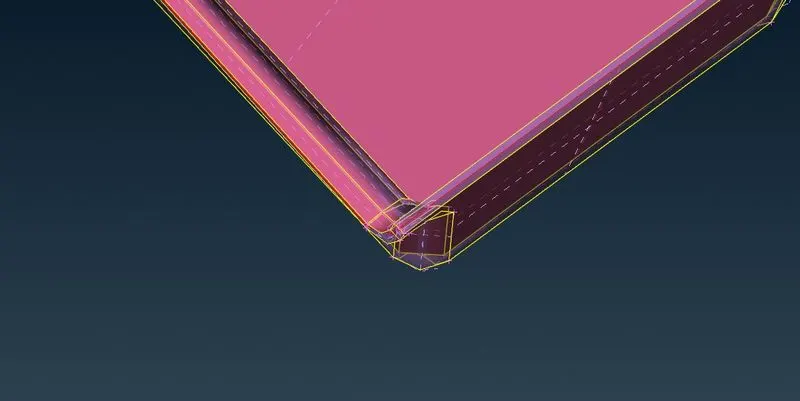
Viewed the original component and the midsurface when Transparency was on and viewed in the PID mode.
Now quality criteria is given in the question only which is as under:
|
S.No |
Quality Criteria |
Value |
|
1 |
Target/Average length |
4 |
|
2 |
Minimum Length |
2 |
|
3 |
Maximum Length |
6 |
|
4 |
Aspect |
3 |
|
5 |
Warpage |
15 |
|
6 |
Skewness |
45 |
|
7 |
Jacobian |
0.7 |
|
8 |
Minimum Quad Angle |
45 |
|
9 |
Maximum Quad Angle |
135 |
|
10 |
Minimum Tria Angle |
30 |
|
11 |
Maximum Tria Angle |
120 |
|
10 |
Tria Percentage |
15 |
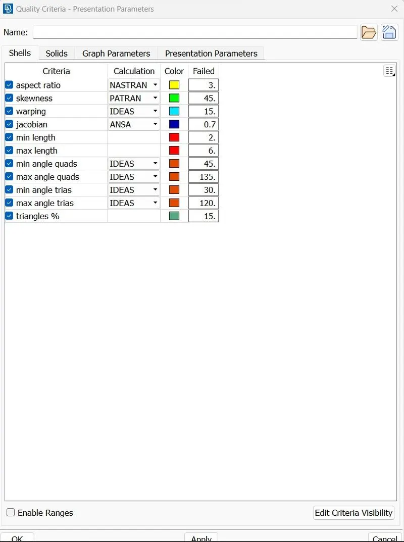
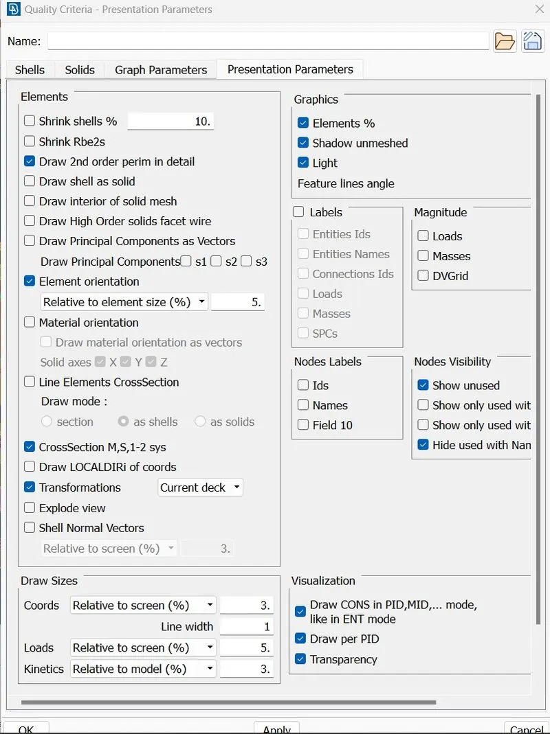
Now quality criteria is provided for quality checks so that the component is devoid of quality issues so that boundary conditions and loads can be applied further. Using the F11 key opened the quality criteria table and ticked the required quality parameters and provided the above mentioned values, hid the inactive parameters and clicked on apply. Then went to the presentation parameters and ticked the Elements% and under detail & demand effect slides the cursor and selected all details. Then pressed apply an ok to make those changes.
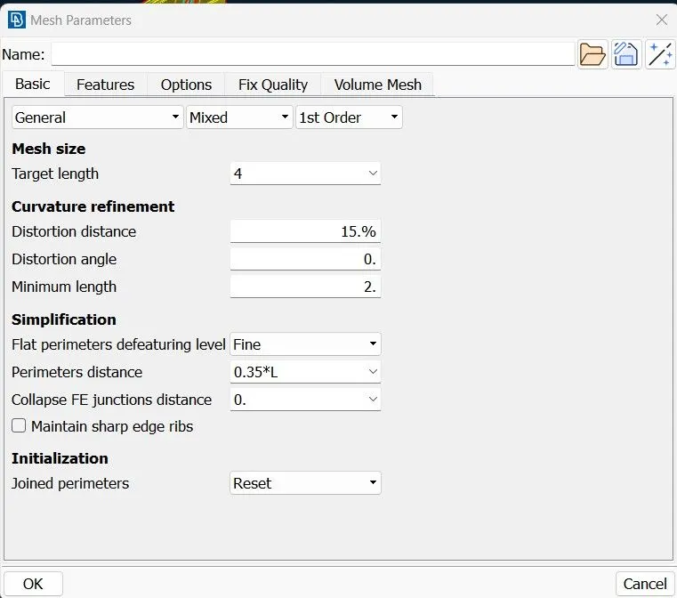
Then provided the mesh parameters such as Target length and Min length.
As all the quality parameters are given, we can go for meshing so switching to MESH deck. All the functions from now on are used from the MESH deck. All the elemental perimeter length should be equal to or nearby the Target Length hence used the Length option to redesignate the element to element distance.(MESH Deck>Perimeter>Length>Selected the whole component>Middle Click>Provided the target length>ok).
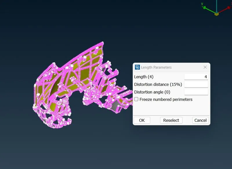
After the operation, manually checked the node distance whether the change has been applied or not. Also checked for the number of edges for the holes and found odd then changed edge number using the Number option to give the nearer even no(MESH Deck>Perimeter>Number>Selected the whole component>Middle Click>Provided the required no of edges>ok). Also NUM+/- can be used to increase or reduce the no of edges as it is a hybrid button(MESH Deck>Perimeter>NUM+/->Right click/Left click on the edges>ok). Now before going to mesh the components are defeatured by removing unnecessary surfaces, edges, otherwise bad mesh will be generated. Here the Cut option is used to join and create new surfaces as it can perform both the operations with left and right mouse click respectively(MESH Deck>Macros>Cut>Left click/Right click).
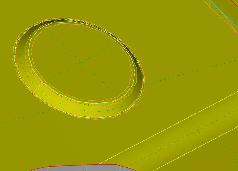
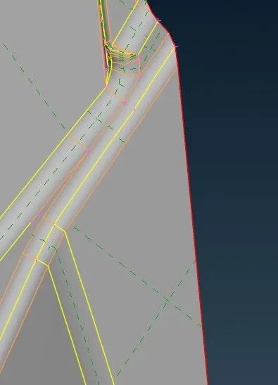
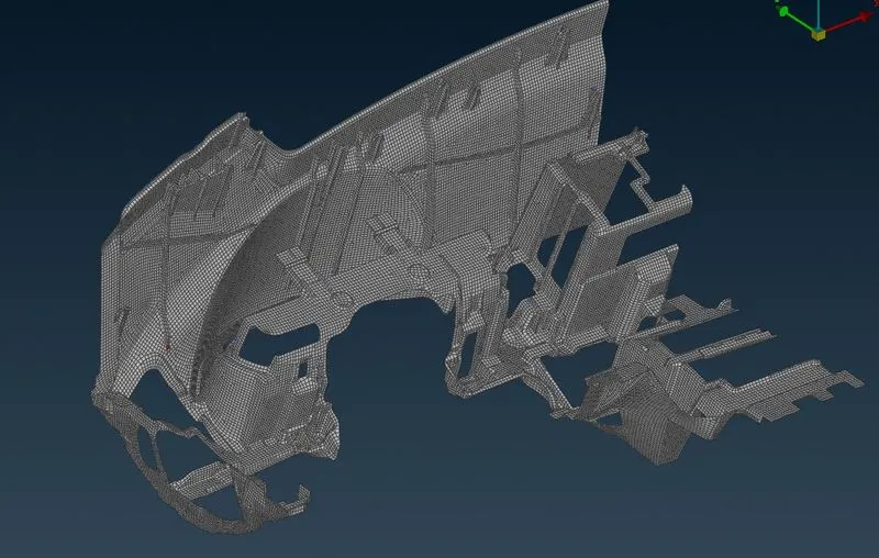
Now meshed the part using the BEST (MESH Deck>Mesh generation>Best>Select>Select the parts to Mesh>Middle Click)Mesh, as it gives better mesh results among all the other algorithms. Then turned on the hidden mode to see the quality criteria and the elements which are failing to meet quality. Then Reconstruct(MESH Deck>Shell Mesh>Select the elements>Middle Click x3), Smooth(MESH Deck>Shell Mesh>Select the elements>Middle Click x3) to reconstruct and smoothen the mesh flow respectively and also used these to reduce quality issues. The trias near the perimeter and opposite trias are removed using Split(MESH Deck>Elements>Select the edges/nodes>Left click/Right click>Middle Click). Also used Grids>Paste to reduce trias.
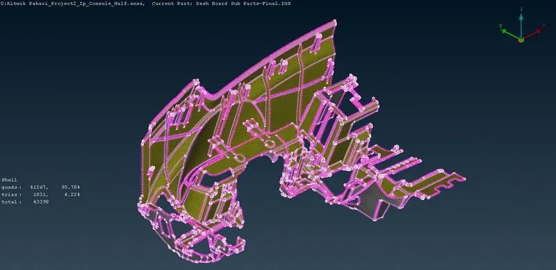
There are some off elements and it is way below 1%. To capture some features perfectly the off elements are kept.
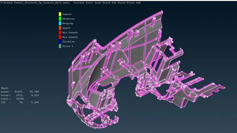
Viewed when the perimeter was off:
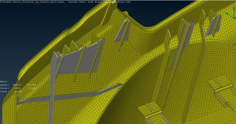
Finally drawing the shell as solid(Quality criteria>Presentation parameters>Tick draw shell as solid>apply>ok) which will enable the elements to gain the PID thickness.
Now the elements can be released by using Elements>Release(It deletes the FEM-CAD associativity) or we can export it as it is.
Learning Outcomes
At the end of this challenge I am more familiar with how to scale a model to increase its thickness, can generate mid surface for plastic and casting components, can perform defeaturing, can improve the mesh, can reduce the trias and resolve quality issues.
Conclusion
Hence the geometry cleanup, mid surface generation with assigning thickness, meshing with quality checks has been successfully done for the instrumental panel.