Project 2 - 2D meshing on the instrumental Panel
Aim:- For a given component, check the geometrical errors, extracting mid surface and perform quality checks and assign proper thickness for the component.
Procedure:
Introduction for the part: The given component Ip console, it is a plastic interior automotive component located at the head of the driver, it displays instrumentation and controls for the vehicle.
The part has various features like locator pins, ribs having a variable thickness so, the manual offset method mid surface takes more time compare to other mid surfacing methods.
In this scenario, I used casting middle mesh technique.
Steps & techniques followed
- Imported the model, checked the connection between surfaces and established connection between surfaces and performed geometrical checks.
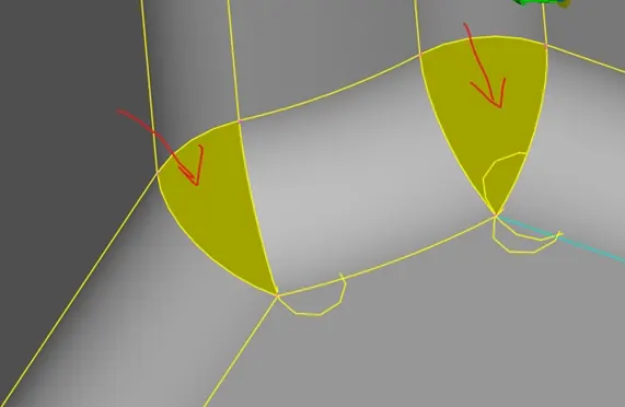
As seen in the above picture, the double cons were formed where the surface missed. This error resolved by releasing and deleting the cons then, forming a new surface in the empty region.
- After performed the checks, by using the casting technique extracted the mid surface, it is a method extracts mid surface and generates middle mesh on the surface
a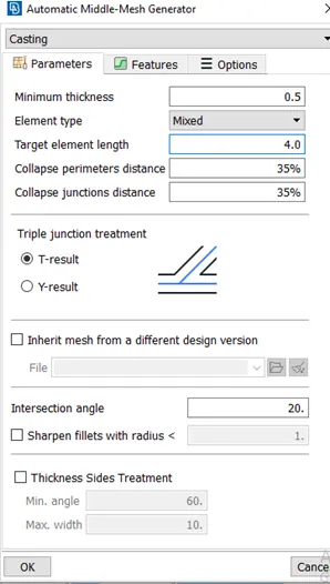
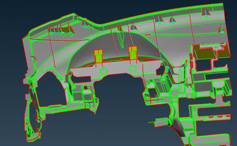
Middle mesh generated on the component
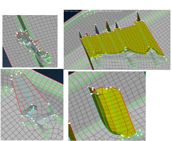
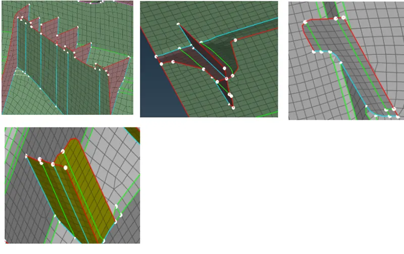
Above pics illustrates the collapsing of features on the mid surface, those extracted by casting technique so, these are fixed with the manual techniques and with the align manager.
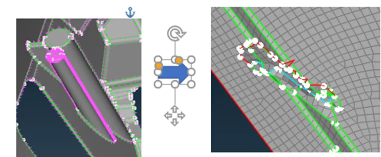
As the above feature, it is fixed manually by deleting and creating.
Use the curves, taking the middle for rib for recreating the surface with mesh using fill option.
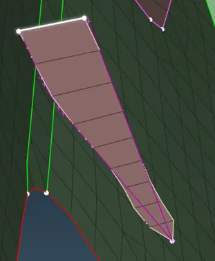
The surface has been created, then projected the cons to the surface, filled the elements.
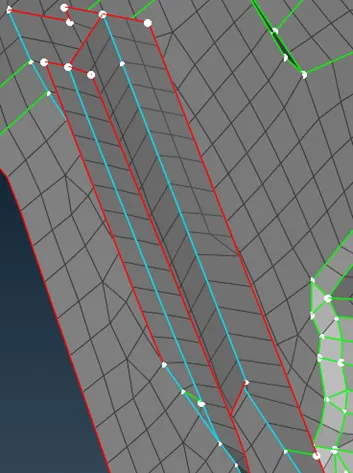
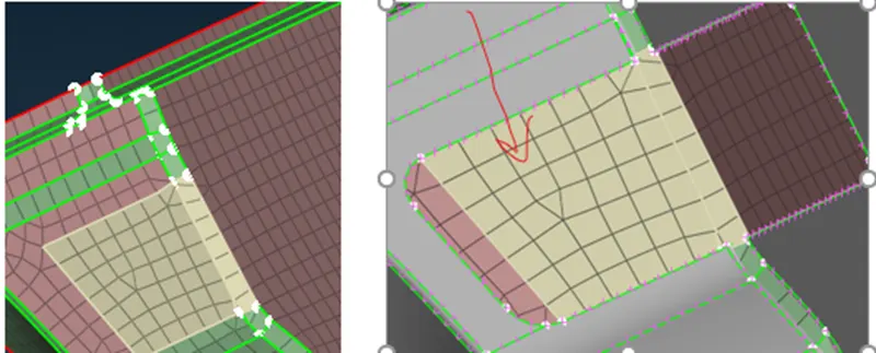
The locator’s pins are collapsed those are recreated with manual techniques and given definition with the align manager.
As observe the geometry, the empty shells are created in the hole region by default so, by using imprint technique copy the cons to the mesh surface and deleted those areas.
Then using perimeter in align manger by selecting faces as boundary, it created open single cons where the proper definition created.
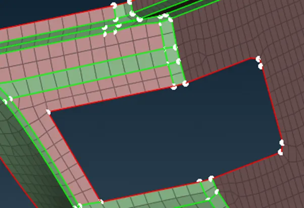
The region is created
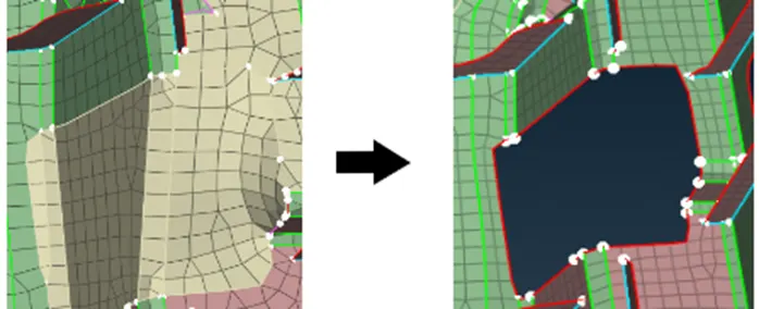
The same procedure followed for above feature.
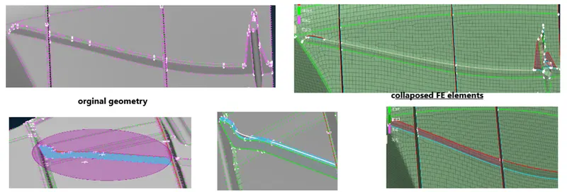
As seen the above feature, it is reconstructed by taking middle curve, recreated and fill the elements between two curves region by choosing fill option, cons method.
After reconstructed the FE surface, the definition is assigned by align manager, plane offset method and the boundary assigned by perimeters faces method.
Meshing:
For this component, we used casting method, it generated middle mesh so, need to contrate on the better mesh flow.
- To establish the better mesh flow used the manual techniques splitting the elements, collapsed the trias, reconstruction meshing methods are used.
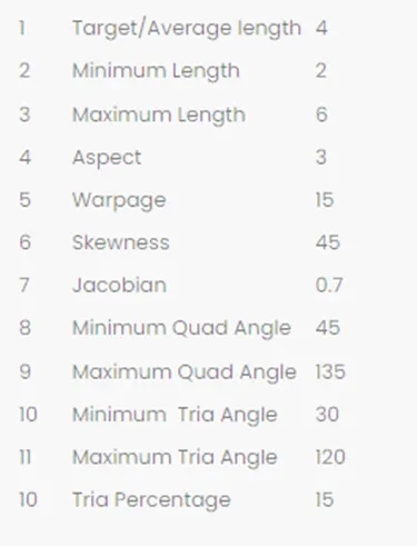
- Assigned the quality criteria and meshed as per the parameters.
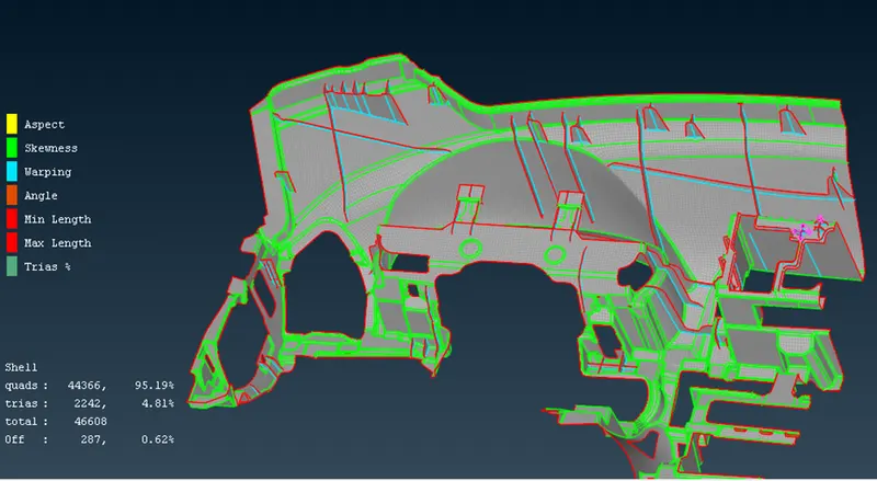
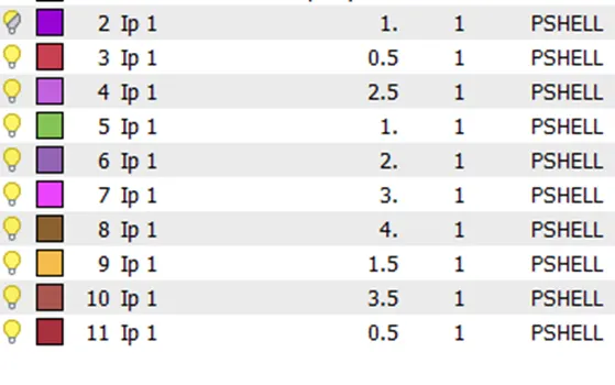
- Created the PID’S for the component and assigned the thickness using thickness and convert method.
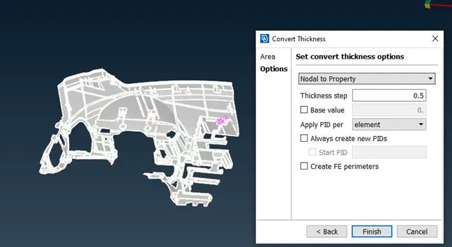
This method automatically assigns and creates new pid’s for the component. The convert method incrementally adds thickness to maximum thickness value.
And it takes nodal thickness and automatically assigned thickness based on the component to the FE macros.
Conclusion
Followed the casting technique, the ip console had been meshed and assigned the thickness to mid surface.