Project 2
Aim
To check the given industrial project for geometrical errors, mesh and connect the model.
Procedure
Step -1 Study of the model:
- The model was that of a suspension assembly.
- It had components like wish bone, strut, steering rack, tyre, rim disc, calipers etc.
- The model had regions that needed to be solid meshed and regions where midsurface had to be prepared.
- Mainly bolt connections were needed and spring had to be modeled as one dimensional C-Bar.
Step -2: Standard geometry cleanup.
- The model issues.
- Most of it was fixed automatically using the FIX option from the geometry checks manager.
- The rest of triple cons were removed manually.
- Then it had many damaged surfaces it was deleted and new surfaces was created.
- Then the model was ready for meshing.
Step-3: Mid-surface preparation.
- Here the parts with uniform thickness less than 5 mm were mid-surfaced.
- So strut was the only component that had parts with uniform thickness.
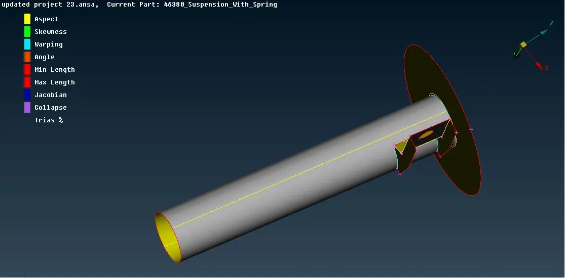
- The cover of the strut coloum was mid-surfaced using offset option.
Step-4: Creating volumes for tetra meshing.
- Each component that had no uniform cross-section or thickness was defined for solid meshing.
- The parts were isolated using “! Not” option.
- Then from volume deck define tab was selected and volumes were defined manually.
- Then from list tab the volume can be chosen.
- Each part was separately checked for errors which prohibited solid meshing.
- Mainly penetration errors were found. This was ue to the bad geometry.
- Then troublesome areas were cleaned by deleting the surfaces and creating new ones.
- This way each solid part was ready for meshing.
Step-5: To type in the quality criteria.
- The quality criteria differed for parts.
- For tyre and rim tria elements length were given
- Max length -10
- Min length-5
- Target length-6.5
- For other parts;
- Max length -6
- Min length-2
- Target length-4
For mid-surfacing
- Max length -6
- Min length-2
- Target length-4
- This way mesh parameters were defined as needed.
Step-6: Meshing and checking.
Midsurface meshing:
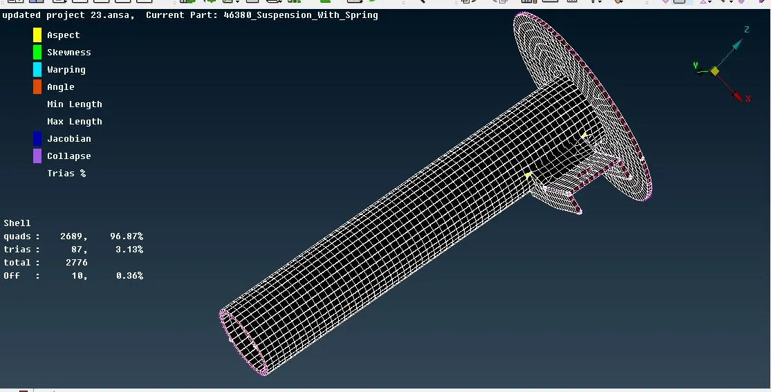
- Then each part was selected and meshed according to the needed quality individually.
- The mesh was checked and reconstructed to ensure a good mesh flow.
- The number of trias were reduced using split, swap and paste options.
Solid meshing:
- The meshing is unstructured tetra meshing. That is elements with four edges were used to mesh the component.
- Capturing of solid features is of prime importance.
- The meshing is done initially on the surface using ortho tria and tria mesh. Ortho tria mesh was used in curved areas whereas the tria mesh was used in flat regions.
- If the mesh creates height differences on the surface it was reconstructed. The process of meshing was completed individually for each volume.
- It was ensured that a good mesh flow was achieved for each surface.
Step-7: Connecting the different components.
Bolt RBE2 connection:
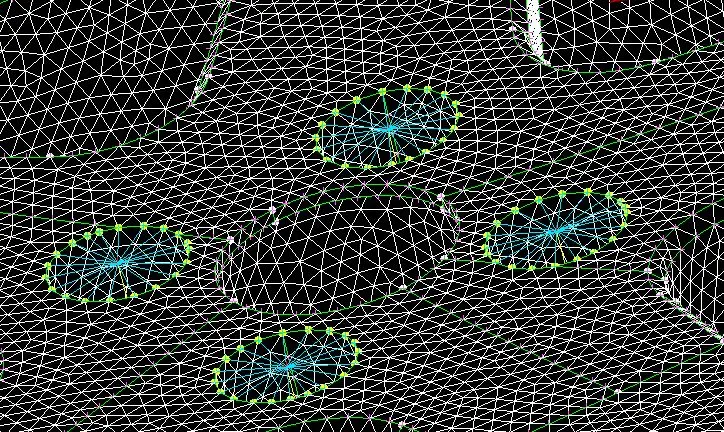
This connection was done in places where multiple parts were joined together by a single bolt. The bolt connection is realized as follows.
- The many node RBE2 connection were chosen.
- The nodes forming the hole were selected as the slave nodes.
- They in turn create a master node.
- Similarly the other hole nodes were selected and master node was realized.
- Then two node RBE2 was selected and the two master nodes were chosen.
- This way a bolt connection was realized.
One dimensional C-Bar connection.
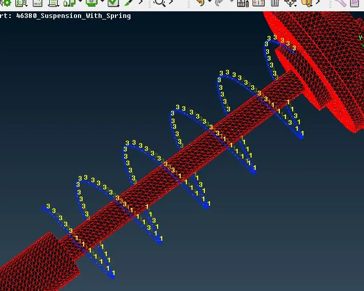
This connection was used to show the spring in the model.
- A middle curve was created for the spring geometry using middle option in curve tab.
- Then the C_BAR option was chosen from connection tab.
- The curve was chosen and the length was given,
- It was realized as line element.
Later area of cross-section was given by editing the parameters and giving radiou
.
Step-8: Giving volume to the shell mesh
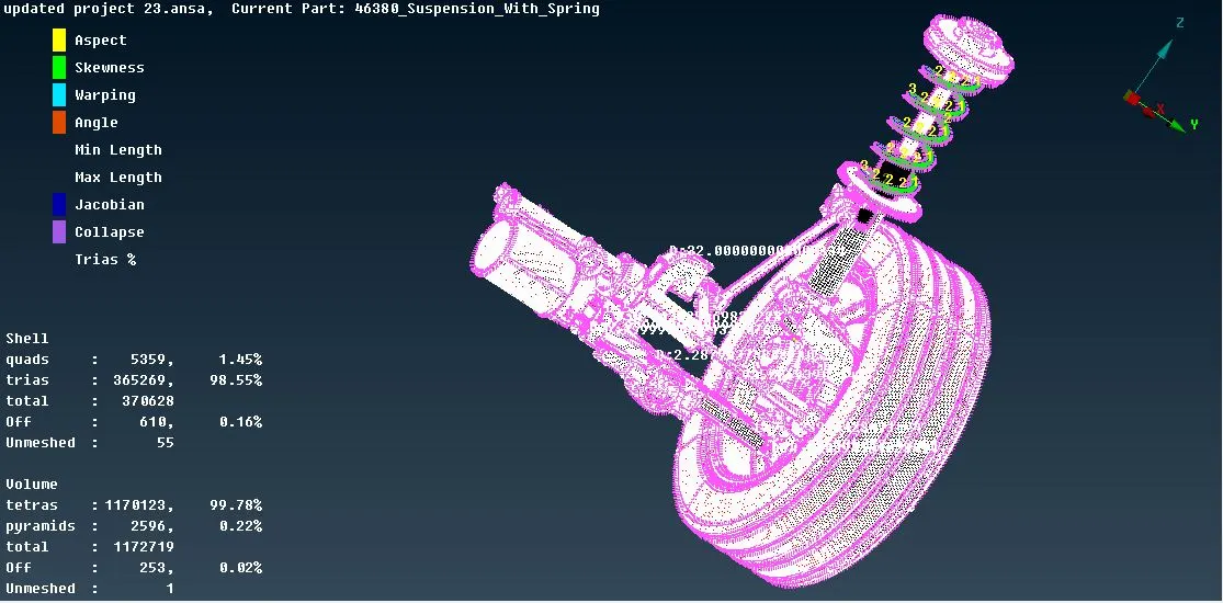
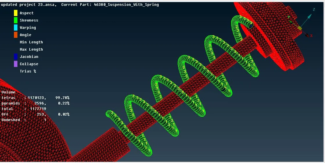
- Each different volume is selected and initially the status unmeshed. Then the unmeshed volumes are meshed using any of the available algorithms. Here ‘Tetra rapid’ was used.
- Now the shell mesh on the surface is literally grown into the cad’s inside volume. The growth pattern is unstructured and hence the name.
Step-9: Giving thickness to shells
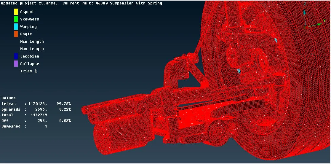
- The mid-surface with connection were given thickness by going to presentation parameters and enabling drawing shell as solid option
Conlusion and learning outcome.
This project wa an culmination of everythng ive learnt through the course. midsurfacing, solid meshing connection all were employed i this project. it was a challenge as the geometry was poor. gave an insight into how industrial scanned models are used.
https://drive.google.com/file/d/1QJG2MnGlq8SHABc1oCqJJal7JSvcw_yF/view?usp=sharing