Project 2
MOLD DESIGN FOR CPU FAN BEZEL
1 OBJECTIVE
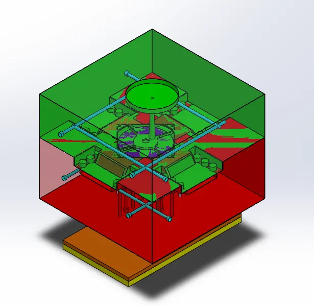
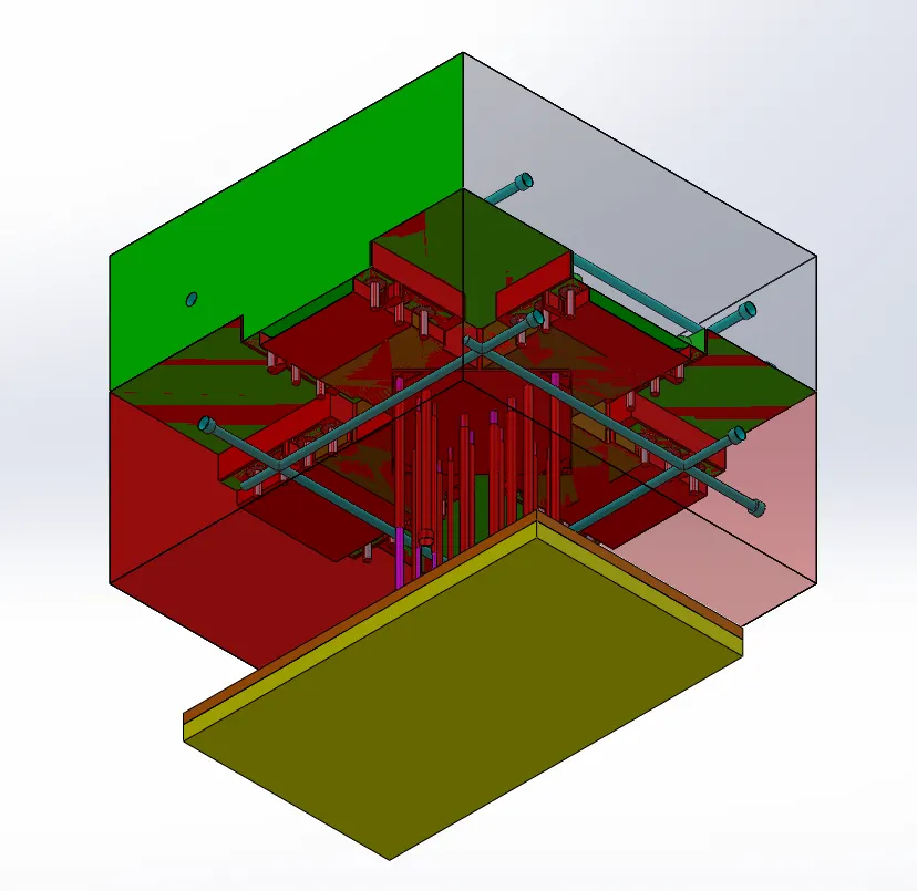
The objective of the present project is to model a mold consists of a cavity block, core block along with sliders, inserts, ejector pins, ejector plates, sprue gate for the CPU fan bezel.
2 PROCEDURE
This section consists of steps followed for creating core and cavity blocks in SOLIDWORKS.
2.1 TOOLING DIRECTION
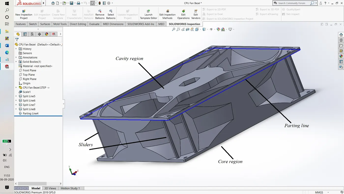
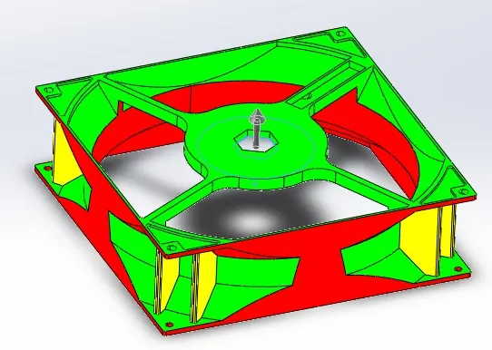
- The first and foremost step is deeply to investigate the model given by the product development team. Check the need for inserts, sliders, and parting line. Set the parting line in such a way that to accommodate minimum sliders for the model. Once the check is complete and the tooling direction is fixed, do the draft analysis using the DRAFT ANALYSIS command. The present model seems to be fair, covering all the parts in red and green color, but there exists a yellow color region. We can communicate this to the product development team. However, those regions are to be accommodated to sliders.
- The material selected for the model is ABS, which has a shrinkage percentage of 0.6%, so the scale of 1 + `( 0.6)/100`= 1.006 mm is given to the model using SCALE command.
- Now select the parting line using the PARTING LINE command. For the present model, the parting line selected by the parting line wizard is correct and proceeded with that only.
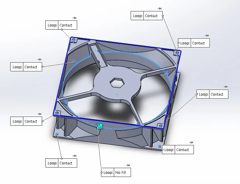
- As holes are present in the model, click the SHUT-OFF SURFACES command to close the holes that are forming near the cavity and core regions. For the present model, bottom holes cannot be knitted, but while creating the mold block, an extrude can be given for the hole region to be formed.
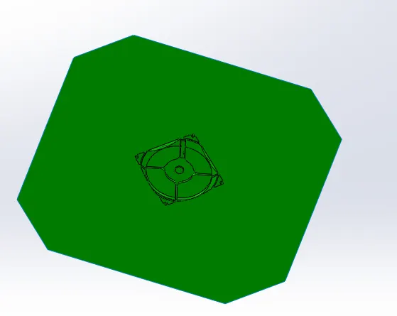
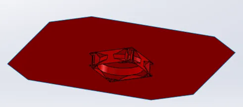
- Create the parting surface along the parting line using RULED SURFACES command and sweep option with a distance of 250 mm (not standard any value can be taken). Now using the LOAFTED SURFACES command, create surface along the edges of the model. Use the KNIT-SURFACE command to merge all the parting surfaces.
- Create a copy of the parting surface using the MOVE/COPY BODIES command.
- Now hide one of the parting surface and core region. Using the KNIT-SURFACE command, join the core and parting surface. Similarly, do the same to create the cavity surface.
2.2 CORE AND CAVITY BLOCKS
- Now save the part file in a new assembly file. Create two new part files and save them in the same assembly file. Rename the two-part files as core and cavity steel blocks.
- Check the origin of the assembly. Float the model and mate the corresponding planes according to the gate location as the model has deep cuts on all the four corners. The part is rotated to 45º using the ROTATE COMPONENT command. The gate location is not given in the model, so the center portion is selected as the material inlet location. Fix the model.
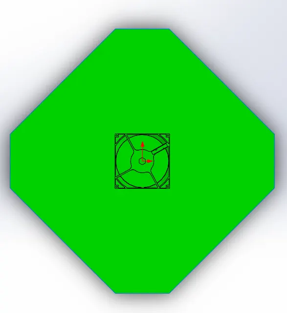
- Edit the core steel block. Take the top plane and sketch a rectangle with a length as 360 mm and width according to the ejector plate width (220 mm standards will be given in the industry catalog) + spacer block (2×45 = 90 mm) + slider (50 mm) = 360 mm.
- Extrude the rectangle using the EXTRUDE command in both directions with 200 mm (try to keep the thickness of the mold as low as possible).
- Now using the OFFSET SURFACE command, offset the core surface with 0 mm.
- Cut the extruded surface using the CUT WITH SURFACES command. The core block is created. Assign a red color to the block.
- As no curved or 3D profile is present at the parting surface, no need to create an inner core block for the present model.
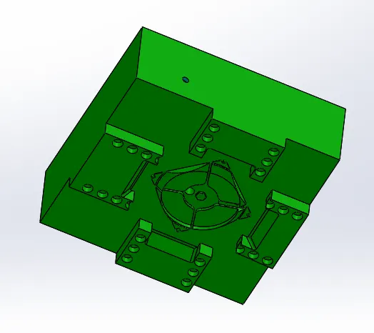
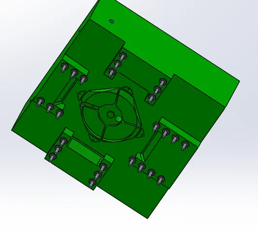
- Edit the cavity steel. Select the top plane and use the same rectangle sketch of the core block. Follow the same steps to create the cavity block. Assign a green color for the cavity block.
2.3 SLIDERS
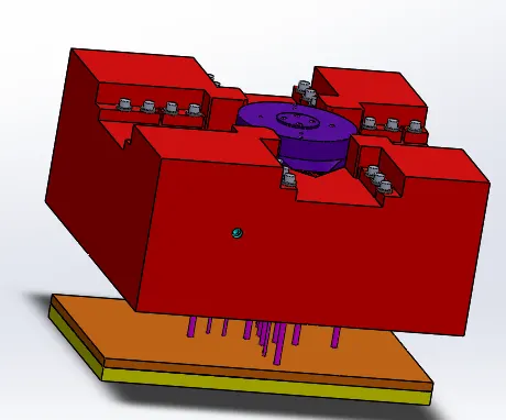
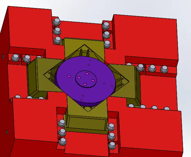
- For the present model, an estimation of four sliders is required in all four corners.
- Select the top face of the core block. Sketch the slider such that not thin steel should present either in the slider or the region of the slider in the core block.
- Create a reference plane up to which the slider should present.
- Use the SPLIT command with a plane and sketch it in the tooling section. Click on cut bodies. Select the slider region.
- On the side face of the slider, CUT EXTRUDE the extra region. For the slider to move while removing the cavity block, sketch the wedge shape on the side of the slider with 30º and heigh as 2/3rd from the top surface.
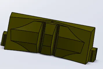
- Sketch the bottom portion of the slider to create the slider pathway, sketch a rectangle with 5 mm and extrude to the wedge surface.
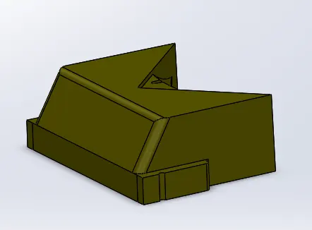
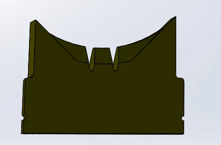
- Save the slider in the external file in the same assembly path file.
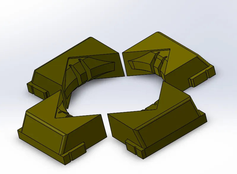
- Subtract the slider form the core region using the COMBINE command and subtract option.
- Using the MOVE FACE command clear the pathway for the slider in the core region.
- Sketch the core region where the pathway is created to accommodate washers for the slider to move.
- Create washers in separate part files and in the same region where washers are present, create holes in the core block using the HOLE WIZARD tool.
- Sketch the locking mechanism in the core region and slider path region. Make sure the move sufficient distance (extra 5 mm) for the smooth removal of the part from the mold.
- Edit the cavity region. Extrude the region where the slider part is present. Create holes for the washers and nuts.
- There is a 90º contact between the cavity and core block. So a relief of 2 mm is provided in the core block at all the contacts.
- Fillets are provided in all the required corners of sliders, core, and cavity blocks with a 3 mm radius using the FILLETS command.
- The same process is used to create all the sliders in all the other three corners.
2.4 EJECTOR PINS & PLATES
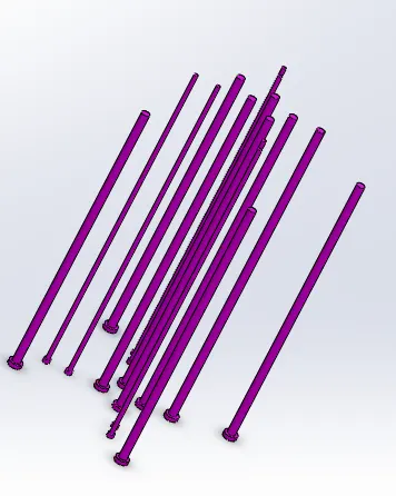
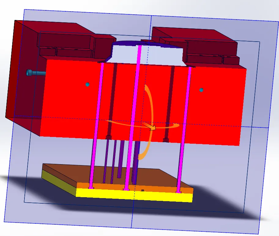
- Ejector pins are circular rod-like structures that are used to eject the part once filled from the core cavity.
- The ejector pinas are usually located near the in-depth cut features.
- Ejector pins come in standard diameter (3 mm or 6 mm), standard lengths.
- Sketch the region where ejector pins are required, and CUT EXTRUDE the region.
- Using the same sketch, EXTRUDE till the surface with standard lengths.
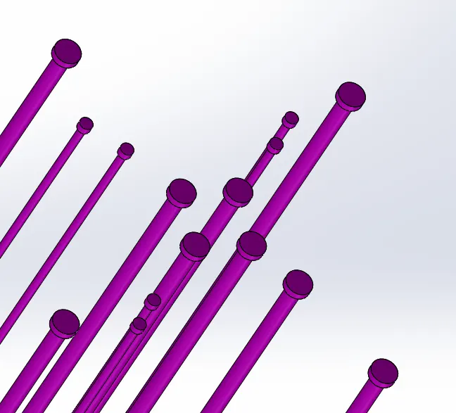
- On the pinhead, create the ejector pinhead. As the part surface is flat circular pinheads are created with standard dimensions.
- Take the pinhead as the sketch and draw the ejector plat with standard dimensions width (170mm or 150 mm), length as same as the block length, thickness 10 mm. Give the pinhead region and relief of 6.95 mm or 3.95 mm both in plate and block.
- Create an ejector backplate on the back of the ejector plate.
2.5 RUNNER AND GATE
- The material enters the mold region through the runner and gate system.
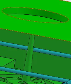
- There are different types of gate systems. The most used is the edge gate system for thin bodies. For the current model, a sprue gate system is used.
- The sprue gate system is modeled in the cavity region.
2.6 AIR VENTS
Once the mold is filling, air will be present inside the mold blocks. To remove the air from it, Air vents are created in the core region. If air vents are not created, air voids will be present in the model, and they will be defects in the model.
2.7 COOLING SYSTEM
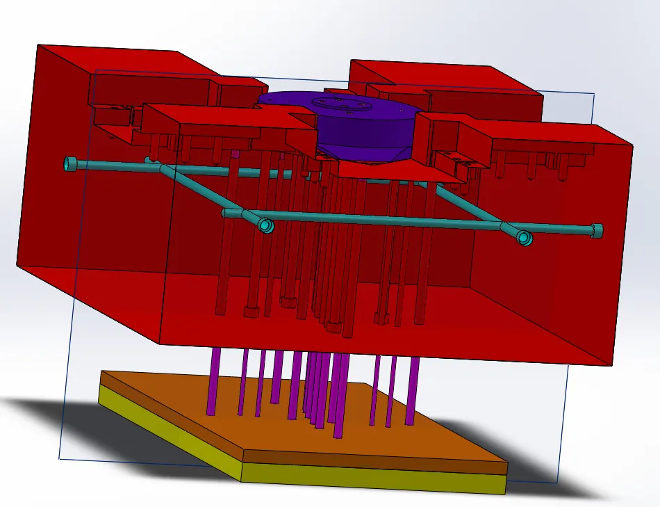
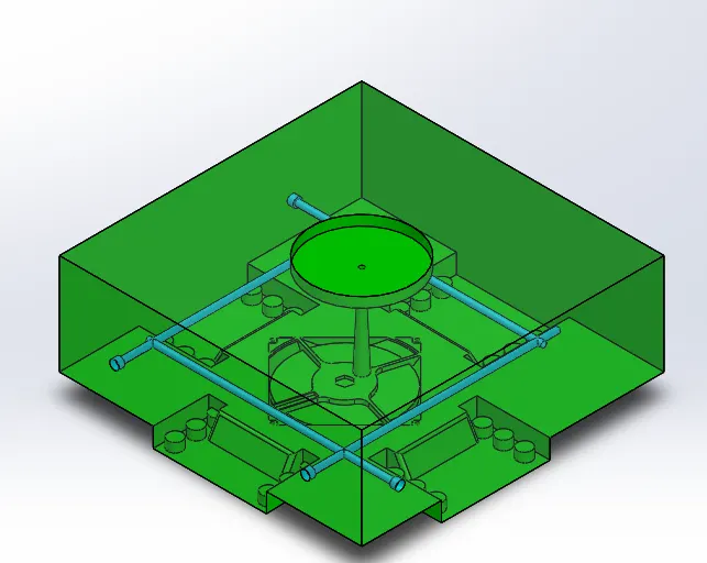
Mold cooling accounts for more than 2/3rd of the total cycle time. A proper cooling channel decreases the mold time, increases the production of components. More cooling increases the cost in the long-run, but inadequate cooling wraps are present in part. Using HOLE WIZARDS, cooling channels are created with inlets and outlets.
FULL MOLD BLOCK
3 CONCLUSION
The mold block for the CPU fan bezel is modeled and designed in SOLIDWORKS.