Solid Finite Element Meshing on Suspension system with connection for NVH (NASTRAN) Simulation
Aim: - To check for the geometrical errors and deformation in the Suspension system model. Performing a proper mesh and deploying the connections on the components of the suspension system.
Overview
In this project, the model I get was a Suspension system. As you have known the suspension system is quite a large assembly due to the numbers of components present in the assembly. I had given the half section of the system with the task of the mirror after completion of the mesh and connections as it was symmetric in construction. The idea behind this was the laser the component easier to work on them. On the other hand, in some cases, ANSA would not able to take a load of such large assemblies. [may vary with your System specs.]
The model I got was a Mac-Pherson Strut-type Suspension system. My role here is to identify the areas/parts where I should deploy 2D mesh and 3D mesh or just capture it with 1D elements. Then have to do proper connection in-between mating parts as per the requirement.
Methodology
The basic steps are as follows
1) Import model and Go for the Length option from the mesh module (Deck) to find out the actual geometry of a model.
2)perform topo on it. As the model is too distorted after importing from different software. Topo helps to merge the adjacent surfaces and clear most of the errors in the process.
3) After visualizing the model, we get the idea about which category the model will fall into. Like sheet metal/plastic/casting part. So, we can choose the meshing option accordingly.
4) For the sheet metal part which has a thickness of less than 5mm or measurable thickness, go with the Shell Mesh option.
5) For casting / plastic part if the part having a thickness of more than 5 mm solid meshing is preferred. otherwise, mid surface extraction and Shell element deploying is good practice
6)Check for geometrical errors and clean them. Segregate parts in different PIDs. Defeature areas where needed.
7) After doing Geometry clean-up and defeaturing, now we are ready to do meshing by preferring any of the above methods (Shell mesh / Solid mesh) as per the given model. (Here I am using mixed meshing as the given model have some Sheetmetal as well as casting parts)
8) Use ‘Mesh’ deck for 2D element meshing and ‘V. Mesh’ for 3d element meshing.
9) Implementing connections at required areas using NASTRAN deck. (Deck may change as per simulation types. We are doing FE meshing for NVH simulation that’s why we are preferring NASTRAN deck here)
Quality Criteria
The Quality Criteria I had followed for the Suspension system meshing are as follows,
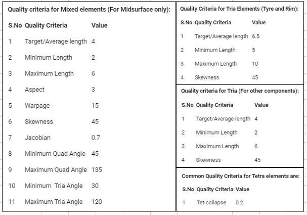
As you can see in the above image different Quality Criteria are used for establishing different types of mesh (1D/2D/3D) on various parts of the suspension system as per their construction and geometry.
INTRODUCTION
Vehicle Suspension System
The suspension system is the crucial and most important system in the vehicle. There are many types of suspension systems are available in the industry through the application of the system is the same for all.
- Maximize the friction between road and wheel during acceleration, Deceleration, and Turning.
- Provide steering stability with good handling.
- Support the vehicle weight.
- Ensure the comfort of passengers by damping vibration and absorbing shock.
When a vehicle travel on the road its experience different type of forces like Aerodynamic drag, thrust, deceleration while braking, etc. The vehicle should be compensating for all these forces and give passengers good comfort and driving experience.
Different types of terrain are available all over the world, when you drive on the normal city road you can see an uneven road surface, some sort of bumps / Speed breakers. In some villages side, you can’t able to find a good concrete road. So, your vehicle should be handling all these and provide you the best comfortable ride. Suspension systems are there to do all this stuff with good efficiency.
The vehicle without a suspension system can only be a force transmitting device. Suppose you are driving a car with no suspension in it. When such a car comes across a sudden bump or sort of speed breaker it will experience a force that has direction in vertical and its magnitude depend on the type of unevenness it came across. If the road has a larger bump the magnitude of the force is higher and without a suspension system, this large force will directly transfer to the cabinet and cause an uncomfortable ride. Also, it may cause the vehicle wheel to loos contact with the ground for some time which was not good for vehicle handling and may responsible for the accident. To avoid all this mess the engineers come with a suspension system.
Types of suspension System
- Dependent Suspension system: - The dependent suspension system has a solid axle that connects both of the wheels on either side. This Solid axle goes across the width of the frame. As per name indicates both sides of wheel suspension are dependent means if any side moves upward due to an uneven road surface or a bump it will affect the other side too. This will cause uneven wear of tires and balance issues. Also, it’s not that comfortable.
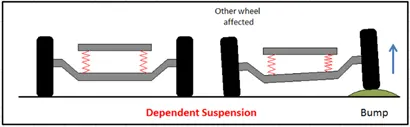
The construction is consisting of a solid axle at the base which connects wheels on either side and above that axle, the shock absorber and leaf spring arrangement are done. Some time that leaf spring replaces by a coil spring to the shock absorber.
This system is based on a leaf spring/coil spring/solid axle and can be implemented on both the front and rear axle. Most of the older truck has such suspension due to its durability and simple design. De-Dion is an example of a Dependent suspension system.
-The Independent suspension system
As the name indicates the suspension system is installed on either side of the wheel is independent of each other. No sold axle is there to connect the wheels. Due to the suspension of the front right side of the wheel independent to the front left side no sudden bump on the road can't affect both sides at the same time, Which will improve the handling of the vehicle as well as stability and control The comfort you will get from the independent suspension is more luxurious. That’s why this type is famous in the Curser and high-end cars.
There are two types in the Independent suspension system.
- Mac-Pherson Strut suspension
- Double Wishbone Suspension
These two are the most weirdly use suspension systems in the industries, let's discuss them briefly.
1) Mac- Pherson Suspension system:
It’s the same model we get for the meshing operation under this project. It has a very simple construction and design. Also, the fewer numbers of parts in the system assembly lead to low cost that’s why it's famous in most of the mass production manufacturers.
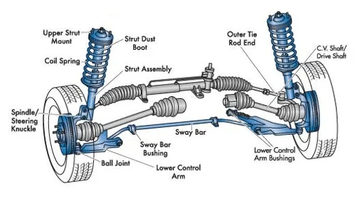
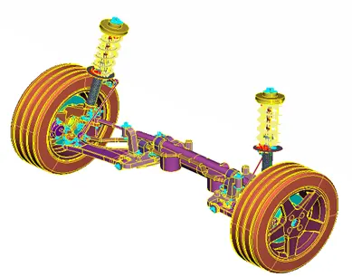
The strut plays an important role to keep the wheel in contact with the road. This system also has some cons. One f them is its vertical mounting. It takes more space in a vertical manner due to the strut and spring arrangement. So, it will shift the ground clearance slightly up which is not good for a sports/supercar. As lower the ground clearance lowers the C.G. of the car and results in good handling.
2) Double Wishbone:
It has the upper and lower arm to hold the steering knuckle. The steering knuckle is pivoted in between the ball joint of the upper and lower A-arm and the damper-spring arrangement is mounted on the lower ball joint.
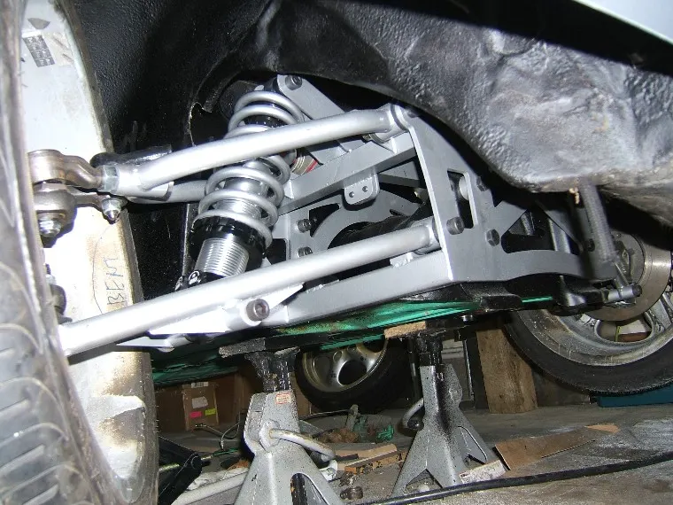
It will give you its best performance during corners as it will hold the tire to the road throughout.it provides more cushioning as compare to the mac-Pherson strut-type also not take too much space vertically that makes the system more compact and favorite to race can manufacturer. The only downside is the complexity of the design and the number of parts in the system which makes the entire system more costly than mac-pherson.
The detailed comparison you can get in the following video link:
Speedcar99
https://www.youtube.com/watch?v=MraNBaCmcok
Components in Suspension system assembly,
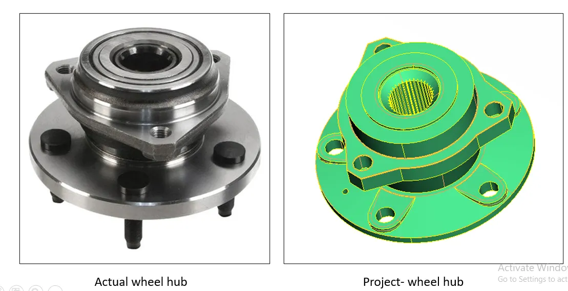
1) Wheel Hub
It’s the center part of the wheel assembly. The wheel hub is responsible for holding the Brake disc, Rim, wheel assembly together. The wheel hub also consists of a bearing that ensures the smooth and quiet movement of the wheel.
2) Steering Knuckle
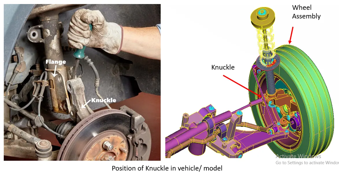
It is a very important part of suspension system assembly as its holds the wheel hub and the other important components of the suspension system like the A-arm (Control arm), ball joint shock absorber, etc. together. It also acts as a mounting unit for a brake caliper, in the case of the Macpherson type which we have here it will act as a mount and hold the shock absorber in place. In the case of the Double wishbone, the arrangement is a little bit different.
Control Arm
Control Arm also is known as A-arm or wishbone connects the Knuckle sub-assembly to the Subframe. The design of the control arm changes from manufacturer to manufacturer/company to company. But the application remains the same with a slight improvement here and there. the secondary application of the Arm is to damp the small vibration which becomes successful because of the bushing. A ball joint is mounted on one side of the control arm.
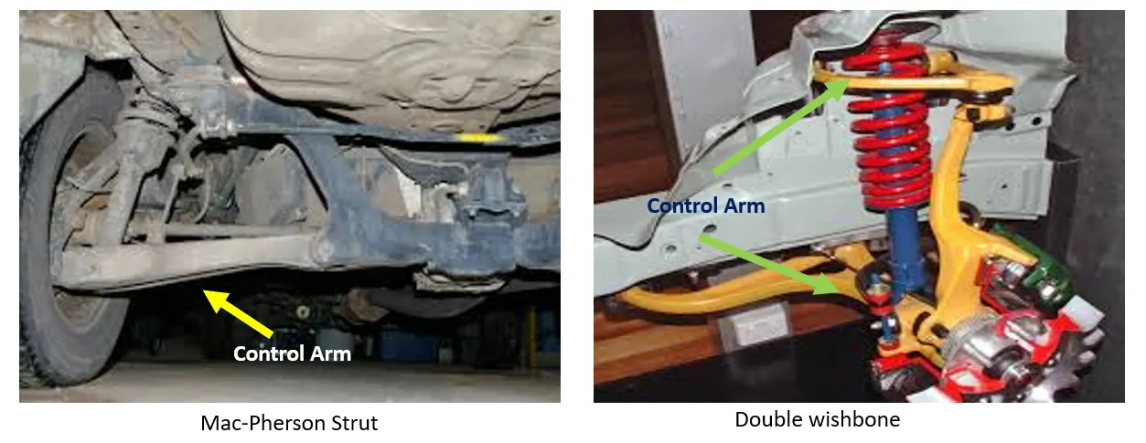
As you can see in the above image the Macpherson consist of only one Control arm whereas the Double wishbone includes two Control arms. Control arms are connected to the frame or body of a car through flexible rubber bushings, called Control arm bushing. This allows a control arm to swing up and down as front wheels roll over bumps and potholes. Bad knuckle arm results in Uneven tire wear, clunking noise, etc.
Ball Joint.
It’s a connecting part that connects the Steering Knuckle with the Control arm. The ball joint provides a pivot point in between the Steering knuckle and control arm which helps to control the vehicle smoothly and precisely.
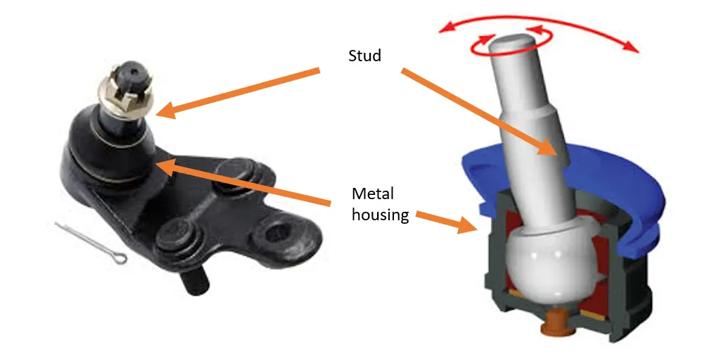
The ball joint assembly consists of Metal housing with the stud and bearing mounted inside. The stud can swing and rotate within the housing. The inside of the Ball joint feels with lubricant for frictionless movement.
The ball joint is the most crucial part of the suspension system. They were worn out after some time so the time to time replacement is needed. This will happen more often with double-wishbone as the forces (vertical forces due to uneven road/ bump/pothole) are transfer to the shock absorber via lower control arm ball joint only.
Suspension Spring
The suspension spring is there to absorbed the vibrations generated due to the bump on the uneven road while driving. It acts as a supporting member of the shock absorber. As we all know the spring has good force absorption capability because of its nature but they are not good to dissipate the energy stored during driving so they help the shock absorber to do that by providing extra support and make sure that no vibration will transfer to the cabinet. The secondary application of the spring is to maintain contact with the road during driving and cornering.
There are 5 types of suspension spring
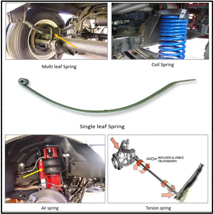
Shock absorber
shock absorbers are hydraulic (oil) pump-like devices that help to control the impact and rebound movement of your vehicle's springs and suspension. Along with smoothening out bumps and vibrations, the key role of the shock absorber is to ensure that the vehicle’s tires remain in contact with the road surface at all times, which ensures the safest control of a car.
The damping is depending on the principle of natural heat exchange. As the car move on the road, the suspension converts the up-down motion of the wheels (Uneven road) into kinetic energy by coil spring. As we know Coil spring is not good for dissipating this K.E., the Shock absorber does this work for the suspension system.
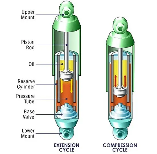
The shock absorber damped this K.E. stored in the springs using Hydraulics arrangement. As you can see in the above image when the piston traveled in the downward direction it will push the fluid down along with it, It will generate Heat as a high-pressure area get created at the bottom of the piston also the very small holes are on the piston that only allows a small amount of fluid to pass out under the high pressure. This heat later dissipated by natural cooling.
Procedure
The above-mentioned components are some of the important parts of the Suspension system, now it’s time to move with the actual model.
Here After importing we get the result as follows. The entire suspension assembly is enveloped in 3 PIDs only. As we can’t see any geometrical distortion in the model it is not necessary that the model is geometrically perfect for the meshing. We have to follow the ideal methodology.
I had followed the basic rule of methodology to check geometry and perform a Geometry check on the model.
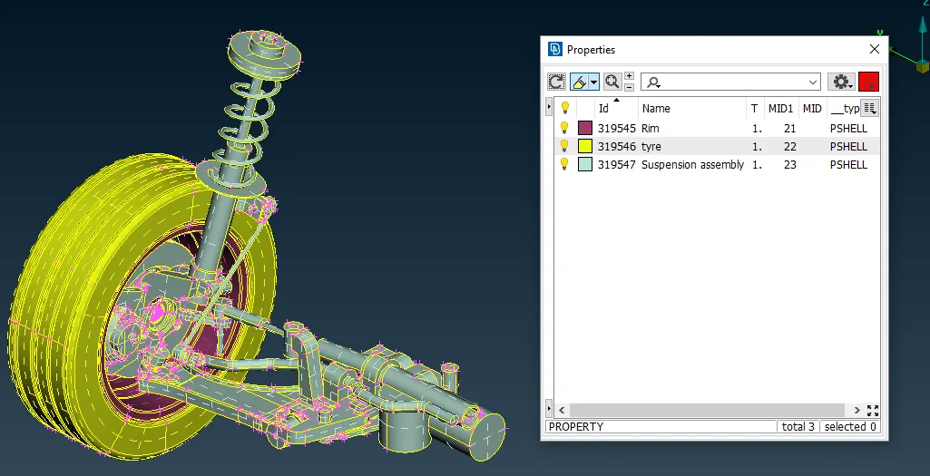
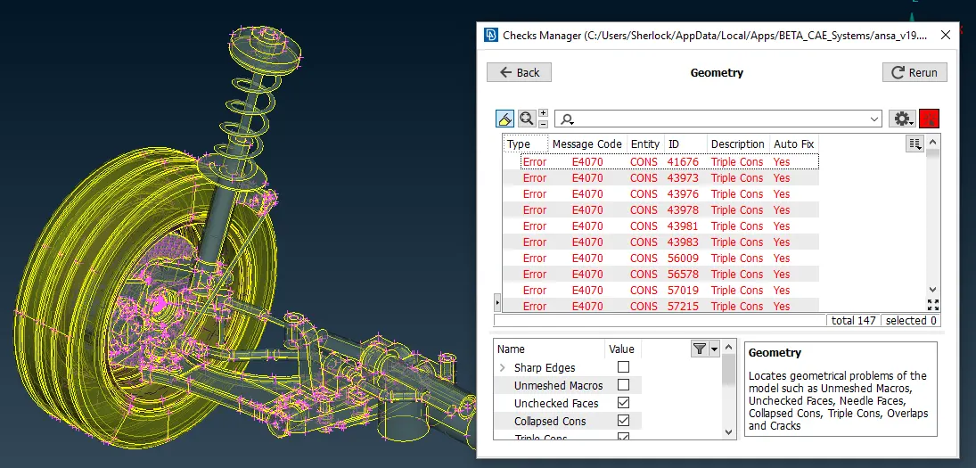
I had followed the basic rule of methodology to check geometry and perform a Geometry check on the model. The result I get as follows,
You can see the list of errors; this error list also consists of single cons which are further down in the list.
As you can get the idea from the photos of how large and compilated this assembly was, it’s better to practice to segregate such a large assembly and then go for a geometry check on each part individually.
After going through each part of the suspension system and segregated them into the different PIDs as per their category like sheet-metal/casing part/parts with thickness less than 5mm etc. I had got results as shown in the below image.
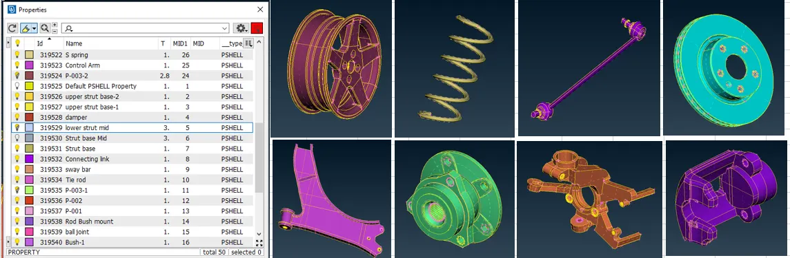
I had also differentiated the components which are gone a go under 1D, 2D, and 3D Finite elemental meshing. This has to be done in this stage because identifying the components depending on which category, they fall under it’s also an important step.
After separating the parts now, I am free to do individual geometry checks and clean up and I had done the same.
The result I get as follows,
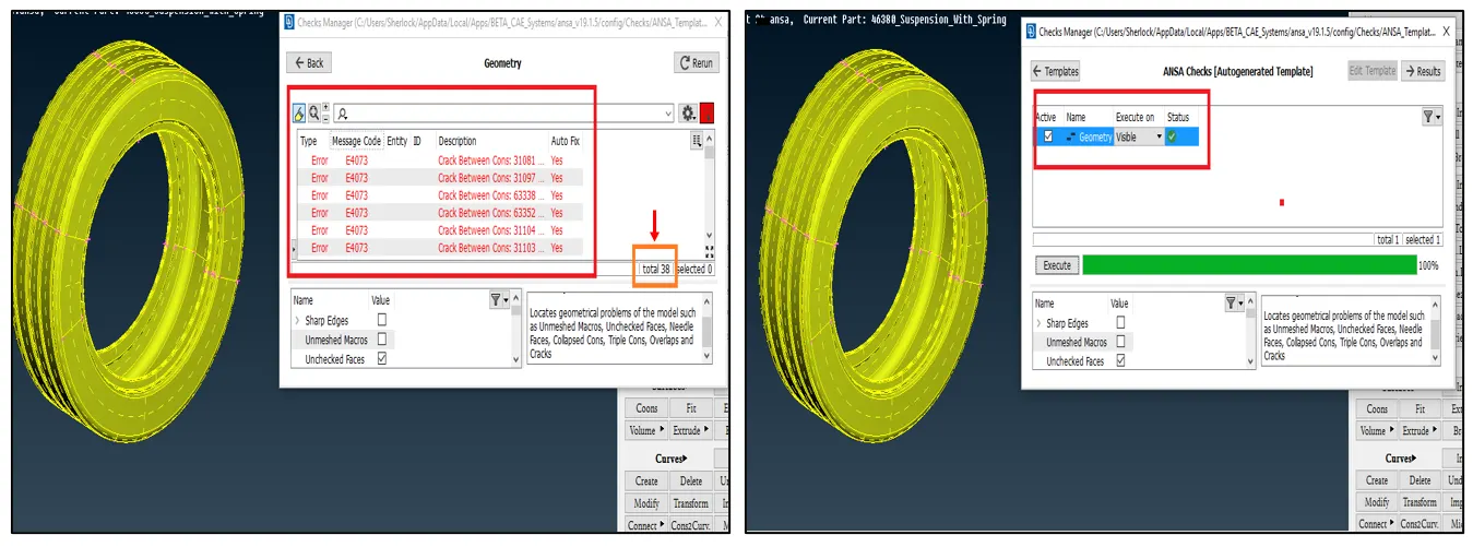
If you clearly see the image you can see the total numbers are error, I found of the wheel body was only 38 which is much lesser as compared to the result we get after performed a geometry checked on the entire assembly. It’s easy to eliminate also as there are no other components are here to disturbing the view, it is one of the advantages of saving parts in different PIDs.
I had done this for every component and clean the geometrical errors occurring in them. Here are some example screenshots,
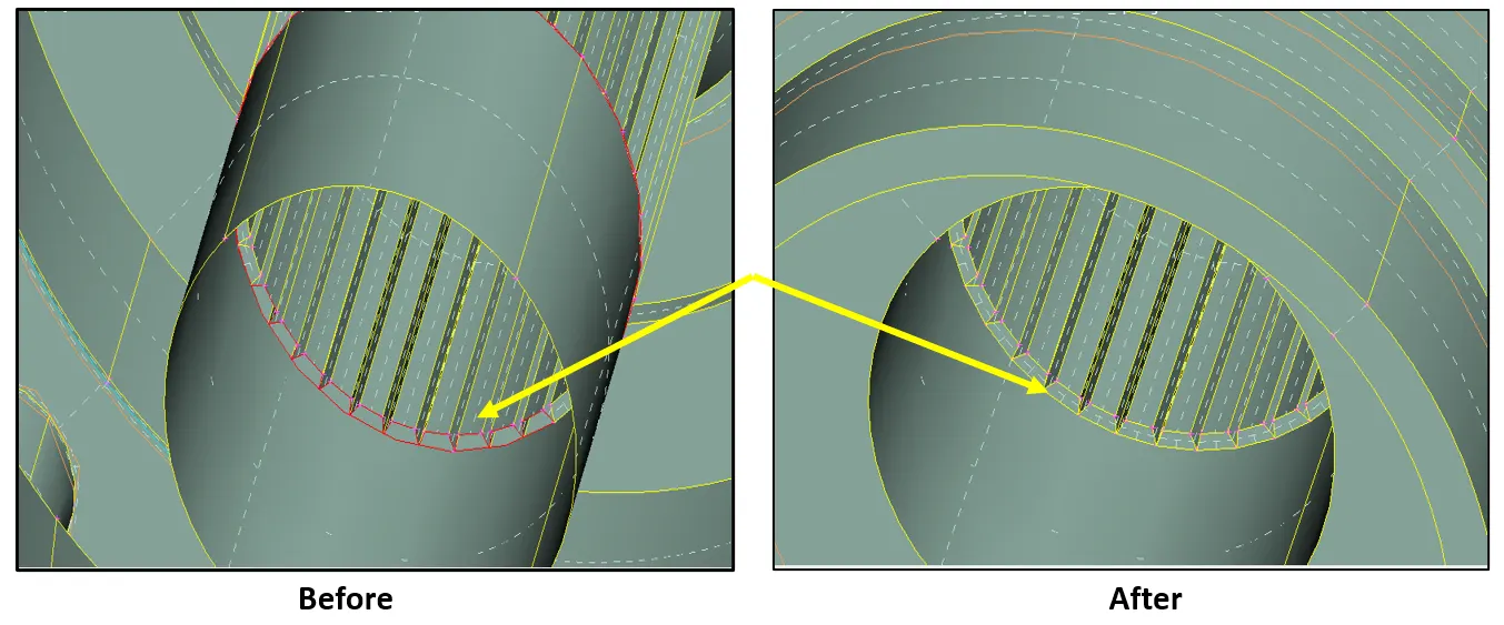
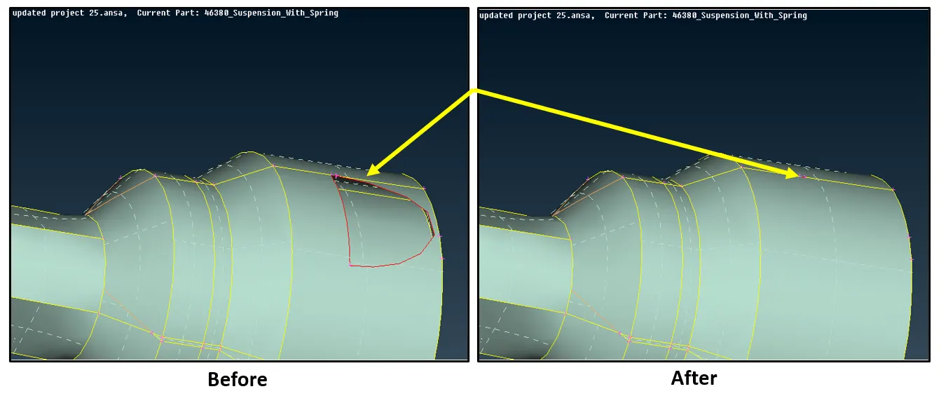
So, before I move to the defeaturing and meshing one important thing to note is there are two ways with which I can able to do defeaturing and meshing. First is the ‘Batch Mesh’ and the other is ‘Manual Mesh’.
Even though the batch mesh is the easy and completely automatic process I had decided to stick with the manual one. The reason was Defeaturing done by Batch mesh was not that good. It just leaves the open end near some features to satisfy the quality of a mesh which is not a good practice.
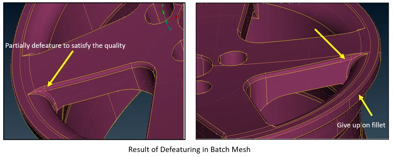
When we are deploying a 3D element for mesh it is mandatory to capture every small feature. The 3D mesh is there for capturing complicated features which is not possible to capture while doing 2d element meshing.
Here I get some Quality issues regarding maximum length, which is ignorable because the Quality criteria we set up for 3D element mesh are higher-level ones. Normally the criteria are very small. For example, here I take min length 5 for rim/wheel and 2 mm for other solid components, in the ideal case we take it as 0.2-0.5 mm so that the 3D element can capture every small feature available in the geometry.
The reason we are going with such high-Quality criteria is time-saving and system adaptability. Not everyone has a System with high specs. Also, the time taken to generate the mesh if we go with the smaller quality criteria is too large. The number of elements generated at the end of the process is also higher than that of what we obtained now. It will reduce further processing/simulation time. So, I was instructed to only focus on any Ted Collapse quality failure while doing 3D element meshing.
After deciding the method of defeaturing I moved we that only. I had Taken the component one by one defeatured where I see it was necessary and deploy Ortho tria and tria mesh on the component having thickness more than 5mm or on the component which is suitable for the 3D element meshing.
[Tria:- Deployed When the surface was flat plane one.]
[Ortho tria:- Deployed When the surface curved in nature/ geometry. This will give us better flow and pattern than the tria option]
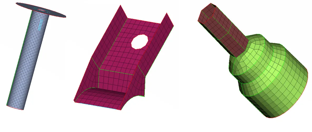
Whereas on the Sheetmetal component I went with shell elemental ‘mix’ type of mesh.
Here are some screenshots of Manual defeaturing,
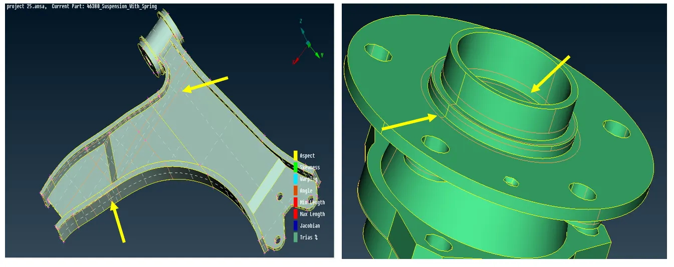
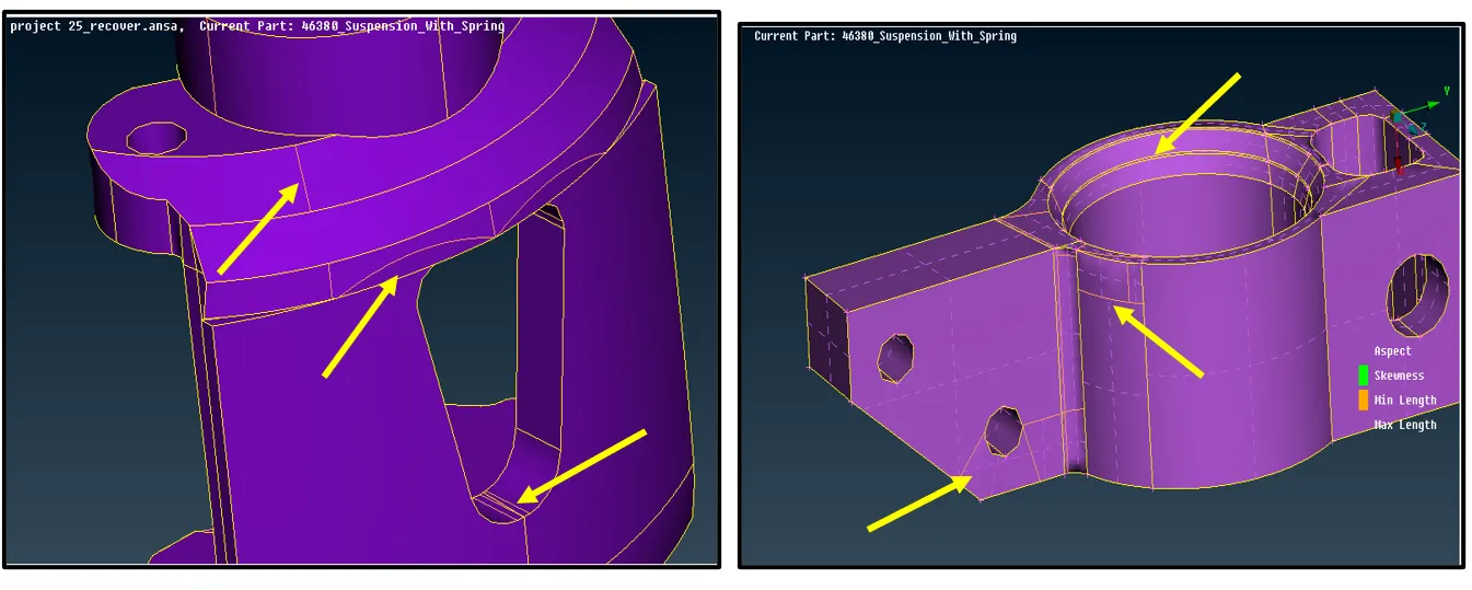
The arrows are pointed out where I had to do a defeaturing. You can see the orange lines they are the lines I neglected from the geometry. There too many construction lines on the surface of some parts that don’t have any relevance to any of the neighboring features, so I had deleted such lines that are not important to the geometry also create new ones in some areas where needed.
Introduction of Tetra Mesh/volume Mesh
After deploying the appropriate mesh on the appropriate components it’s time to create volume and fill that volume with the appropriate Tetra element. (here I am talking about the parts where I deployed ortho tria and tria mesh only. No parts with the mid surface will discuss in this segment)
- Tetra Meshing: - The tetra elements have 4 nodes as per the below image.
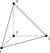
We are using tria mesh here and for a better flow pattern ortho tria on the outer surface of the part. So basically, on the surface, we do a normal Shell mesh but using Tria / ortho tria elements only. The basic idea is to create a close volume using shell mesh and then fill that volume using tetra elements which are nothing but 3d / solid elements.
These tetra elements only follow the surface mesh for the first layer of mesh then it just fills the entire volume without following any pattern that’s why it’s also called Unstructured Mesh. The inside tetra element doesn’t follow the surface mesh pattern through the geometry.
There is two option available for tetra meshing and each of them has their individual algorithms around which they generate the mesh.
- Tetra Rapid
- Tetra FEM
For this model, I went with Tetra Rapid because as per name indicates it did deploy the volume mesh rapidly on the other hand Tetra FEM takes a longer time than tetra Rapid.
The FEM mesh is more organized and sharp than rapid. Also, the number of elements generates during meshing is high in the Tetra FEM case.
The difference between the numbers of elements generated by both options is too high. That’s one of the reasons that tetra FEM meshing is more fine than Rapid and takes much time to do so. Also, these higher numbers of elements may cause trouble in the further analysis process as analysis will take much more time in the case of tetra FEM.
So, to save time I had decided to go with the Tetra Rapid option.
Now for deploying this tetra mesh we need a closed volume. So first we have to define the volume using the ‘V Mesh’ deck. For that, we just have to long-press the Define option in the V. Mesh deck then it will show two options manual and Auto, Go for a manual one.
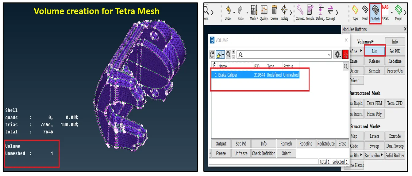
It will generate the volume and you can check that with the 'List' option which is next to the 'define'. Also, the volume data window will be appearing just below the shell data window [left side one]. As you can see it was showing volume unmeshed: 1. Actually, that means our volume creation is successful and we can move forward with tetra meshing.
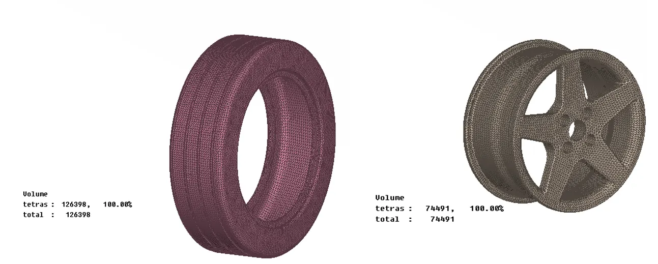
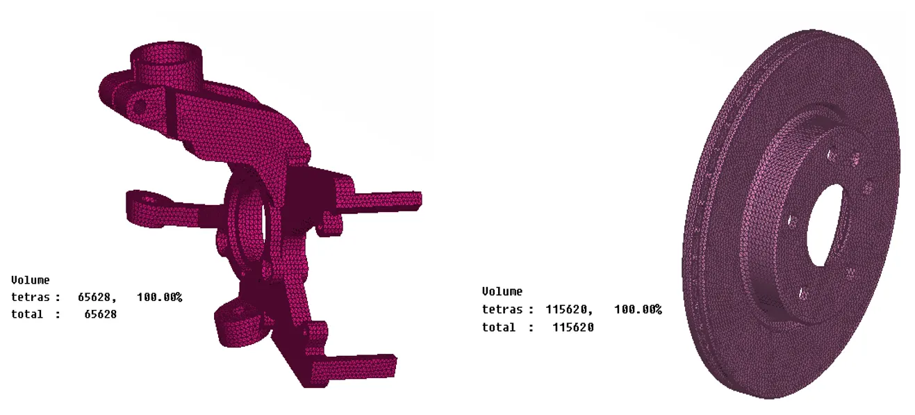
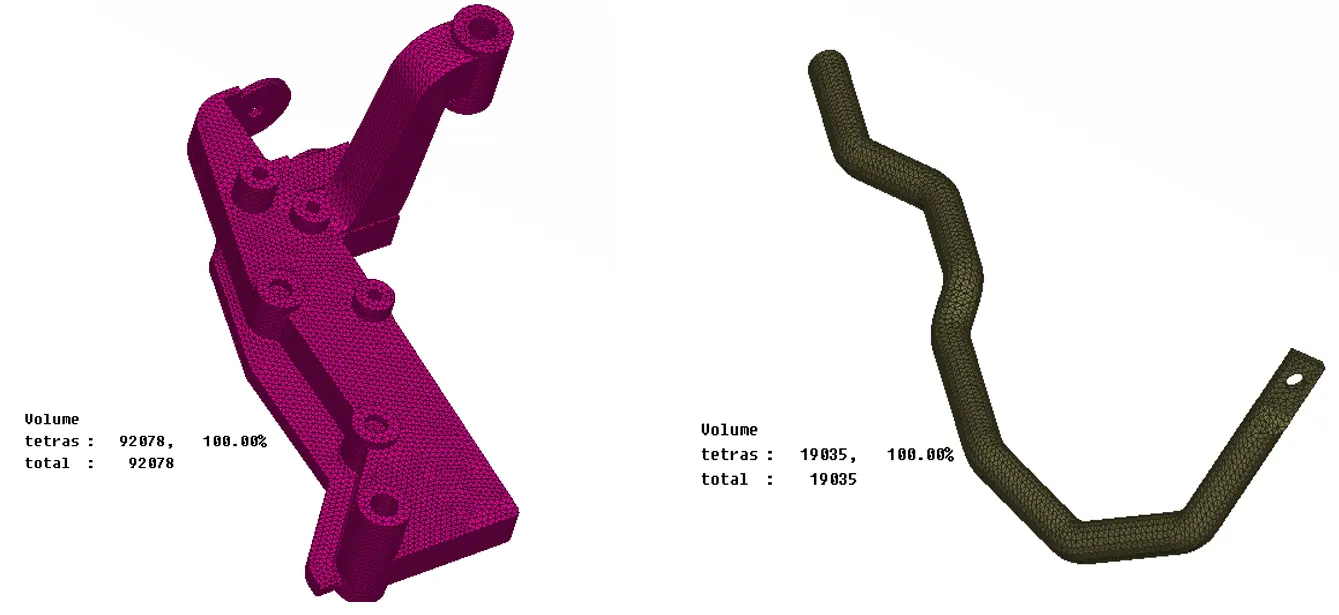
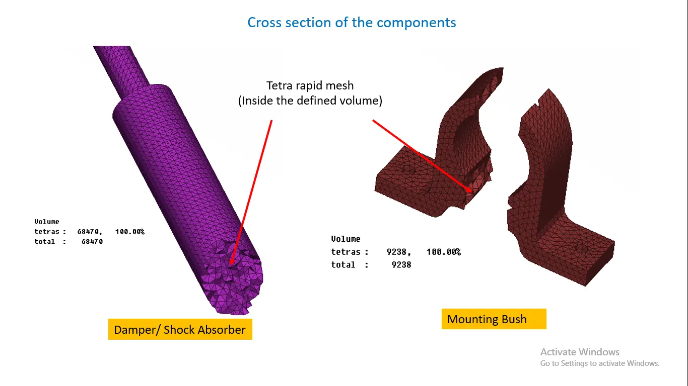
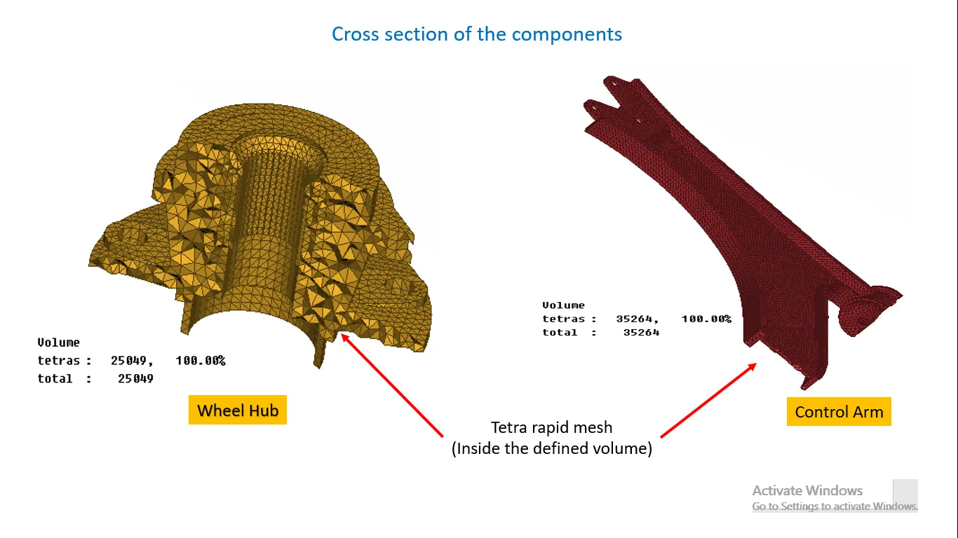
After successfully creating volume for every component I went for Tetra Rapid mesh and deployed it to the components which fall under the volume mesh category. Here I am sharing some of the screenshots of these components,
Mid surface 2D Finite element meshing
Now after deploying tetra mesh I had moved forward with the Connections process.
Introduction of Connections
Normally in-vehicle BIW there is a wide variety of connections are available to connect two-part with the same/different thickness to each other. Either by connecting them with Nut-bolt, Rivets, some time with welds (Seam weld & Spot weld) or we can go with Adhesives for some connections.
It's the Engineers' responsibility that assigns appropriate connections throughout the body without compromising the strength, durability, operation of the two adjacent parts.
Apart from this, there is a wide variety of decks available for analysis like Nastran for NVH [Noise-Vibration-Harshness], ABAQUS for Durability, DYNA for safety, etc. Each of them holding their connection properties that we have to take care of.
After analyzing the model, I get an idea about where and what type of connection I should be deploying over the model.
There are two ways we can Deploy the connections, one is the Manual method and another one is the Automated one.
Manual means we have to select holes like feature which are for nut and bolt connections and deploy the connection. Auto is normally used for deploying weld connections.
The benefit of Manual over Automated is The ANSA asked us where to store the connections and what name should be given to each connection which helps us to sort out connections on our will, but for a more complicated model automated one comes in handy.
The data of connection get stored in two different areas depending on which method you are using. As I said earlier with the manual method [Spider/cluster connection, rigid connection,] ANSA asked us where to store the connections and what name should be given to each connection. You can save the data in "Model Browser" and get access to all stored connection data at any time.
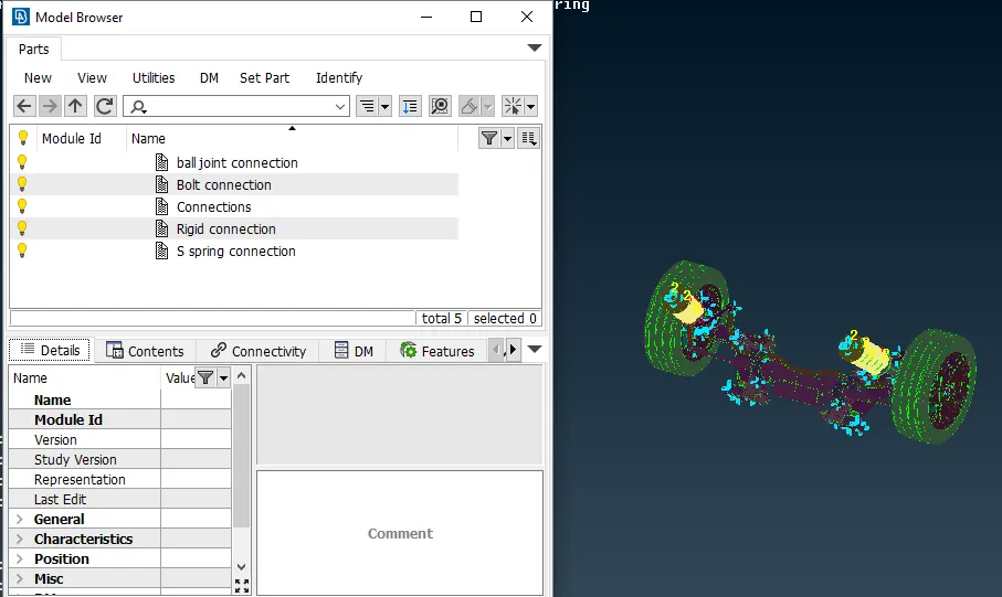
here as you can see, I made a new file for every type of connection like for bolt connection/rigid connection where I stored all connections in the model.
I just made a new folder named '' Connections" to store the data.
The Data of connections that are made by the Automated method automatically get segregated to the Database to their respective folder.
I had deployed the connection using NASTRAN Deck, and the result I got was as follows,

I had to deploy a Rigid connection in the center because the usual bolt connection was not possible due to the geometry’s alignment mismatch. As per the standard procedure, the wheel hub assembly (consist of the Steering knuckle, Brake disk. Caliper) is responsible to keep the wheel in the position in the car. The wheel gets connected to the car body by the wheel hub itself. Here as you can see in the above image the alignment gets shifted and mounting holes are not in the position so we can’t deploy the bolt connection over there. So as per the discussion with the seniors I had deployed a Rigid connection in middle to hold it during the Simulation. The other thing is this model would go for NVH simulation and moving connections are not necessary for NVH simulation.
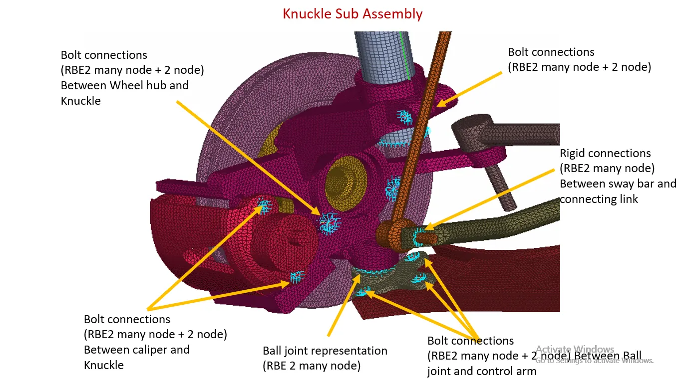
Here also there was a missing part in the ball joint. We only got the frame of the ball joint for this project and the stud and bearing part was missing, so after a discussion with the seniors, I went with the rigid connection which will hold the Knuckle and joint during the simulation.
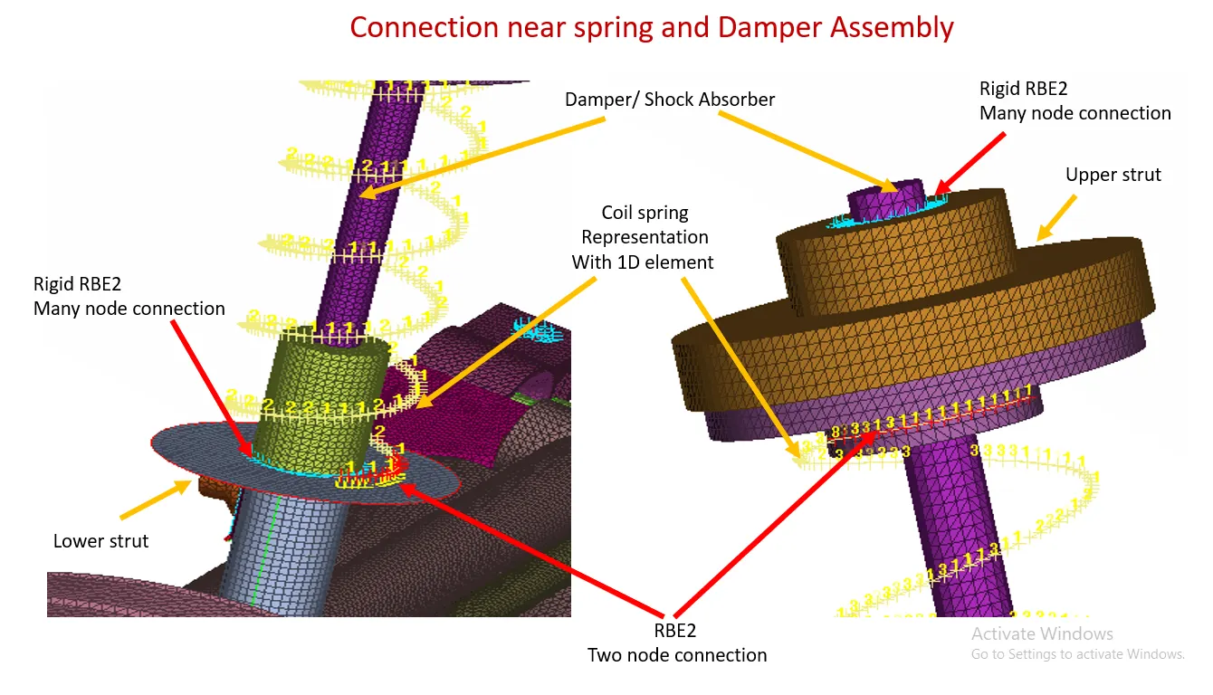
Here I captured the Coil spring as a 1D element that why is seen as the above image.
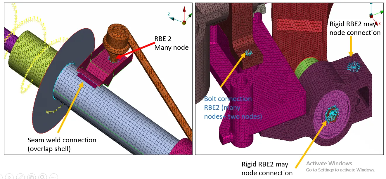
The connection marked with the red arrow in the above image was unique because I was a first-time encounter with such a connection. The unique thing about this connection is here I had connected a connection between 3D FE with 2D FE. Before this, I had only worked on projects having either solid or 2D element mesh. This was my first experience working with the combined one. Even though the connection was a normal RBE2 rigid connection.
The Final result
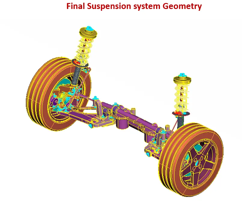
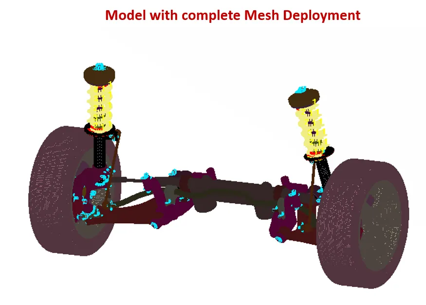
Conclusion: -
- 3D meshing/volume meshing / Solid meshing only done on the part which has a thickness of more than 5mm and the casting parts.
- The End result manual meshing is more accurate, in terms of defeaturing because in some cases Batch mesh won’t do defeaturing correctly and that eventually lead to bad meshing or quality failure.
- The Min. length and Max. length criteria wouldn’t get applicable to the solid mesh as the elements are 3D elements in nature and we can’t define them on the basis of 2d perimeters. Though we have to check Tet collapse for 3d elements.
- If there is no sufficient data available over the particular connection, the designer should assume that and free to do connection on its own but 90% of the time a rightful data is given to the engineer for connection.
- The Types of connection and DOF of the connections are dependent on the type of Deck we are gone use and the type of simulation we are gone performed. As the Type of simulation changes, the connection type, and their respective Connection deck also change.