SUSPENSION SYSTEM
AIM:To perform 2D meshing in the area where mid-surface is being extracted and 3D volumetric meshing where the thickness are more than 5mm along with connection deployment at a given quality criterion in a given model.
THEORY:Suspension is the system of tires, tire air, springs, shock absorbers and linkages that connects a vehicle to its wheels and allows relative motion between the two.The suspension also protects the vehicle itself and any cargo or luggage from damage and wear.
Wheels and tires
Tires aren’t always considered part of the suspension, but they’re arguably the most important component of it. Tires provide traction for acceleration, braking, and cornering, and they absorb small bumps.
Tires wear over time, and are subject to cuts and punctures from hitting sharp objects, and to slow or sudden leaks from impacts. On the other hand, wheels fail (from bending or cracking) much less often, usually only in response to hard impacts from accidents or hitting potholes.
Springs
Every car and truck today has some sort of mechanism to absorb large bumps, and this always includes some form of spring, a metal part that bends in response to force have used torsion bars — metal rods that absorb impacts by twisting instead of bending — instead of coil or leaf springs, but these are all different forms of spring.)
Springs can sometimes break when the vehicle hits a bump very hard, and many will sag eventually (after many years), but in general these parts are much less prone to failure than most other suspension components.
Shock absorbers and struts
While springs absorb the bumps, shock absorbers (or, in cars that have them, struts, which are similar to shocks) dampen the motion of the springs after a bump, keeping the vehicle from bouncing excessively.
Shocks and struts are filled with a thick oil, and over time the oil can leak out, causing the shock or strut to fail. Impacts and accidents can also cause leakage or can damage delicate internal parts.
Linkages
Every suspension includes various rods and other connecting pieces that collectively keep the wheels where they’re supposed to be relative to the rest of the vehicle. Most of these linkages are solid metal parts that rarely fail except in major accidents. However, sometimes linkages and associated bushings are sold together, and the failure of a bushing can necessitate replacing the whole assembly.
Bushings, bearings, and joints
Because most parts of any suspension must be movable, the various linkages are connected by flexible connections. These include bushings and bearings, which are connections that allow a small amount of twisting or sliding, often without needing lubrication, and joints, which in automotive applications often use a lubricant such as grease to allow for controlled movement.
Some suspension bushings are made of rubber, which can become brittle or break over time, leading to failure. Many joints tend to wear out, leading initially to looseness and eventually to failure. A couple of the most common culprits are tie rod ends, which are lubricated joints that connects certain steering linkage parts, ball joints, which are found in both the steering system and attached to the control arms, and the bushings that separate the control arms from the vehicle’s frame.
Steering system — all types
Every steering systems contains numerous linkages, some joints such as the tie rod ends mentioned above, and some sort of steering box, the mechanical device that converts rotation of the steering wheel into movement of the car’s wheels.
In general, linkages aren’t very likely to fail, while components such as tie rod ends are. Steering boxes wear out eventually, with rack-and-pinion steering systems in vehicles equipped with hydraulic power steering being the most failure prone.
Hydraulic power steering
Many vehicles are equipped with power steering. Of the two types of power steering, hydraulic systems (i.e., those that use a high-pressure fluid to help the driver turn the wheels) are more failure-prone. Fluid can leak from high-pressure lines, delicate valves occasionally wear out, the belt that drives the power steering pump can loosen or break, and eventually the pump itself may fail.
Electric power steering
More and more power steering systems found in modern cars and trucks are electric, not hydraulic. Electric power steering systems include various sensors, wires, and actuators (motors), any of which can fail, but luckily such failures are less common than failures of hydraulic components.
That’s a lot of parts, but it can be simplified into the following rule of thumb: softer parts wear out more quickly than harder ones, and wet ones more than dry ones. Thus, for example, a soft rubber bushing that has to change shape with every bump will probably need replacement (from wear or complete failure) before a solid metal rod will, and a shock absorber that contains fluid is more likely to fail than a metal spring.
PROCEDURE:Firstly needs to check the geometric error in the tyre and the rim section and making the geometry 100% clean .
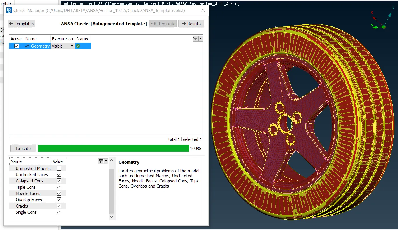
Then needs to check quality and meshing criterion:
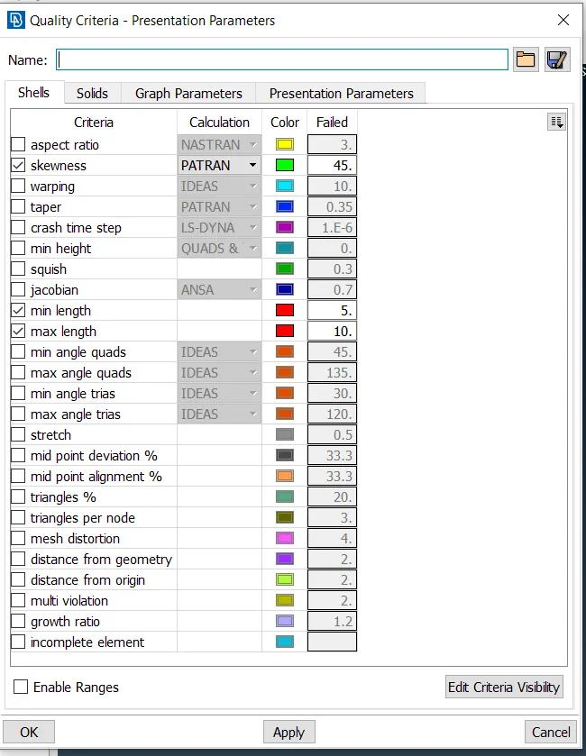
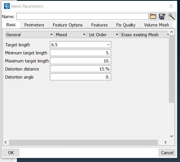
now we have to give spot meshing in shell meshing in mesh mode and using reconstructuion and smooth we got to have the refined geometry, the areas where the surfaces are flat we put trias over and the curved region preferably be having a ortho trias ,but even if we deployed a trias in the curved faces it is not considered to be a wrong but capturing of the model is not that accurate.After completion of shell meshing we proceed with the volumetric meshing ,in the volumetric mesh mode volume-define-manual.Tyre and RIM got assign and in the list we gave it remesh both TETRA-RAPID and TETRA-FEM both will give the respective result of volume either is fine.
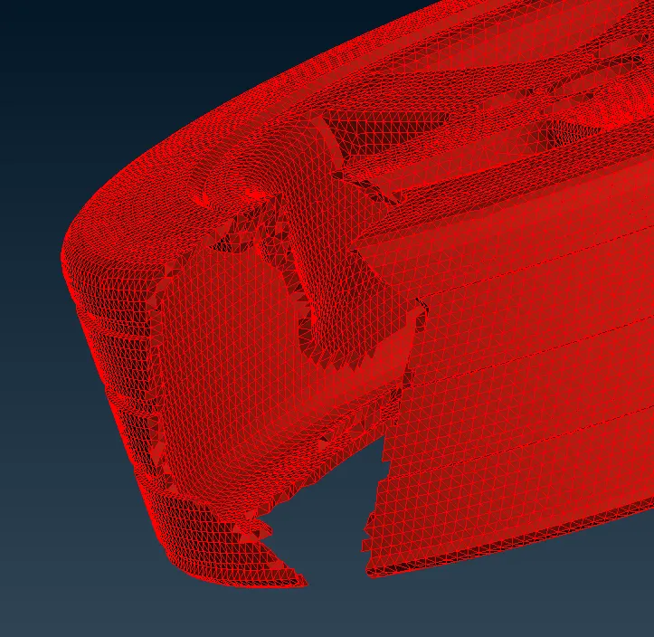
In the wire frame mode it is cleared and easily visualised that volume mesh has been constructed.
Now moving ahead further firstly we have to assign a lot of PIDS for the different different parts of suspension assembly by this its get differentiate where to perform 2d and where to perform 3d meshing.So PIDS are listed below:
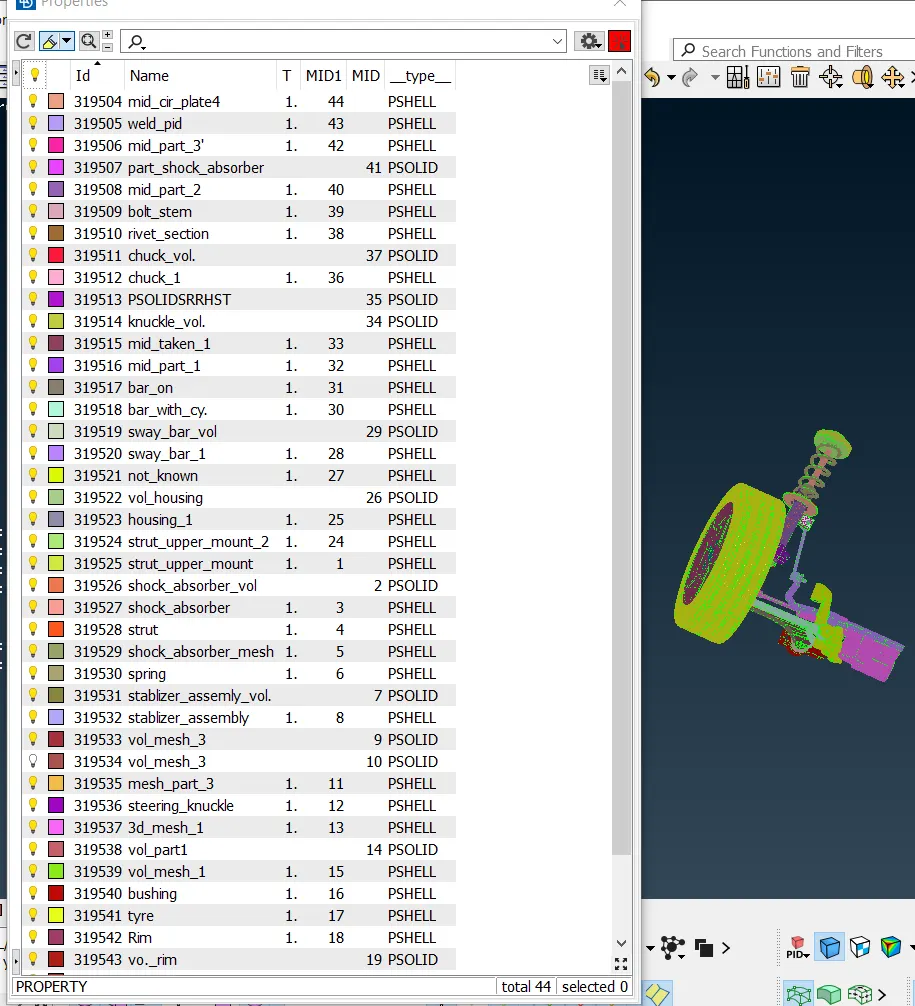
Now from above its very cleared that we have seggregated the models into many PIDs .Now we have to check the geometric errors for each PIDs and make it 100% clean.And the quality criterion and the meshing criterion for the 3D meshing for suspension are :
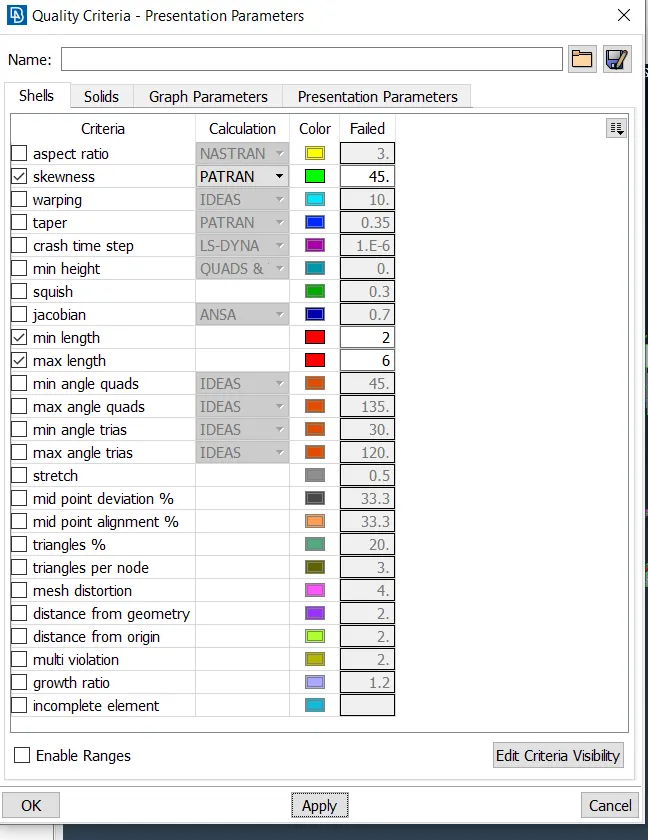
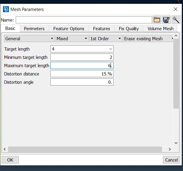
Now the quality criterion and meshing criterion for the 2D MESHING for rest of the part i.e excluded tyre and rim are :
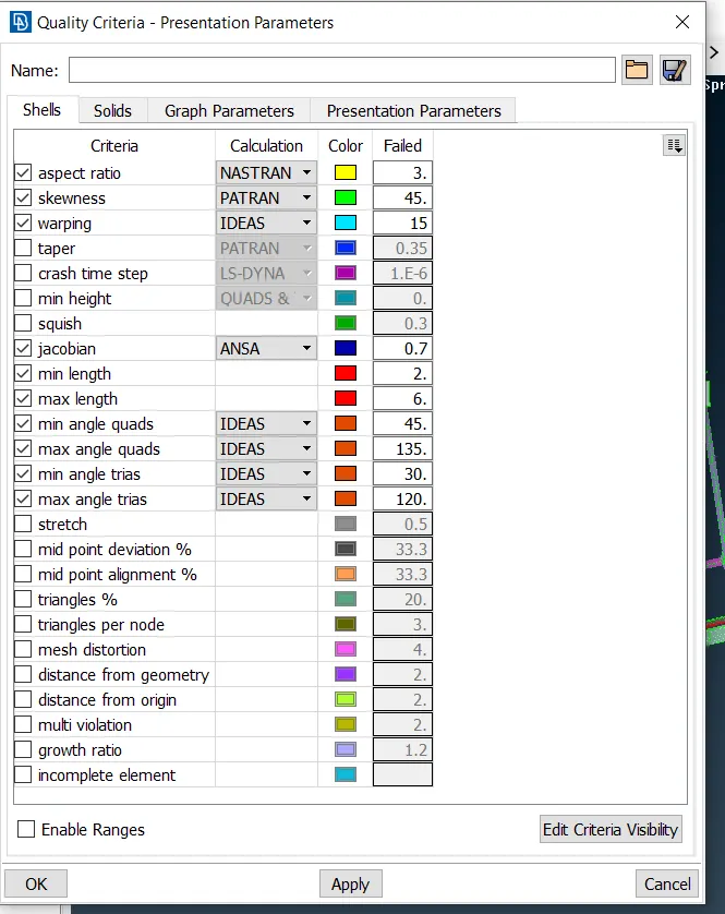
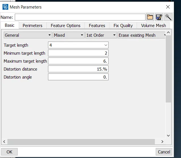
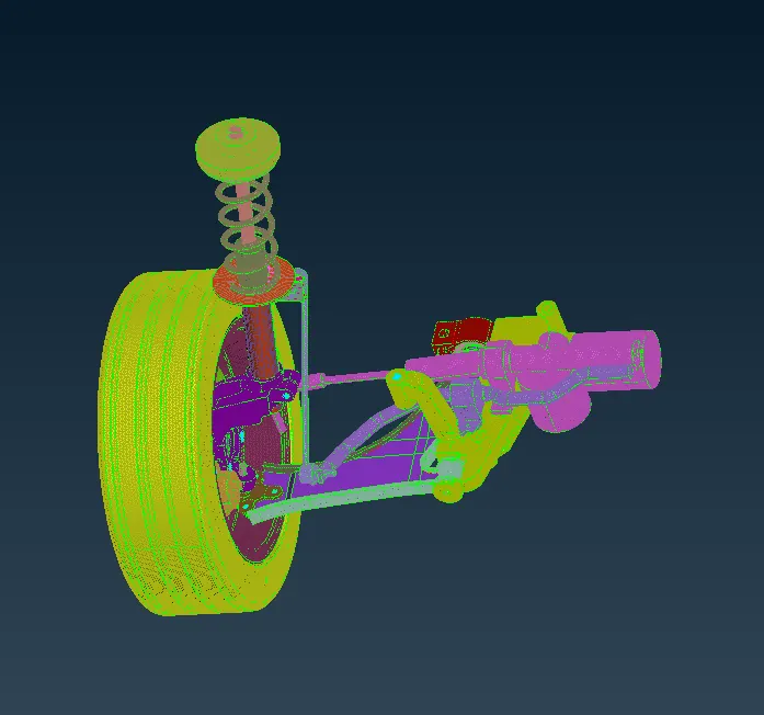
Following such steps stated above the model we have got from it :
List of volume which we got while doing the 3D volumetric meshing are :
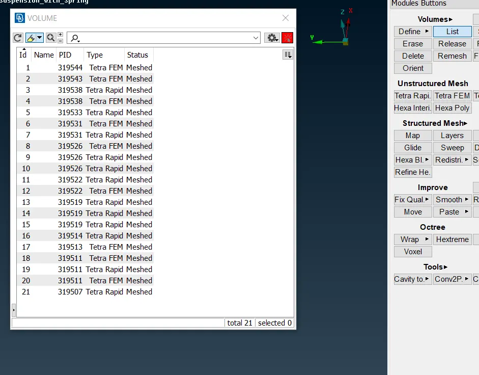
In 3D meshing the main concern is tet-collapse which can be removed by move-free option available in GRIDS in mesh mode .Its preferable to have a good quality of mesh with lesser amount of off elements.
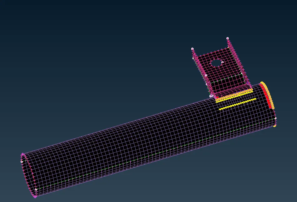
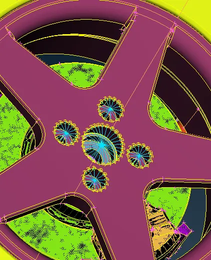
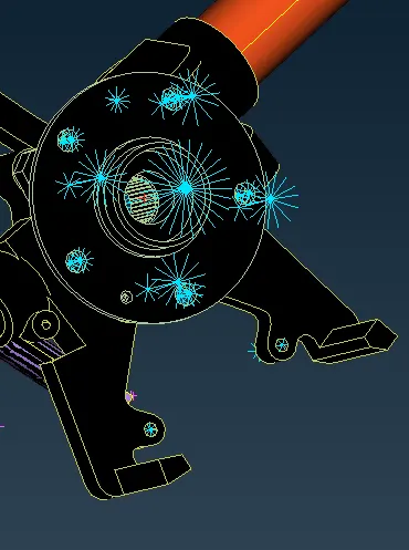
Moving on to the connection deployment wherever we find the 2 surfaces are parallel to each other we deployed a overlap shell weld and in case of the surfaces are perepndicular we got to go with Y-joint shell weld.And the region where it is supposed to have bolt and nuts assembly we should go for the RBE2 rigidised method it could be a cluster or may be rigidised are connected with spindle connection.For the weld formulation we create a curve using feat2 curve option in perimeter in mesh mode realising it with seamweld and deployed the automatic connection assigning P1 and P2.
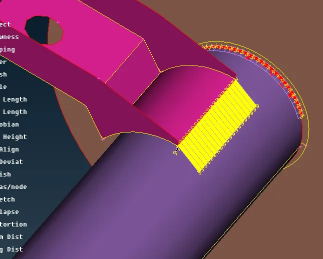
in this image shows the deployement of weld while parallel surface and while perpendicular surface on the top of it.
Now the shown below image shows the rigidisation by RBE2:
CONCLUSION:(a) By this got to know about the method of 2D and 3D meshing and how to club them together.
(b)Also knew about the different connection deployment such RBE2 connection ,seamweld connection also in some cases spotweld connections too where we have to deployed the RBE3-HEXA-RBE3 connection.