DRAWING SHEET PREPARATION & PART DETAILING IN CATIA
DRAWING SHEET CREATION FOR PART MODEL
AIM
The Aim of this challenge is to draw a detailed drawing sheet from the 3D part created using part design work bench
DESCRIPTION
Engineering Drawings are representation of geometrical objects on the drawing sheet and is used to define the requirements of engineering items. Thus it is a medium of communication between Designer, Manufacturer and Inspection.
The Engineering Drawing has to adhere to accepted standards
Mostly ISO standards are followed
The Drawing Sheet has
- Title Block
- Description Box
- Bill Of Materials
- Standard Views
- Annotated texts and symbols
PAGE LAYOUT
The Engineering Drawing sheet has standard layout (ISO) as
A0 841 x 1189 mm
A1 594 x 841 mm
A2 420 x 594 mm
A3 297 x 420 mm
A4 210 x 297 mm
B4 250 x 354 mm
B5 182 x 257 mm
DRAWING SCALE
To accommodate in the standard drawing layout the represented objects which are large are reduced and small are enlarged vice versa and the scale is called reducing scale/enlarging scale and ratio is called representative factor.
R.F = Dimension of Drawing/Dimension of Object
DESCRIPTION BOX
The details of standards used in the drawing sheet are mention in the bottom of the sheet layout which tells the engineer how to approach the Drawings
REPRESENTATIONS
The Engineering Drawing sheet is a graphical 2D depiction of 3D part model and has drawing views namely, Front View, Side View, Top view and Isometric View
Isometric view the angle between the principle axes are 120 degrees apart and give better representation of the model
All the Geometric representation and notations are done in the Orthographical views that translates information to produce a part
At times the standard views are sliced and put separate to provide better understanding like
- Section View
- Section Cut
- Detail View
The line styles followed are
- Object Line
- Hidden Line
- Center Line
- Leader Line
- Extension Line
- Dimension Line
- Center Axis
- Section Plane Lines
- Break Lines
GDT
Geometrical Dimensioning and Tolerance standards are the way of symbolic interpretation used to convey the standard to manufacture with suitable size and dimension and fits
The Tolerance Standards, Control Frame are also mentioned in the sheet
RULES FOLLOWED
The Drawing views are clear and are not intersecting other dimensions and views
The Views should be proportional and adhere within the sheet layout
The Dimensional Lines should fully define the geometry
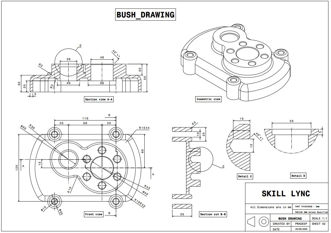
BUSH DRAWING
- The Bush part that is produced in CATIA part workbench is drafted into the Drawing work bench
- The Front view is fixed with suitable RF factor and all the projected views are taken out
- An Isometric View of the Bush is also included
- The complicated drawing representations are provided in separate section view by not congesting the views
- The Detail views are used to magnify the portions to give better picture
- The General Notes and standards are provided in the Description box bottom right corner
- All the views are ensured to contain in the layout and file is saved
The Image of the drawing sheet is attached below