Project 2
REPORT:
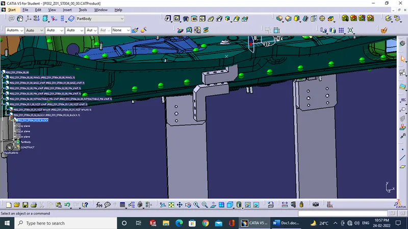
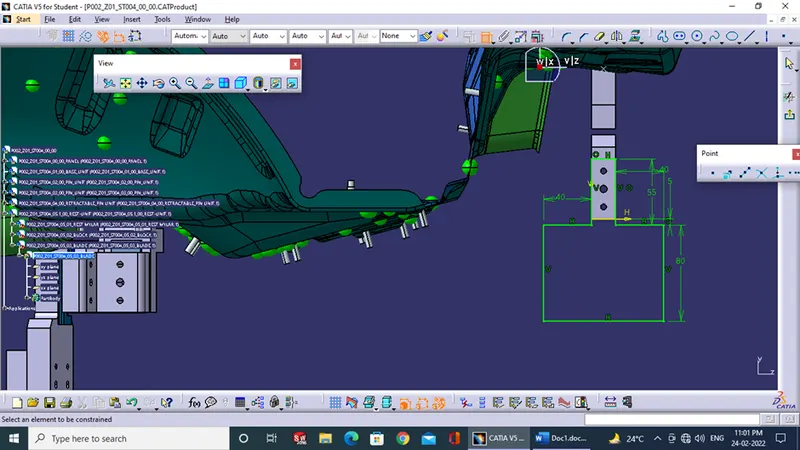
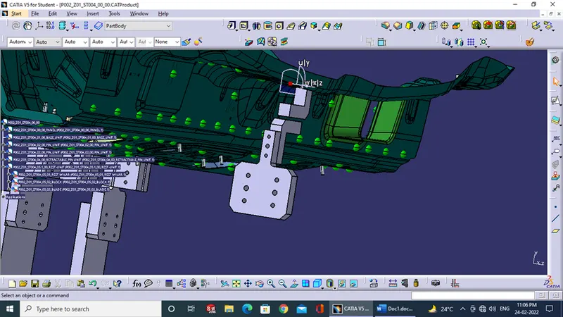
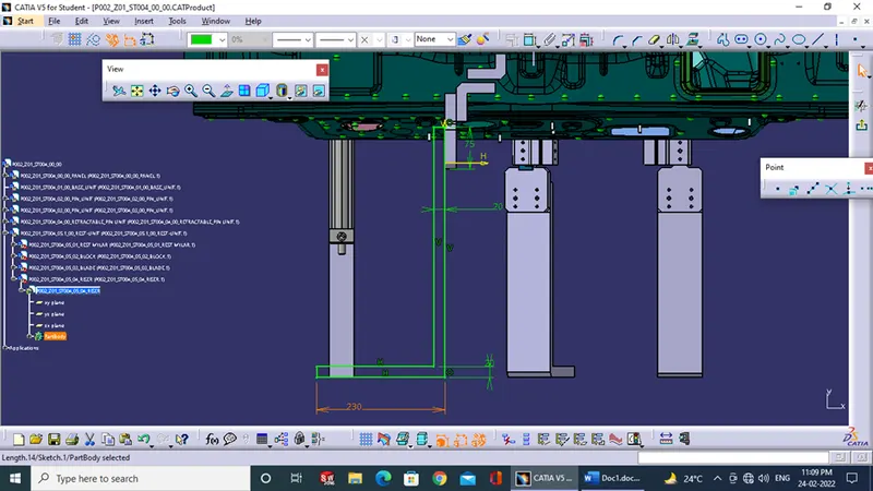
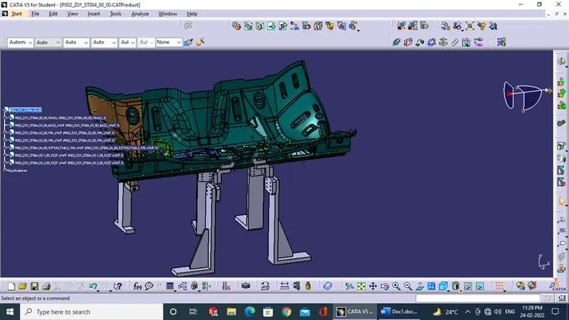
The process for designing a BIW fixture for the given component is as follows:
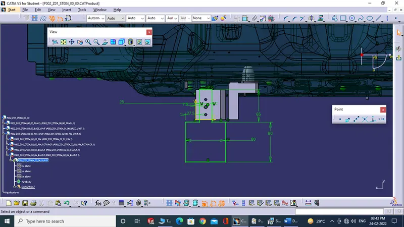
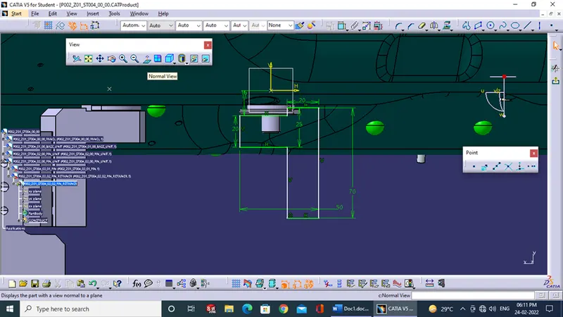
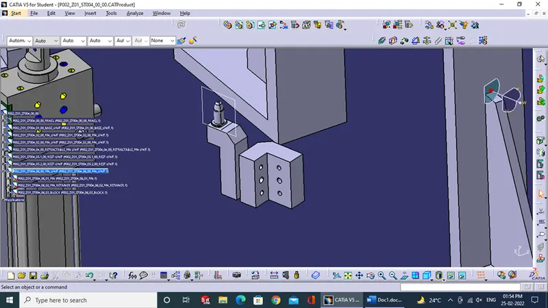
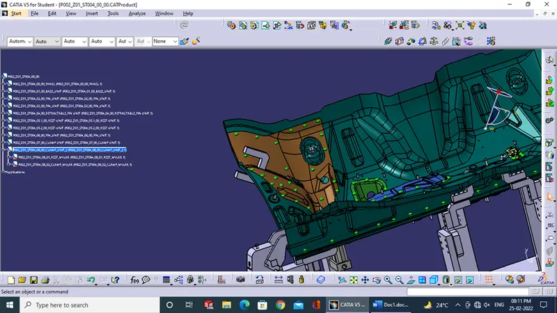
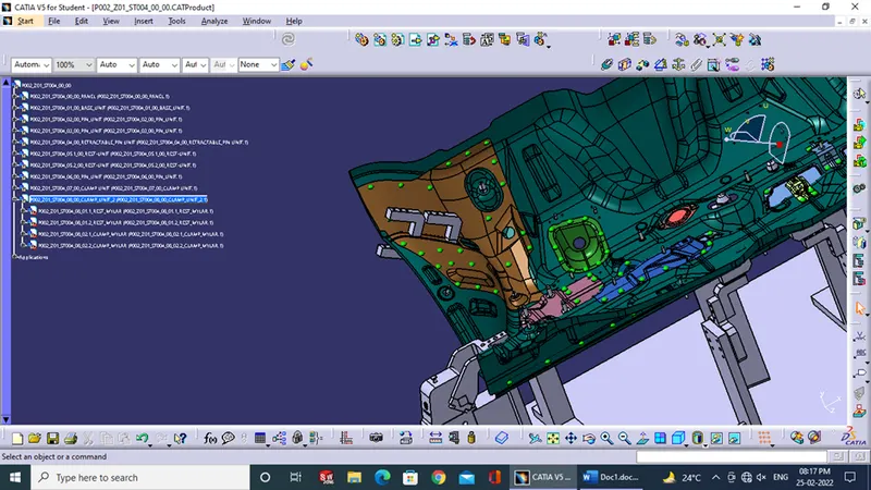
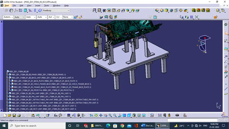
1.) We should study the panel given as in this case it was the BIW component for IP console which has multiple parts welded onto it using a spot welding process.
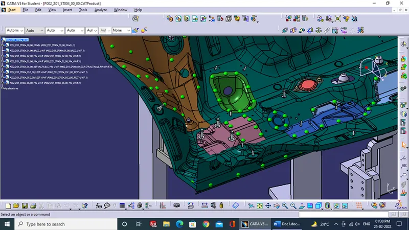
2.) Using the 3-2-1 principle for all the components of BIW, the degree of freedoms of components were constrained.
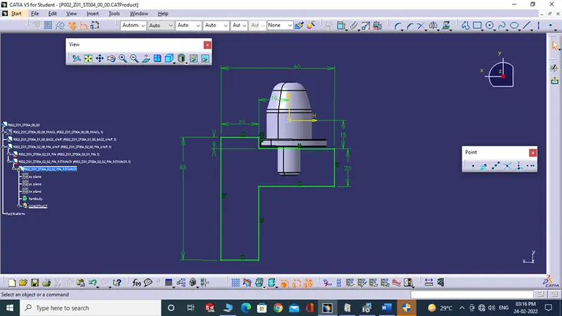
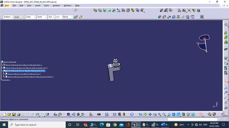
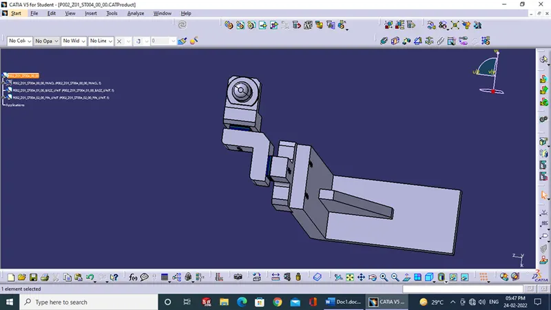
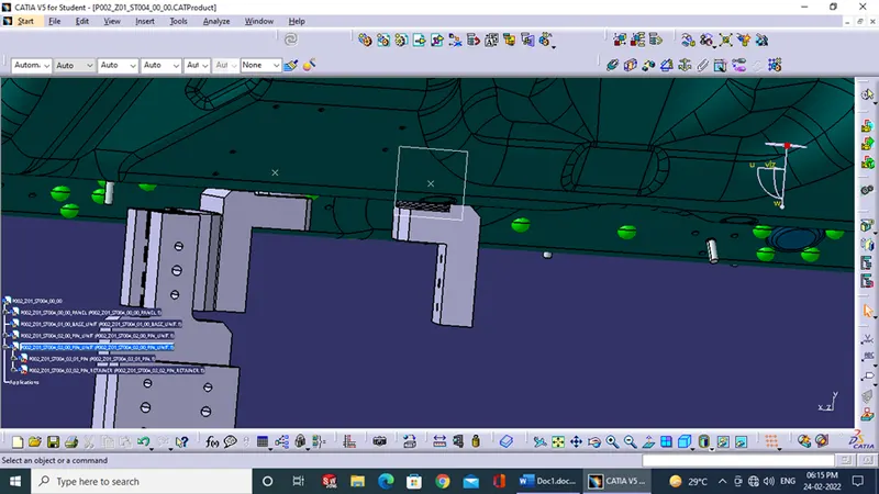
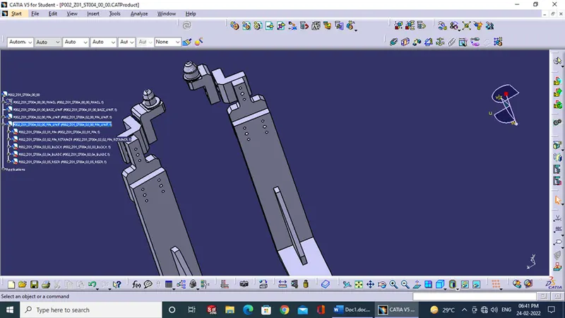
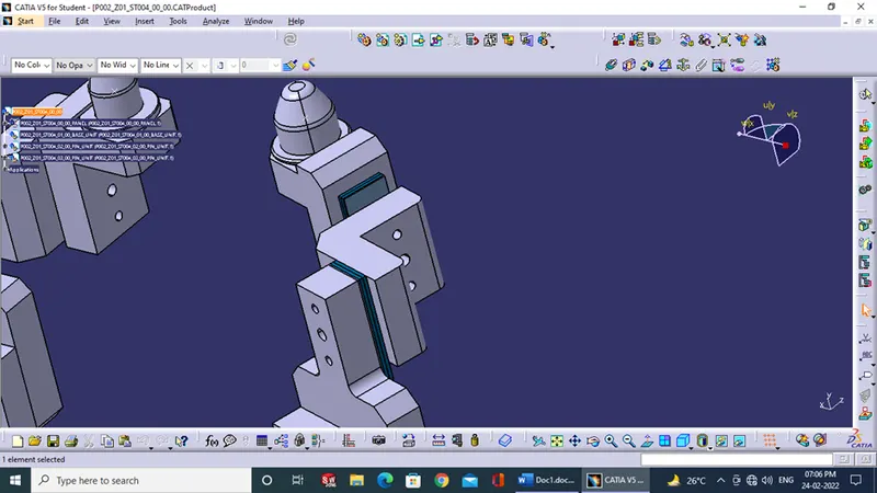
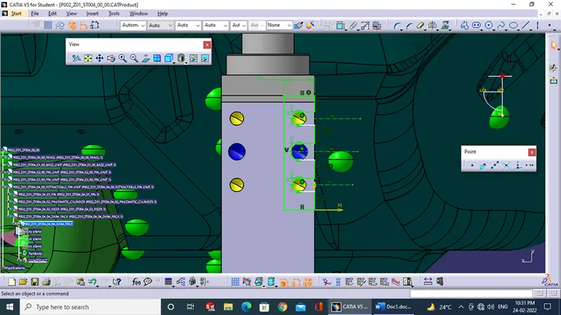
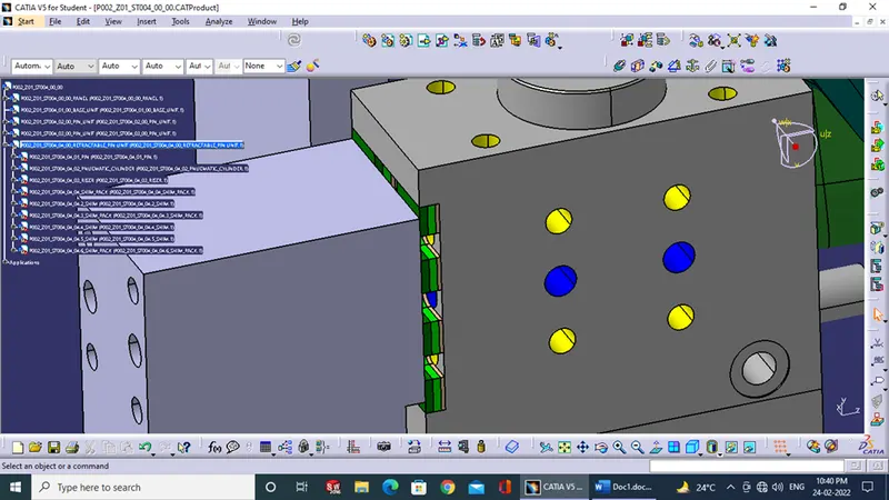
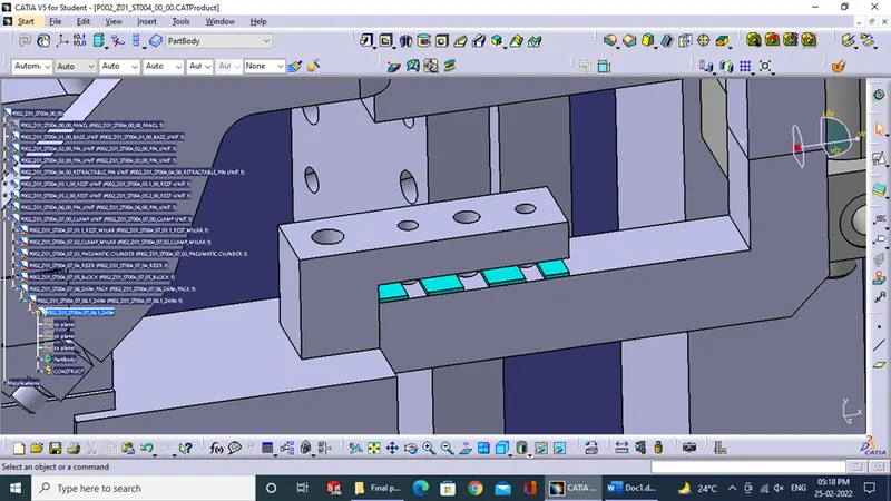
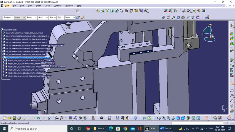
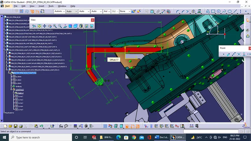
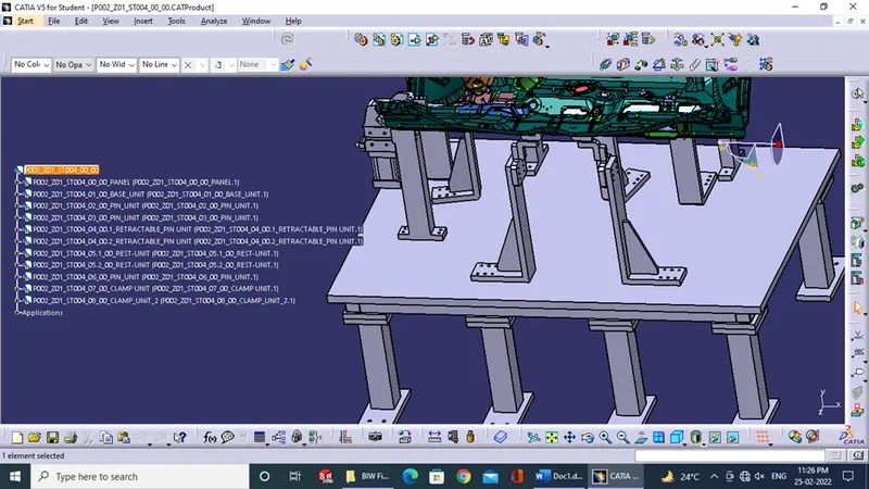
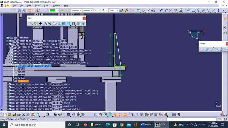
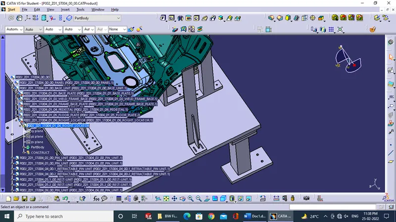
3.) At first clamps were used to constraint 6 DOF were constrained after then 2 pins were inserted for constraining 4 dof and then, at last, a clamp unit is created to constrain the movement in the remaining 2 directions.
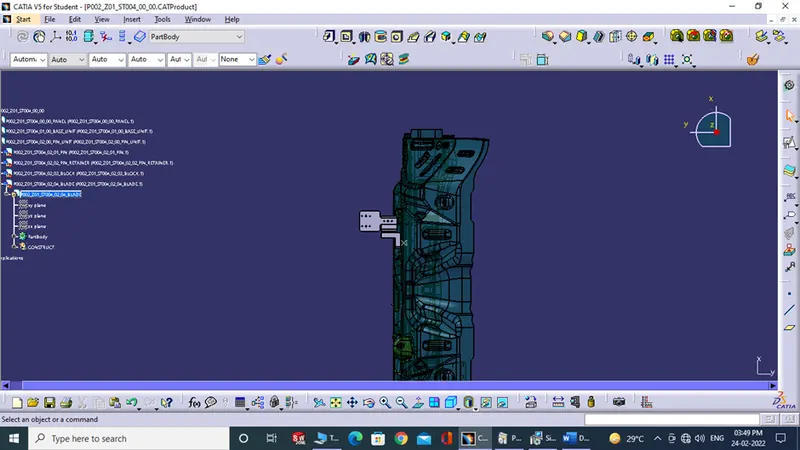
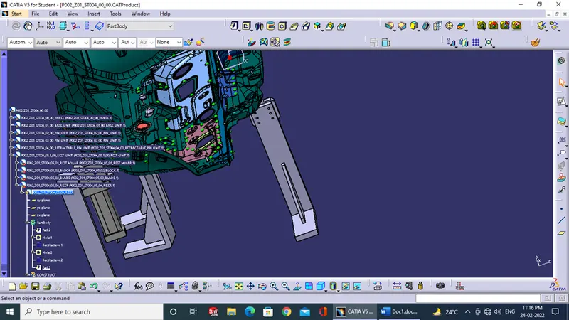
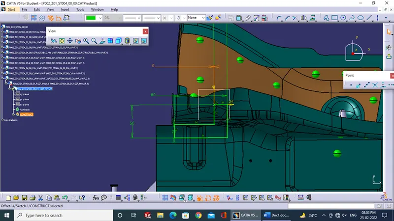
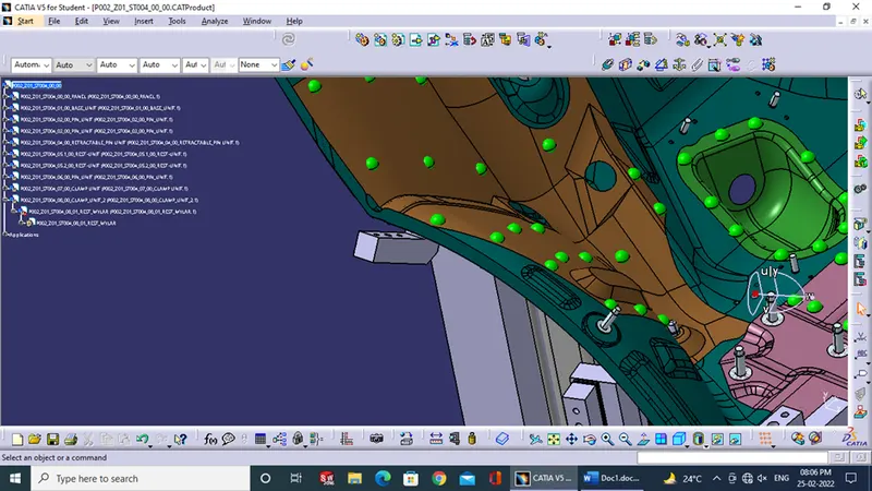
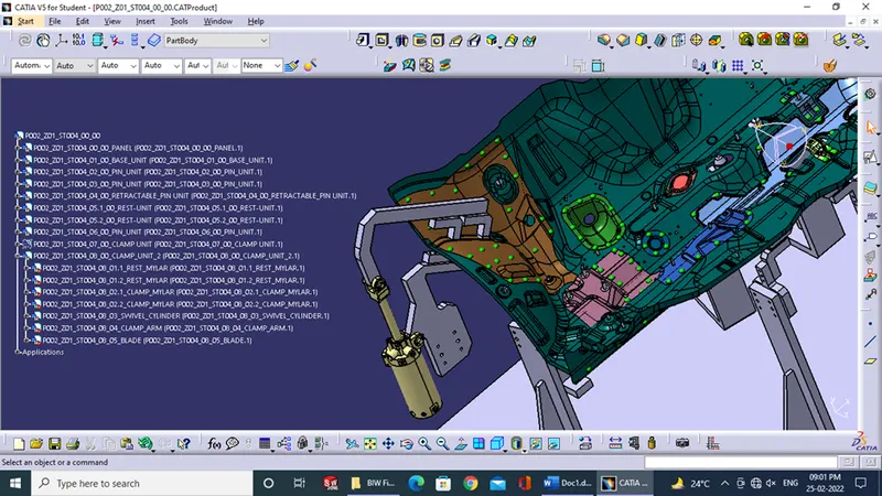
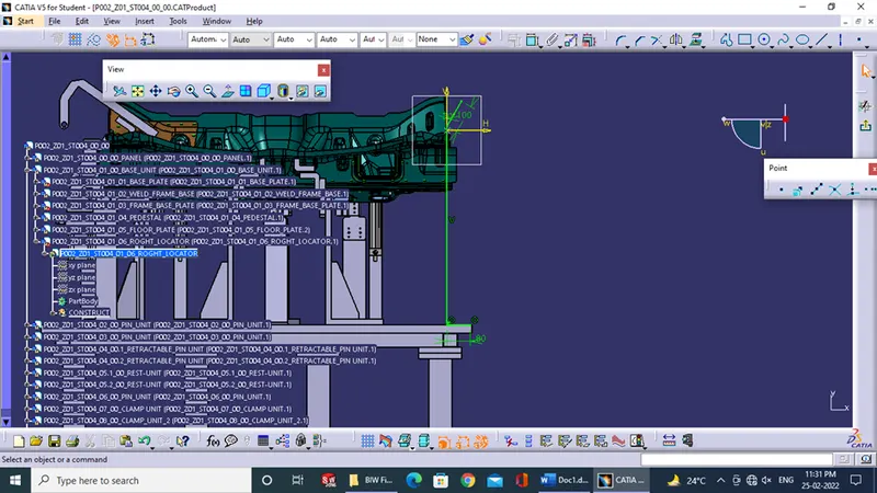
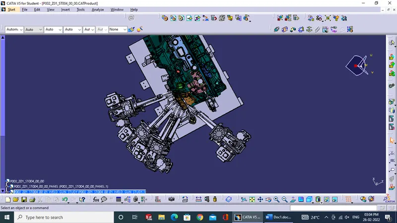
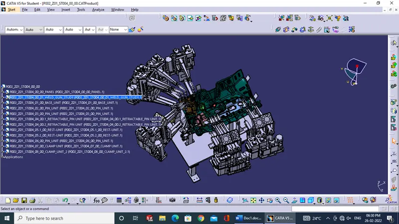
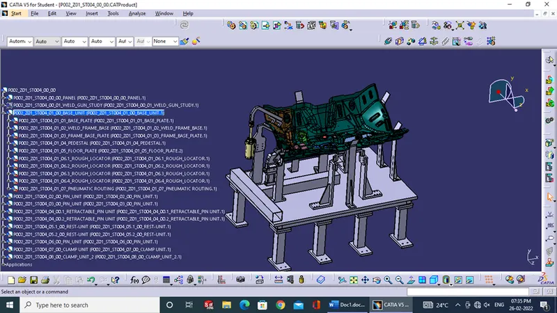
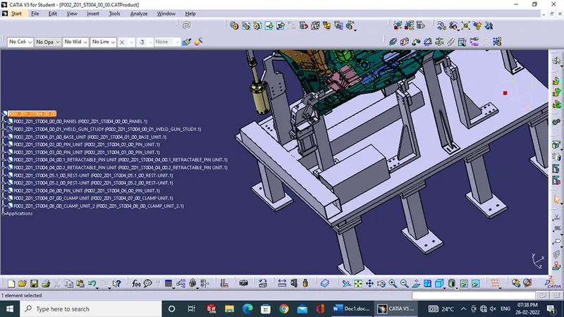
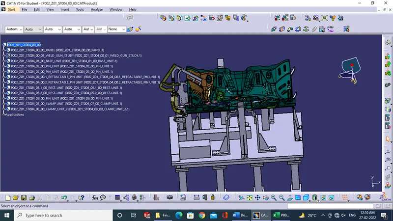
4.) A gun study for the concept made for the BIW fixture was done such that there is no clash between the components and the weld gun.
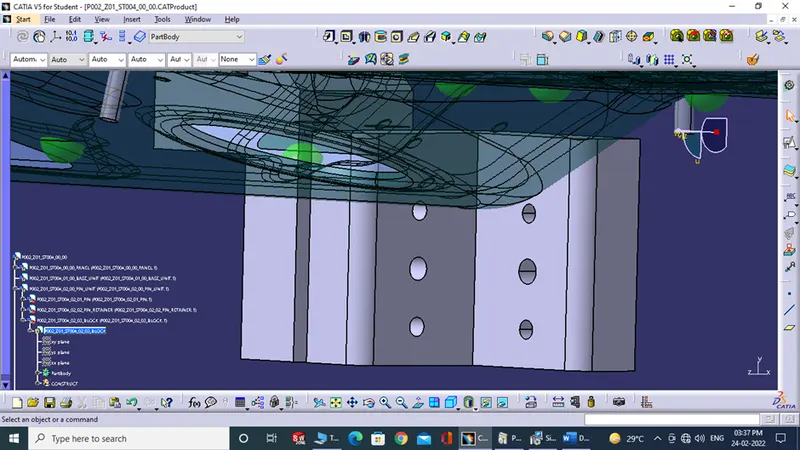
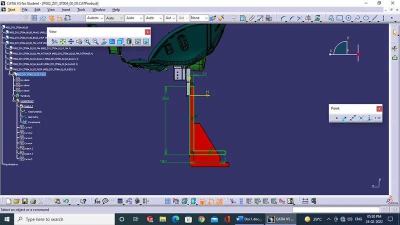
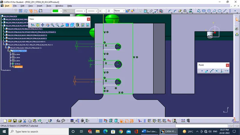
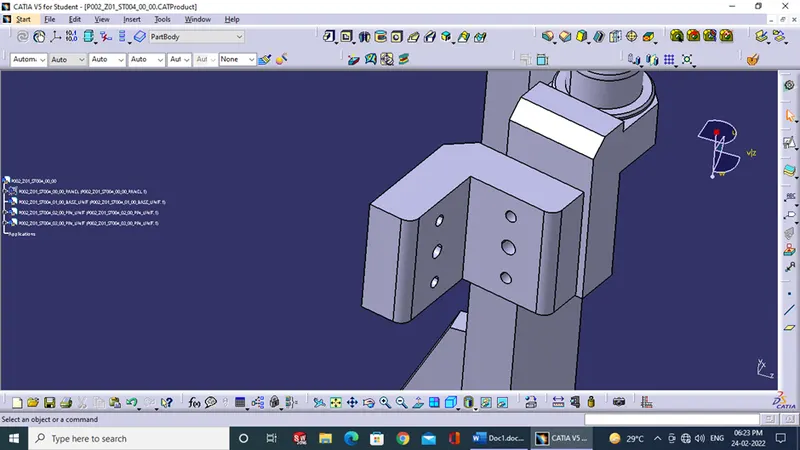
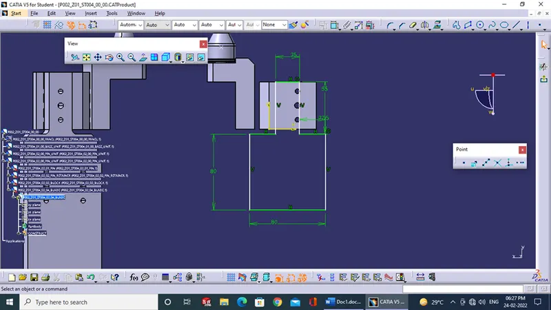
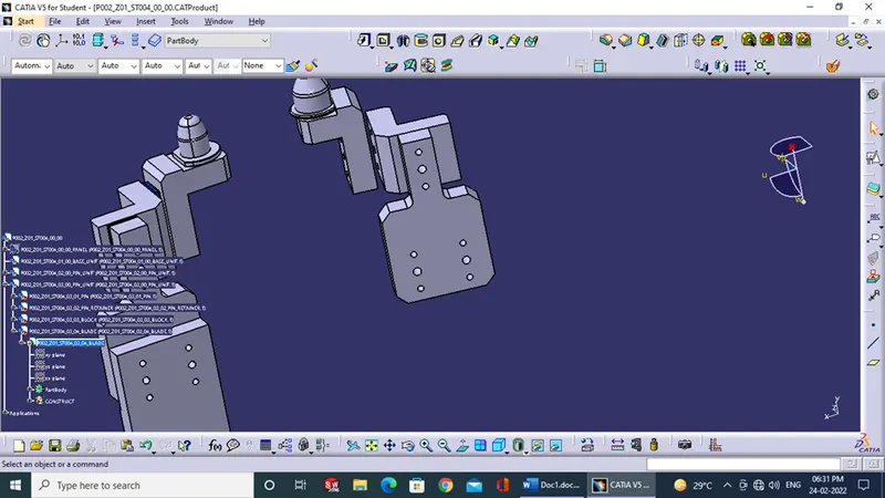
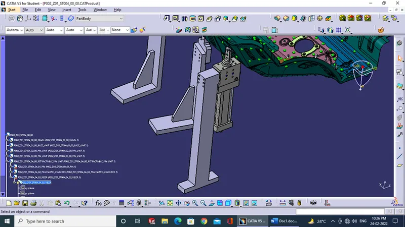
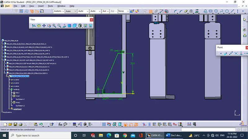
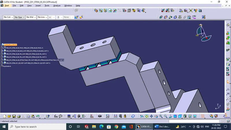
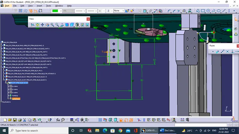
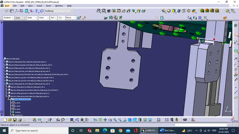
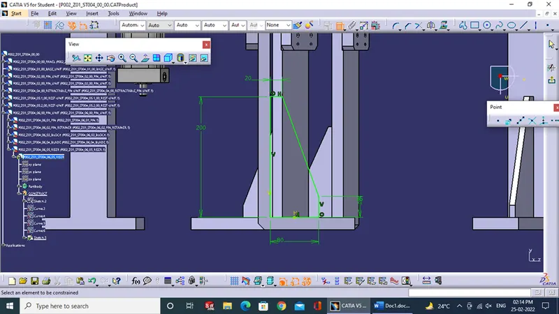
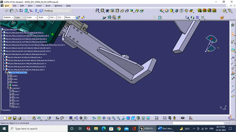
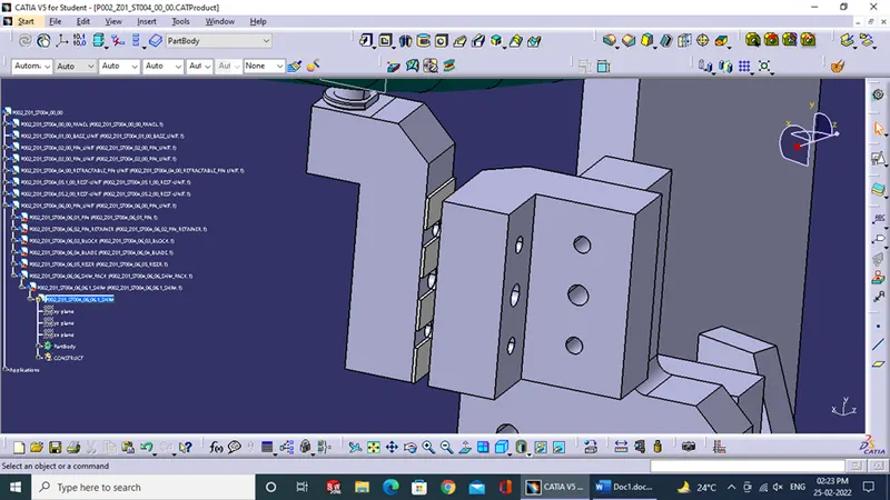
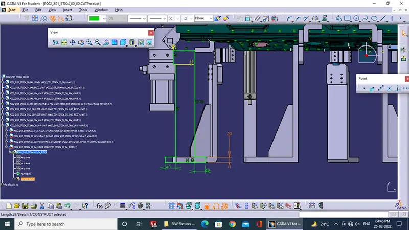
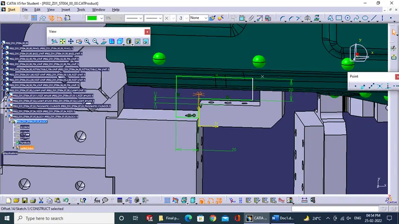
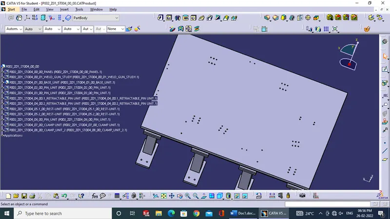
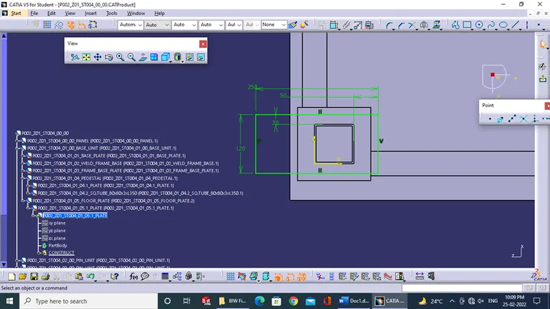
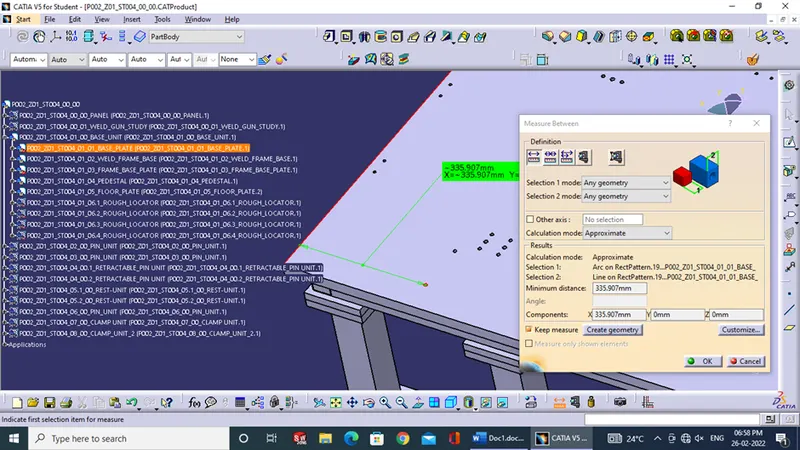
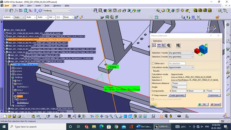
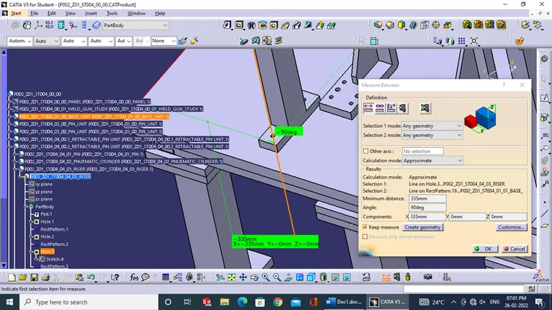
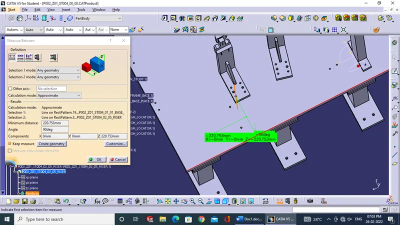
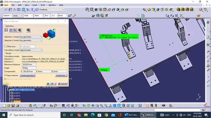
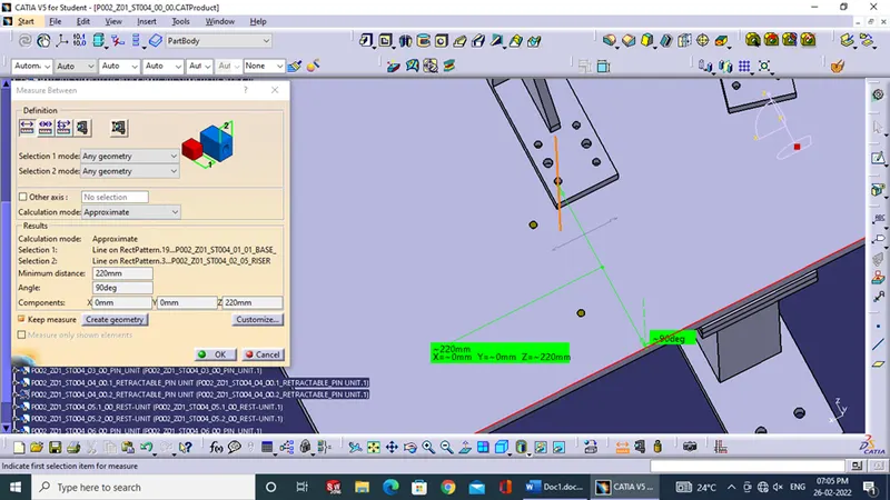
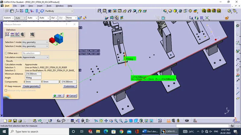
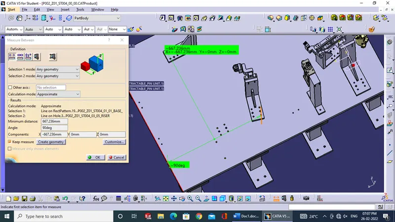
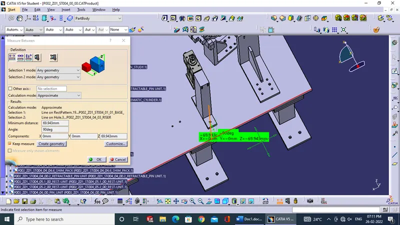
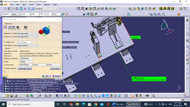
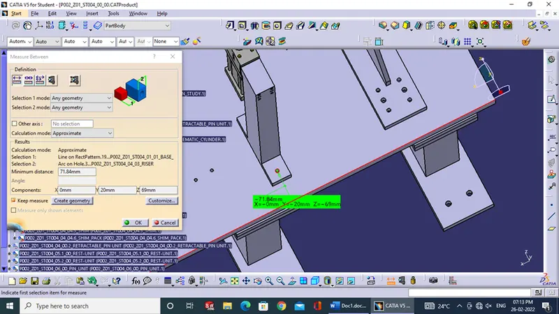
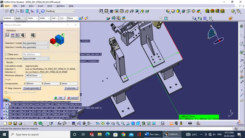
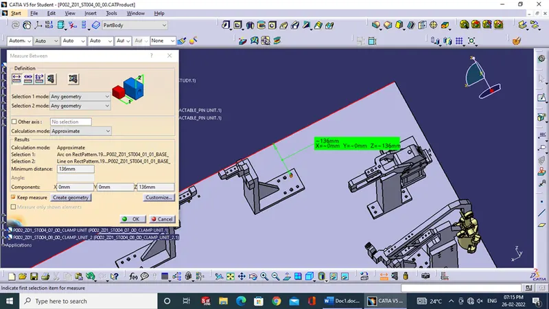
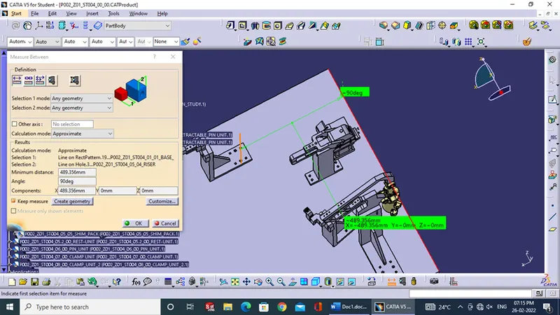
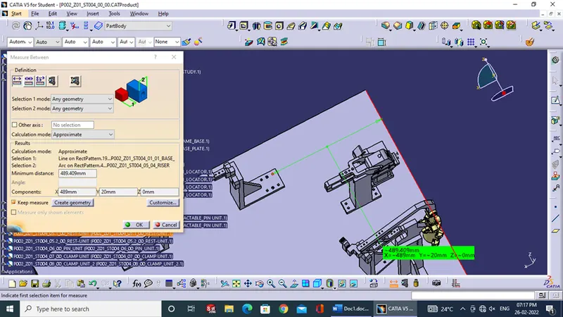
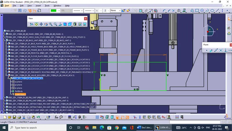
5.) When the gun test is passed final 3D finish was done for the same such that all holes are at nominal distances from edges of Base Plate so that it is easy for CMM to read the coordinates.
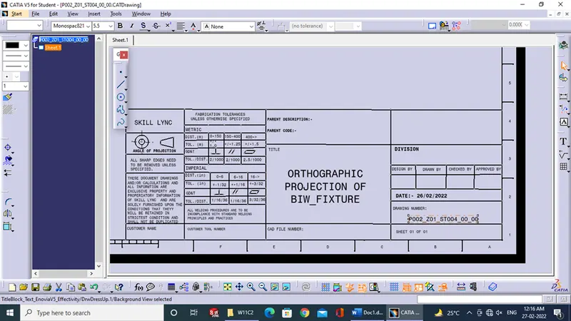
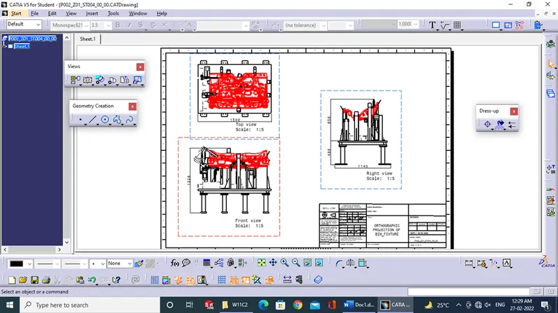
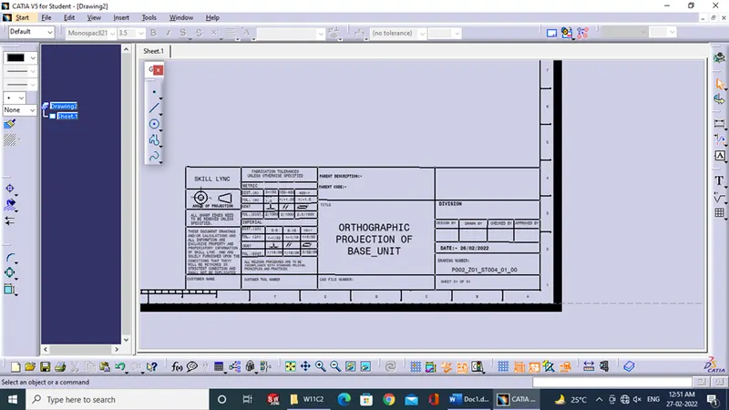
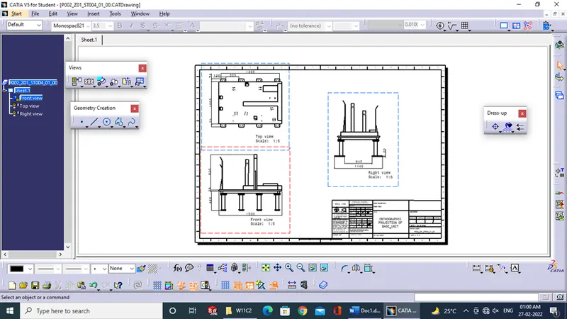
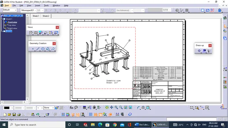
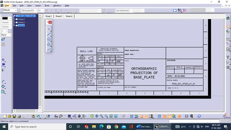
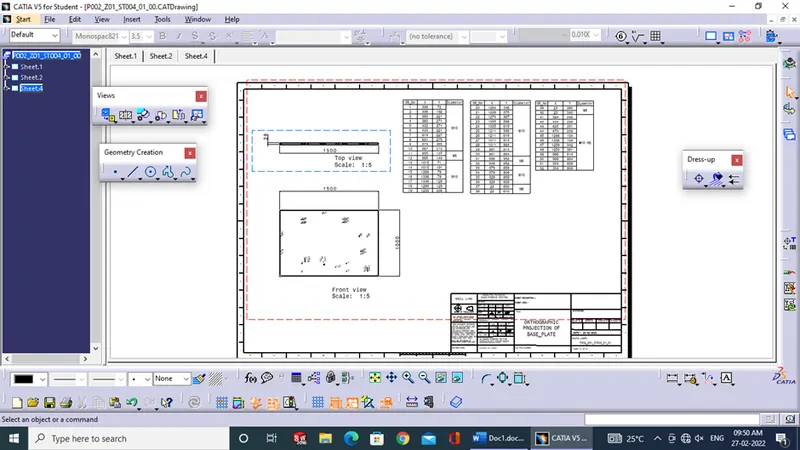
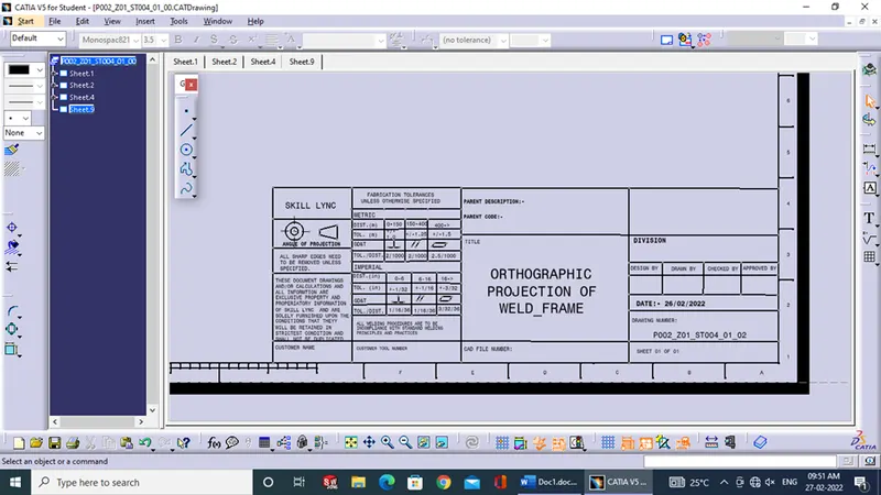
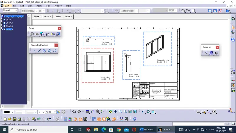
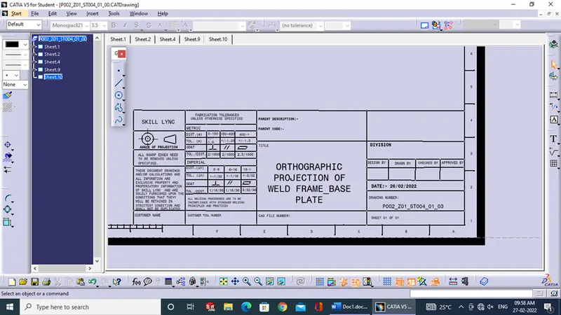
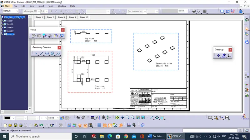
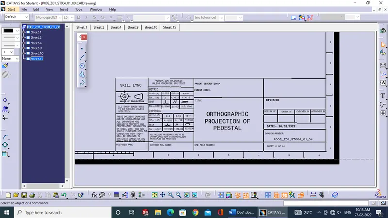
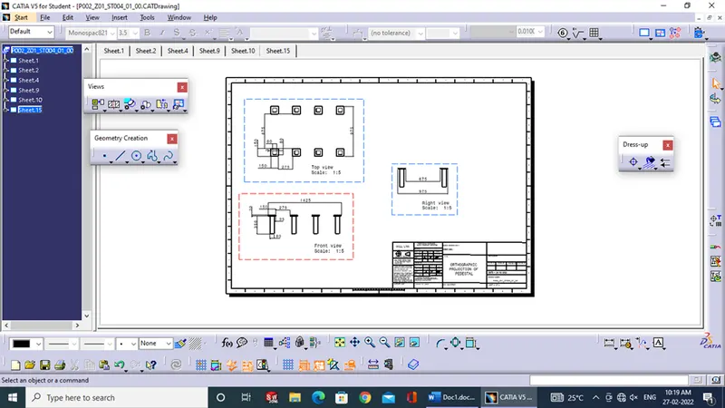
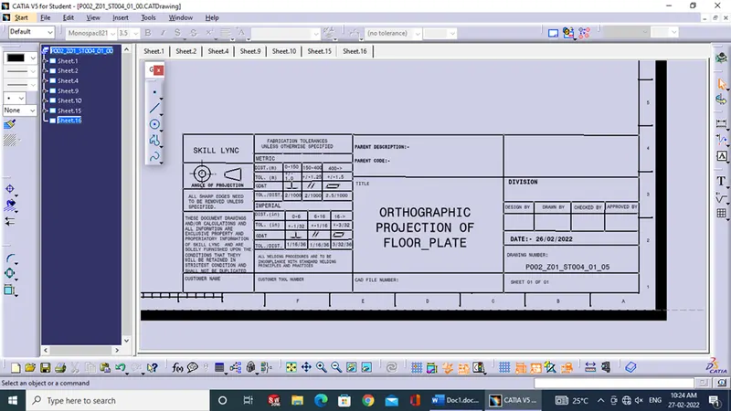
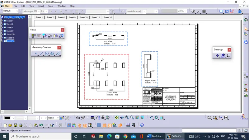
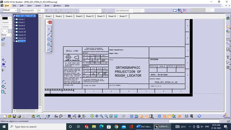
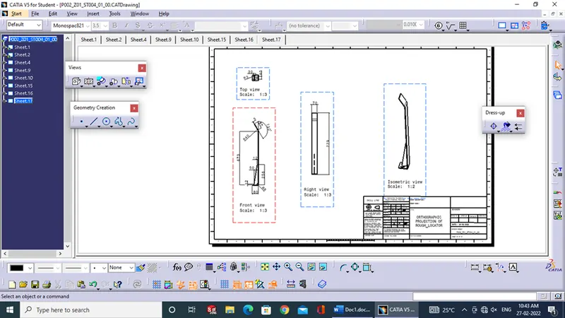
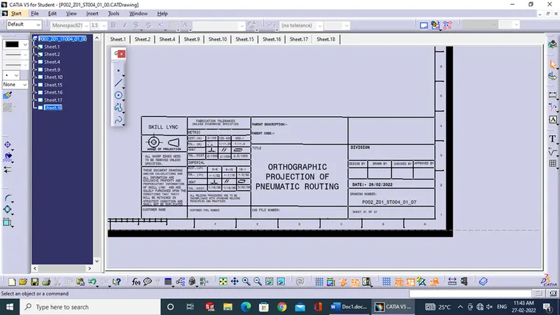
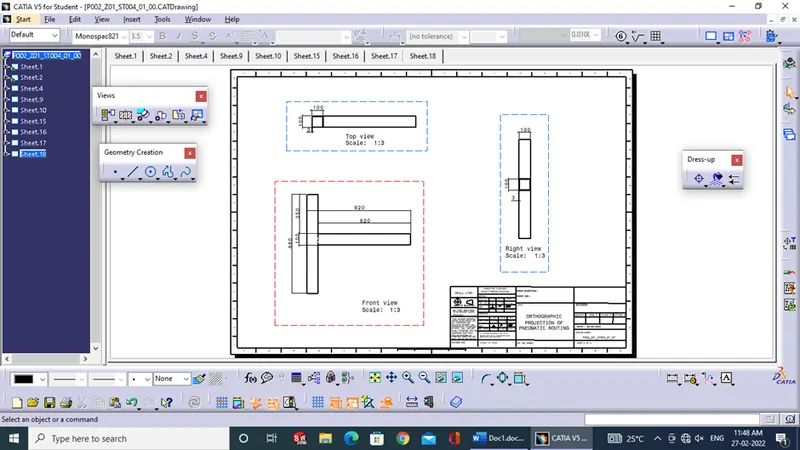
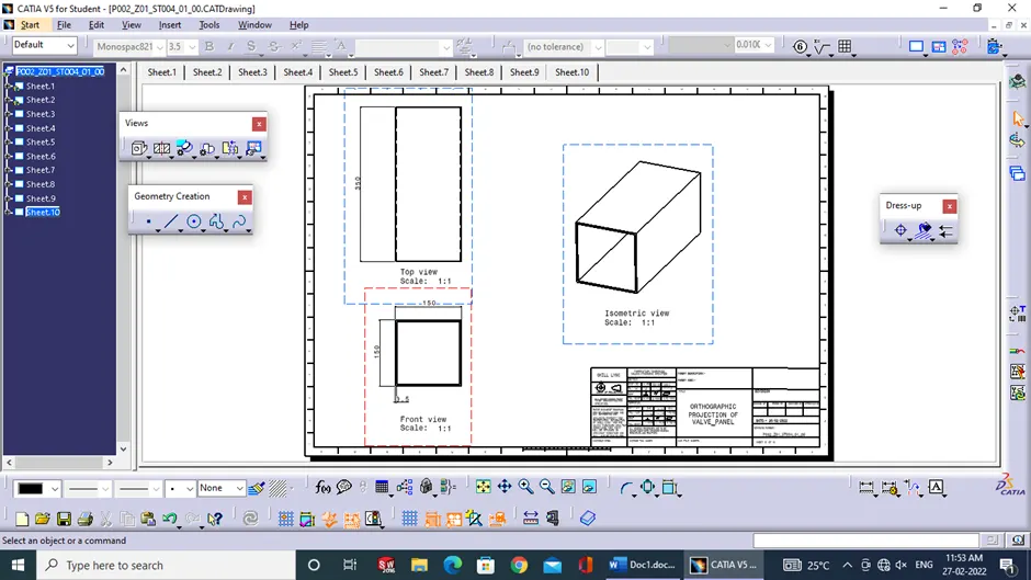
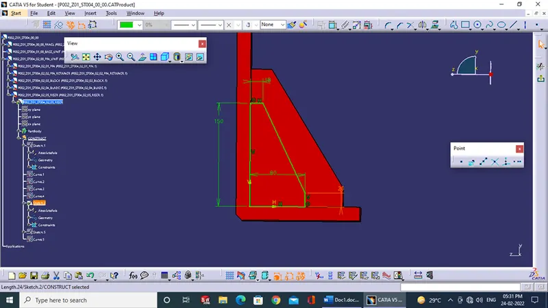
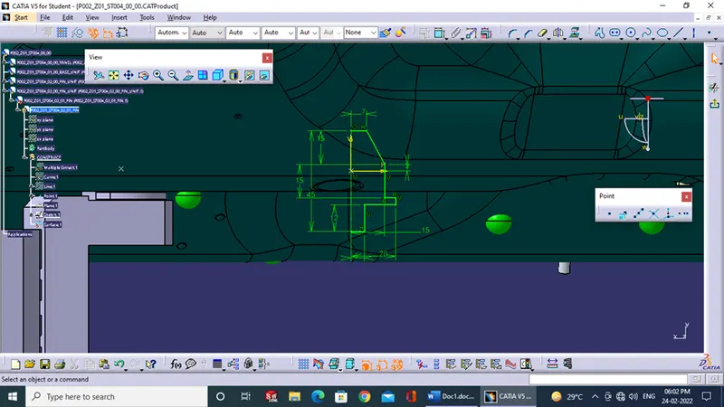
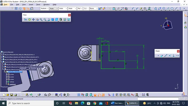
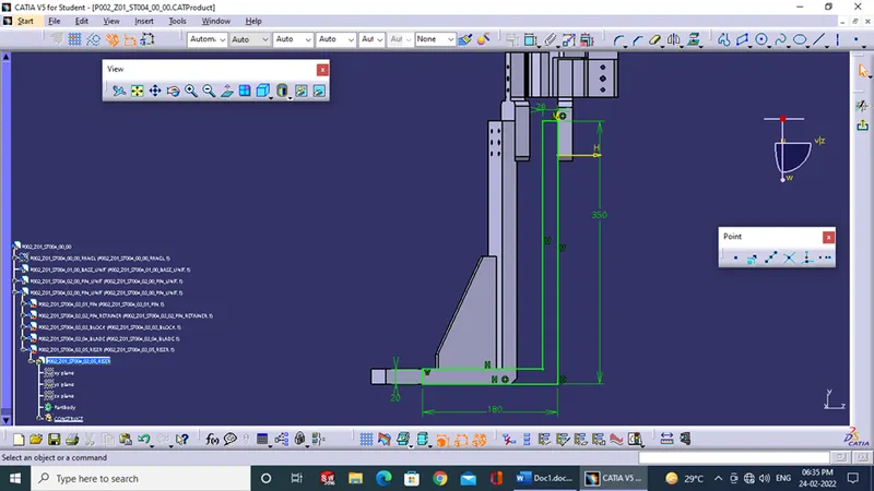
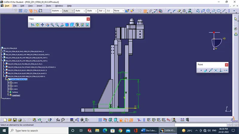
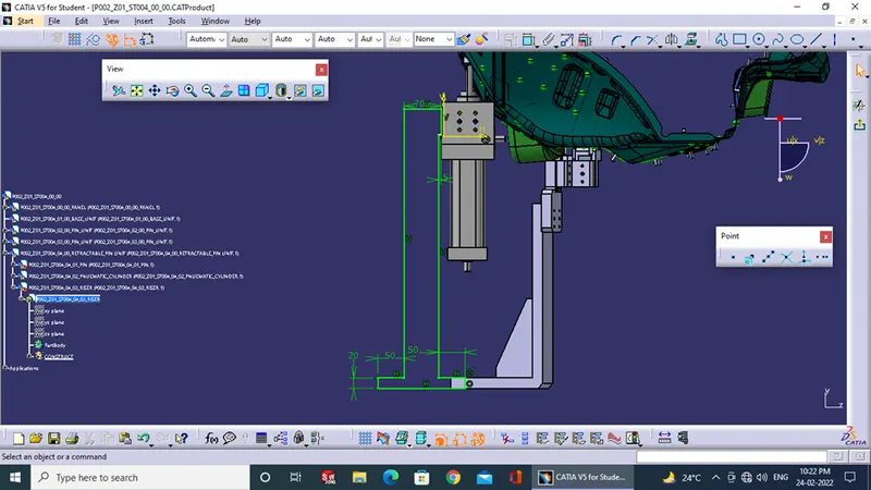
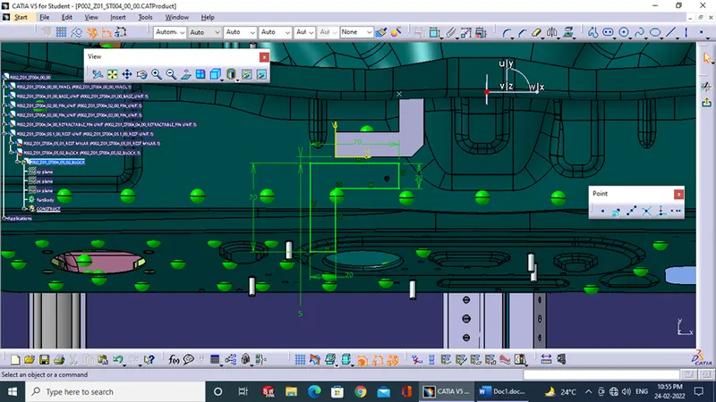
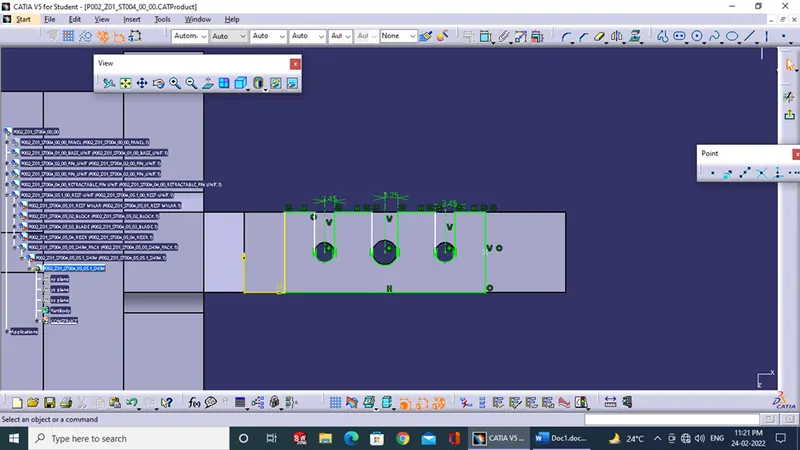
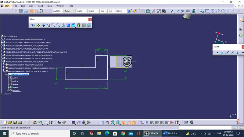
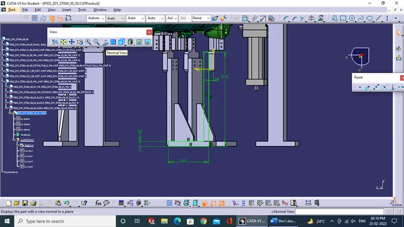
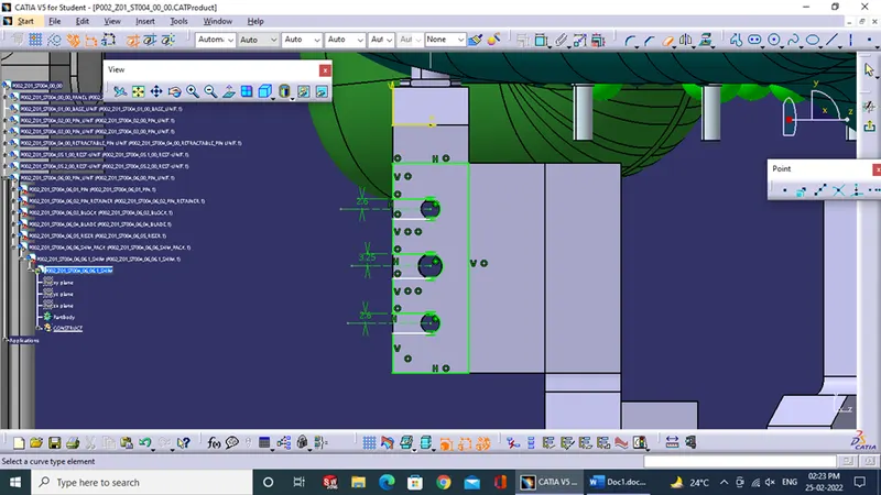
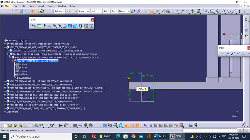
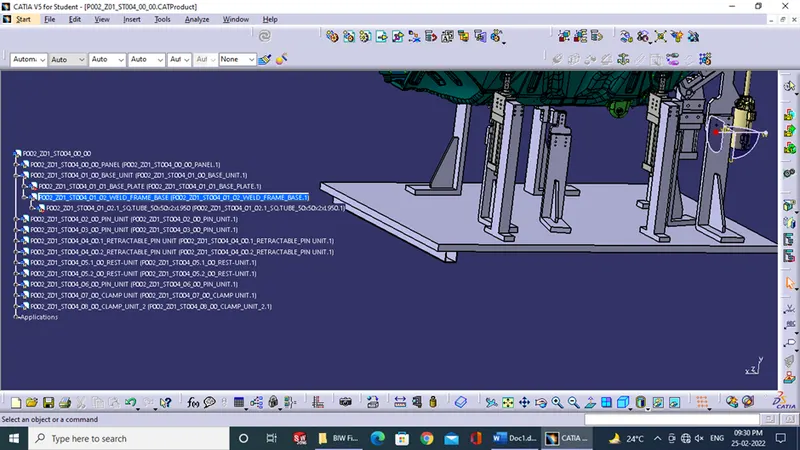
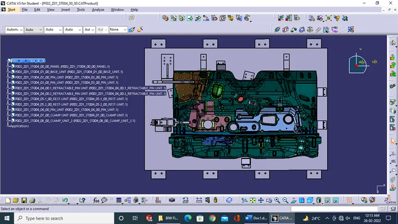
6.) Final 2D detailing is done for each unit and every part excluding the bought-out parts.
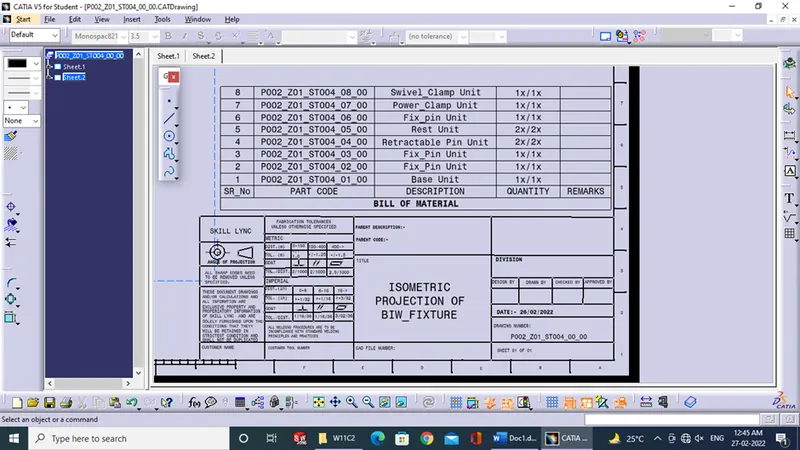
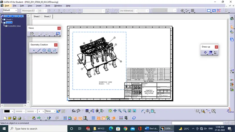
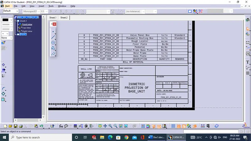
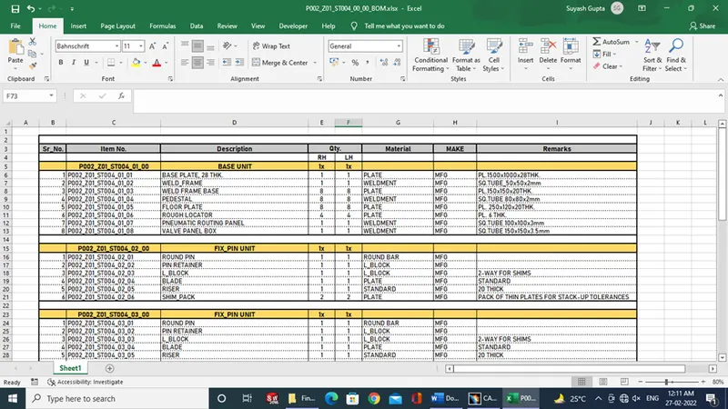
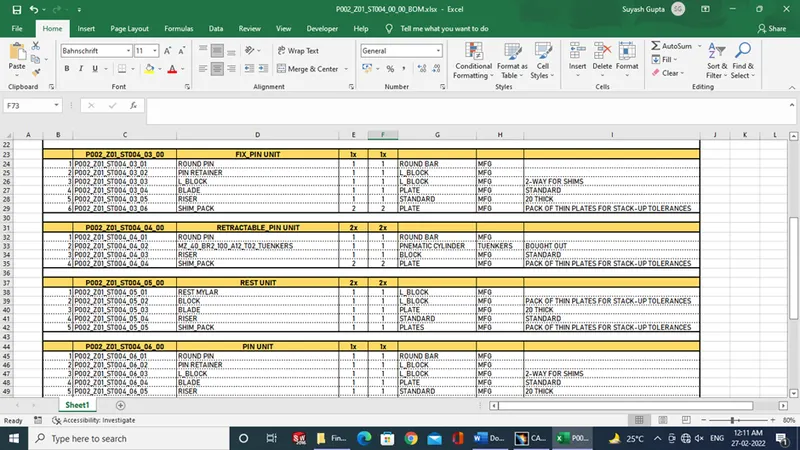
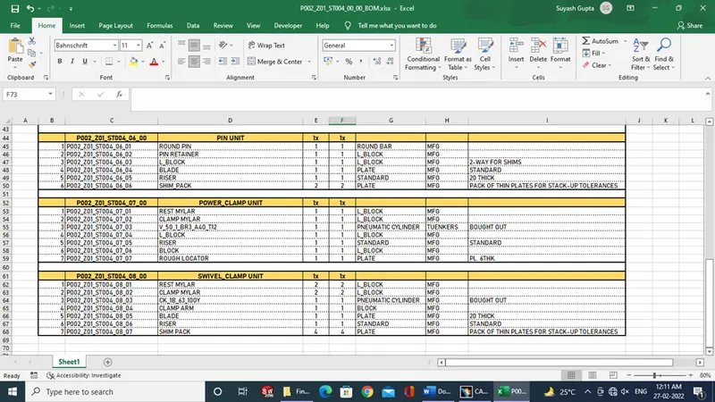
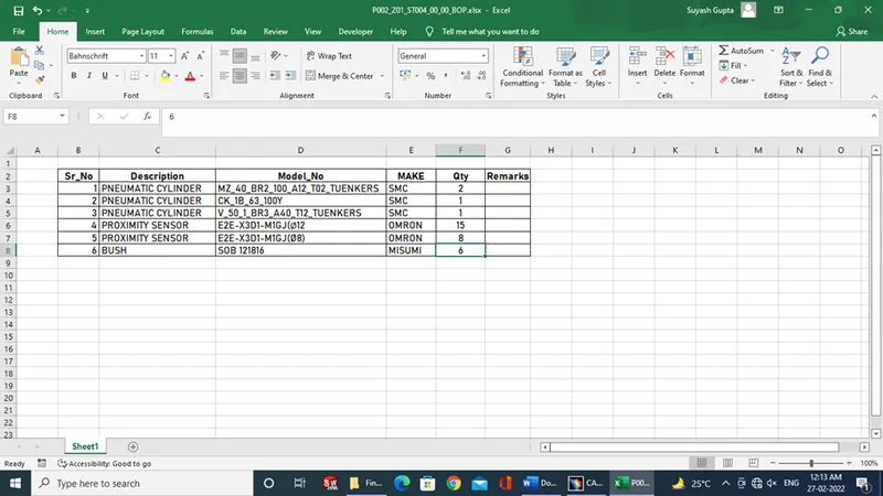
7.) Finally a BOM and BOP for the fixture are made and shared with the manufacturers.
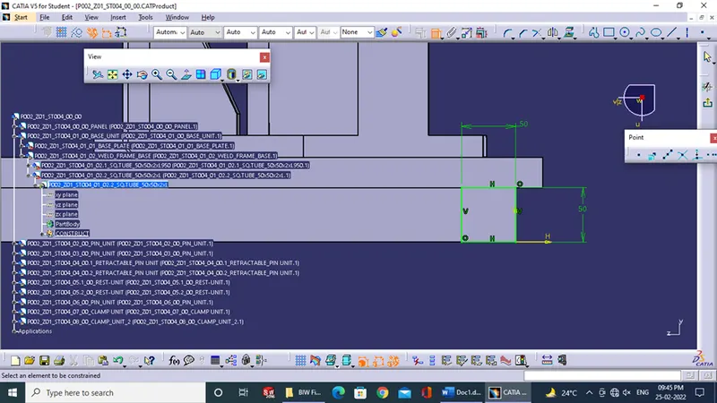
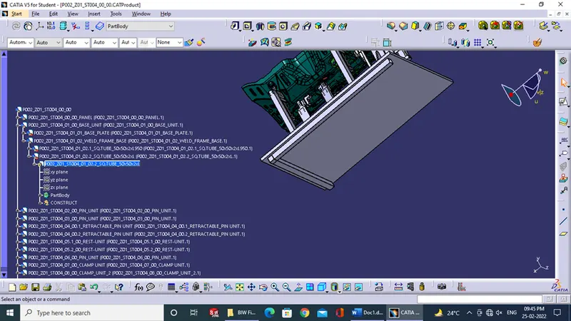
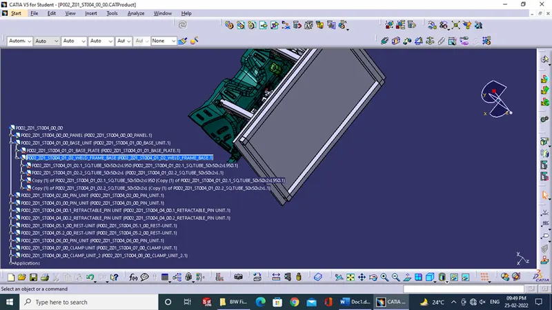
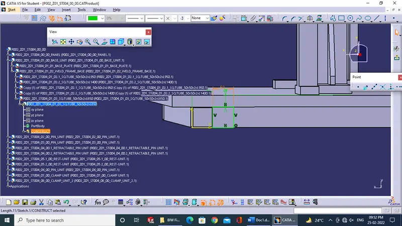
Following are images for the above report:
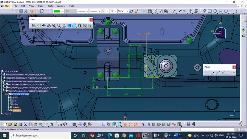
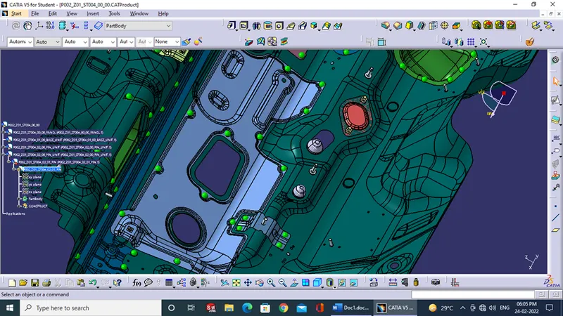
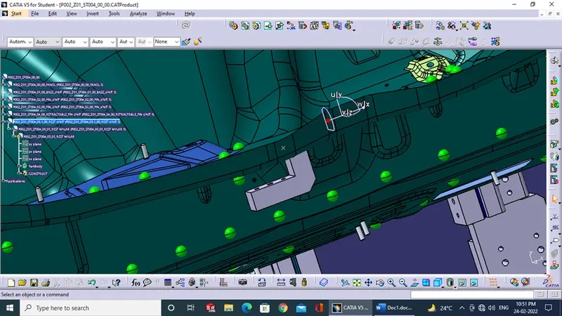
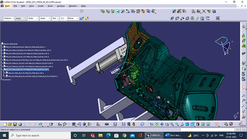
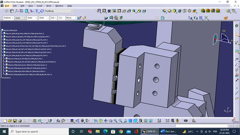
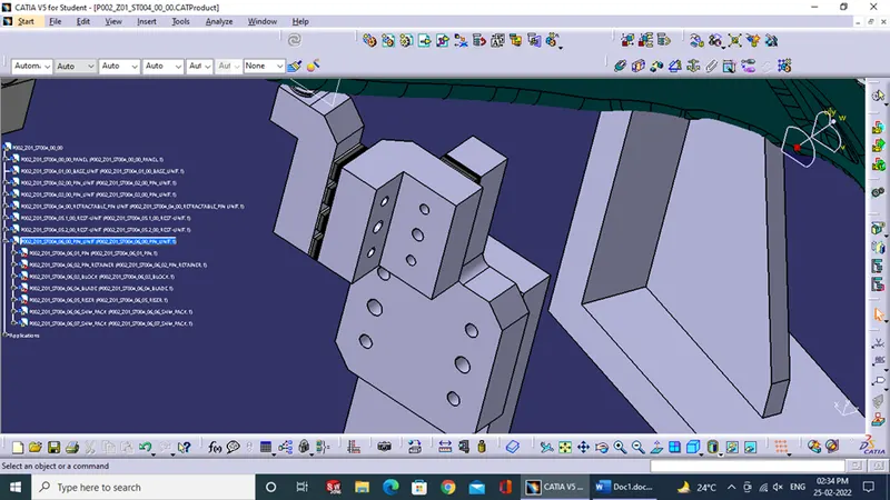
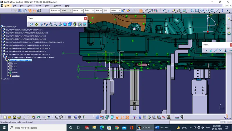
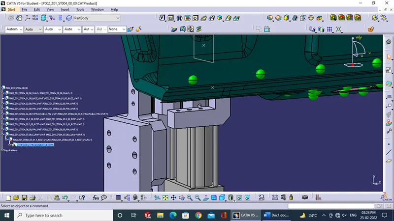
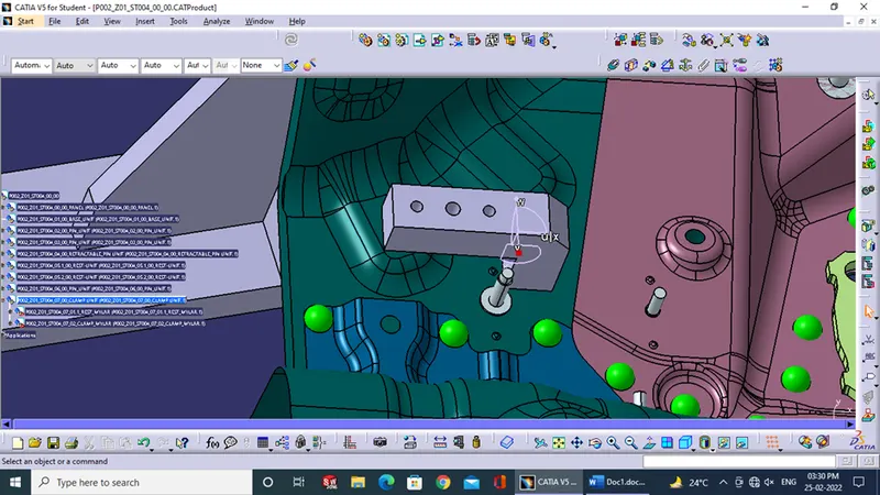
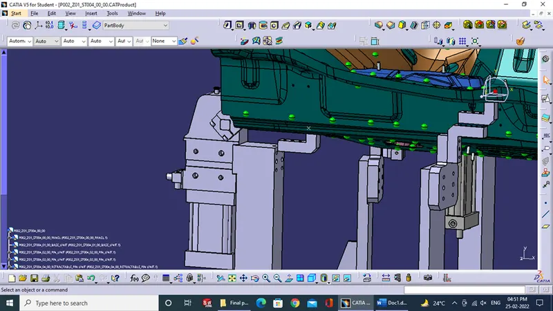
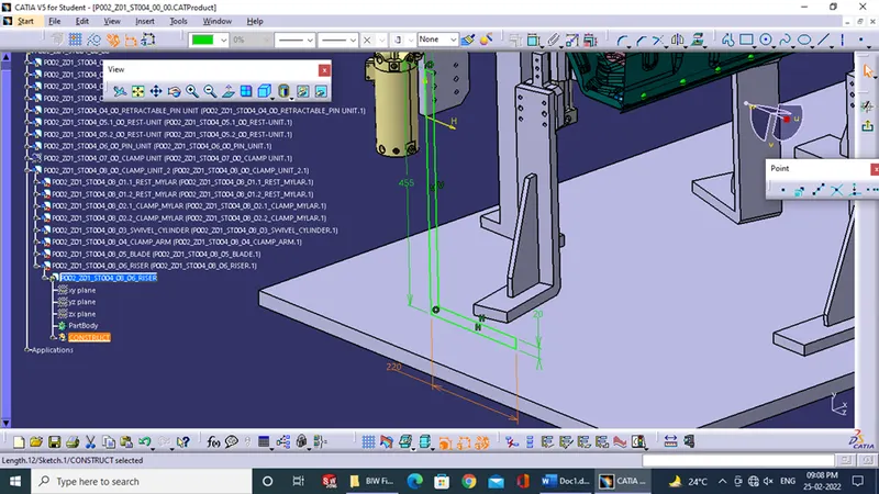
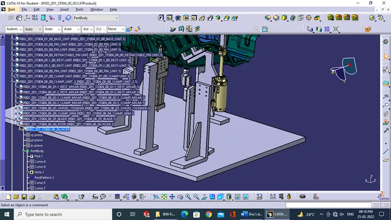
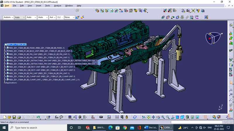
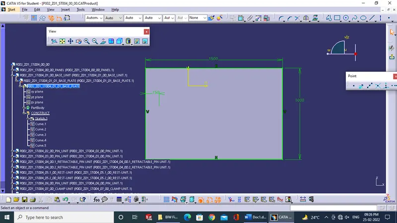
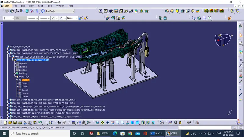
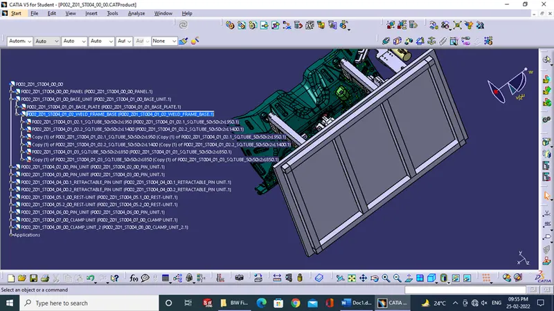
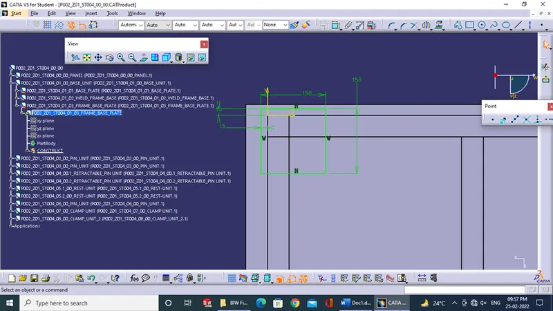
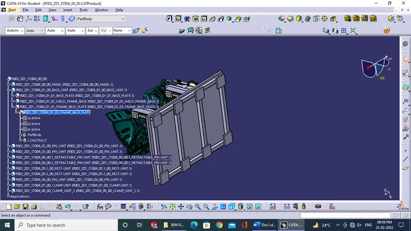
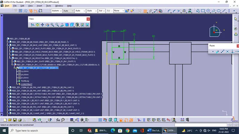
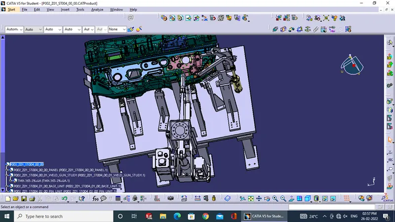
Gun Study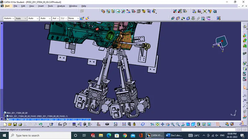
3d finish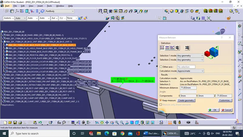
2d