Project 2
Aim
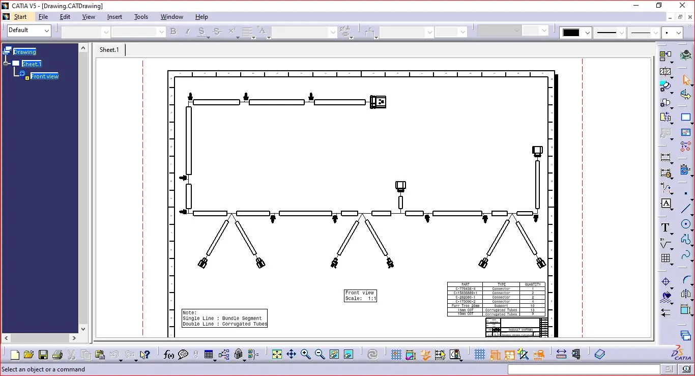
To Route the Wiring harness on given Tail Gate and Prepare flatten view drawing in CATIA V5.
Tail Gate Wiring Harness
The car back door wiring harness, as previously mentioned, specifically refers to the wiring system that runs through the rear door of a car. It is responsible for providing electrical connections between the car's main electrical system and the components located in the rear door, such as speakers, power windows, central locking system, rear defogger, and other features.
The wiring harness in the car's back door is designed to withstand the constant movement and flexing that occurs when the door is opened and closed. It typically consists of a bundle of wires encased in a protective sleeve, such as rubber or plastic, to prevent damage and ensure insulation.
Procedure
Step 1: Collect all the required 3D components and define the Parts Electrically.
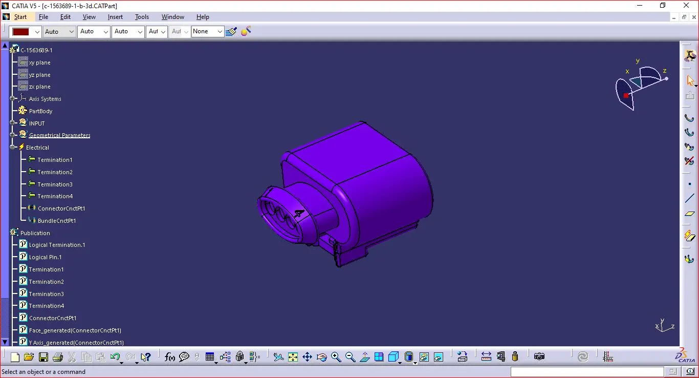
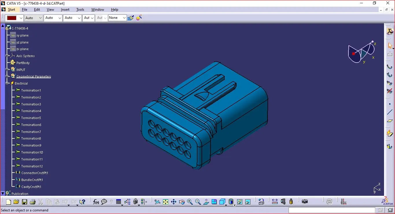
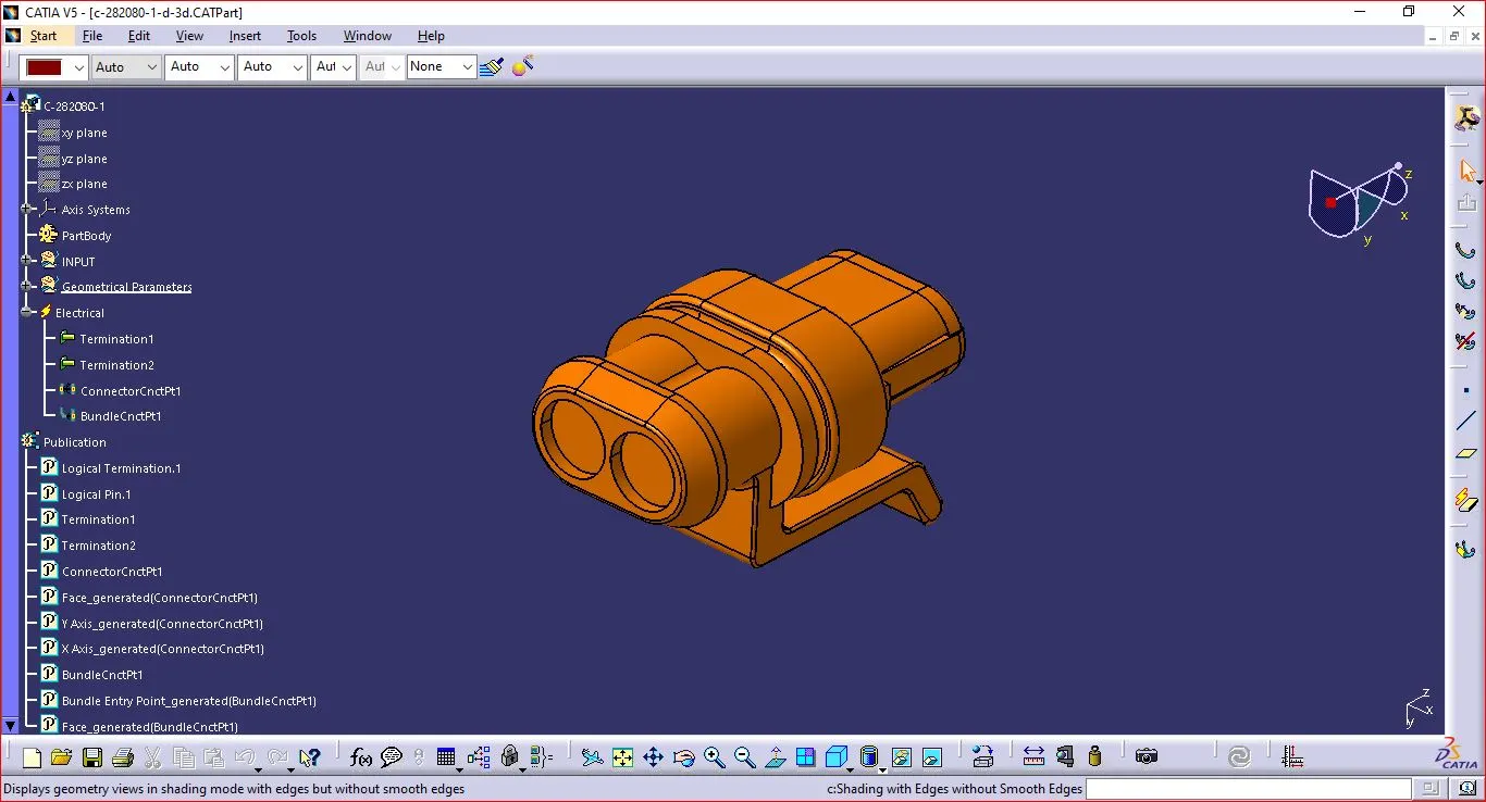
- Connectors
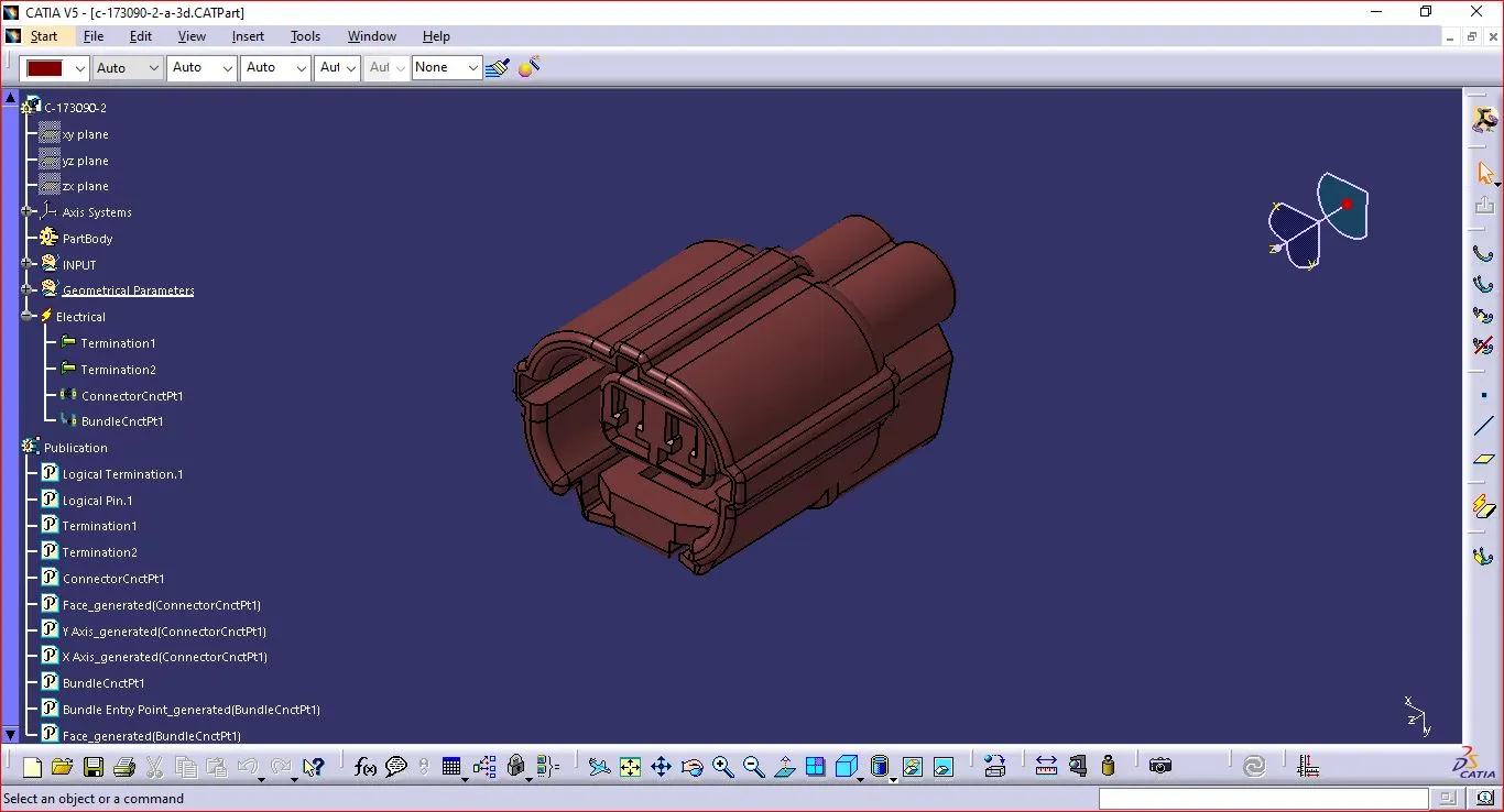
- Creation of connector connection point.
- Make a midpoint on the contact face for wire bundle insertion.
- Create an axis system referencing the newly generated point and specifying the axis direction.
- The Y-Axis should be oriented towards the connector's front face.
- The X-Axis should be oriented towards the clip's locking mechanism.
- The Z-axis should be pointing across the connector from left to right.
- Creation of Bundle Connection Point.
- Define the part as a connector and specify terminations.
- Define Bundle connection point.
- Define connector connection point.
- Define Cavity connection Point Optional.
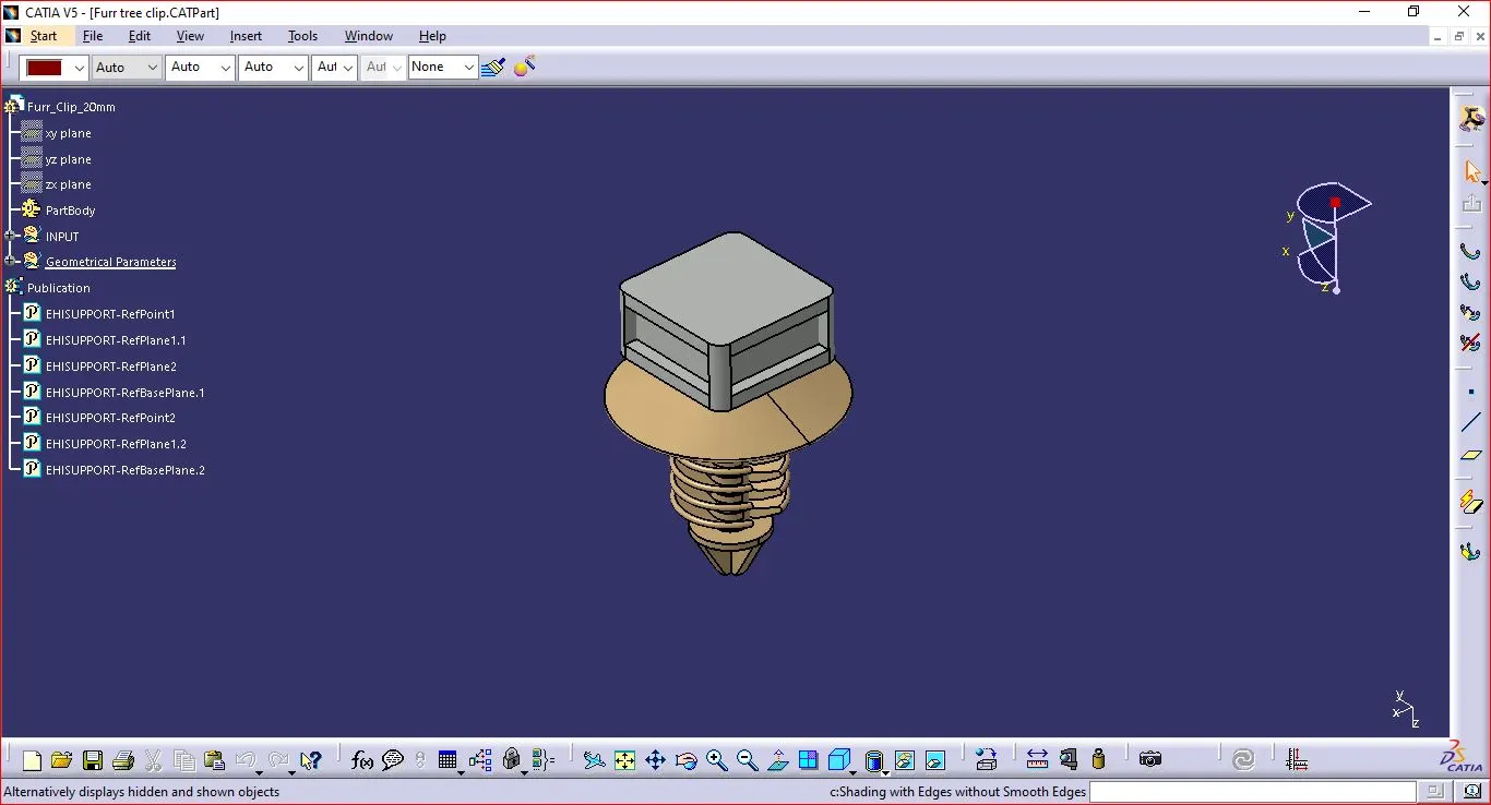
- Clips
- Add two points. Both as points of entry and exit.
- Create two planes, plus one at the base.
- Change the part design to electric
- Click on support definition, then part selection, entry point selection, entry plane selection, and base plane selection.
- Again click on support definition, and then select part, select exit point, and select exit plane, with the base plane being automatically taken as the secondary plane.
Step 2: Location of all components.
- Adding connectors to the required position.
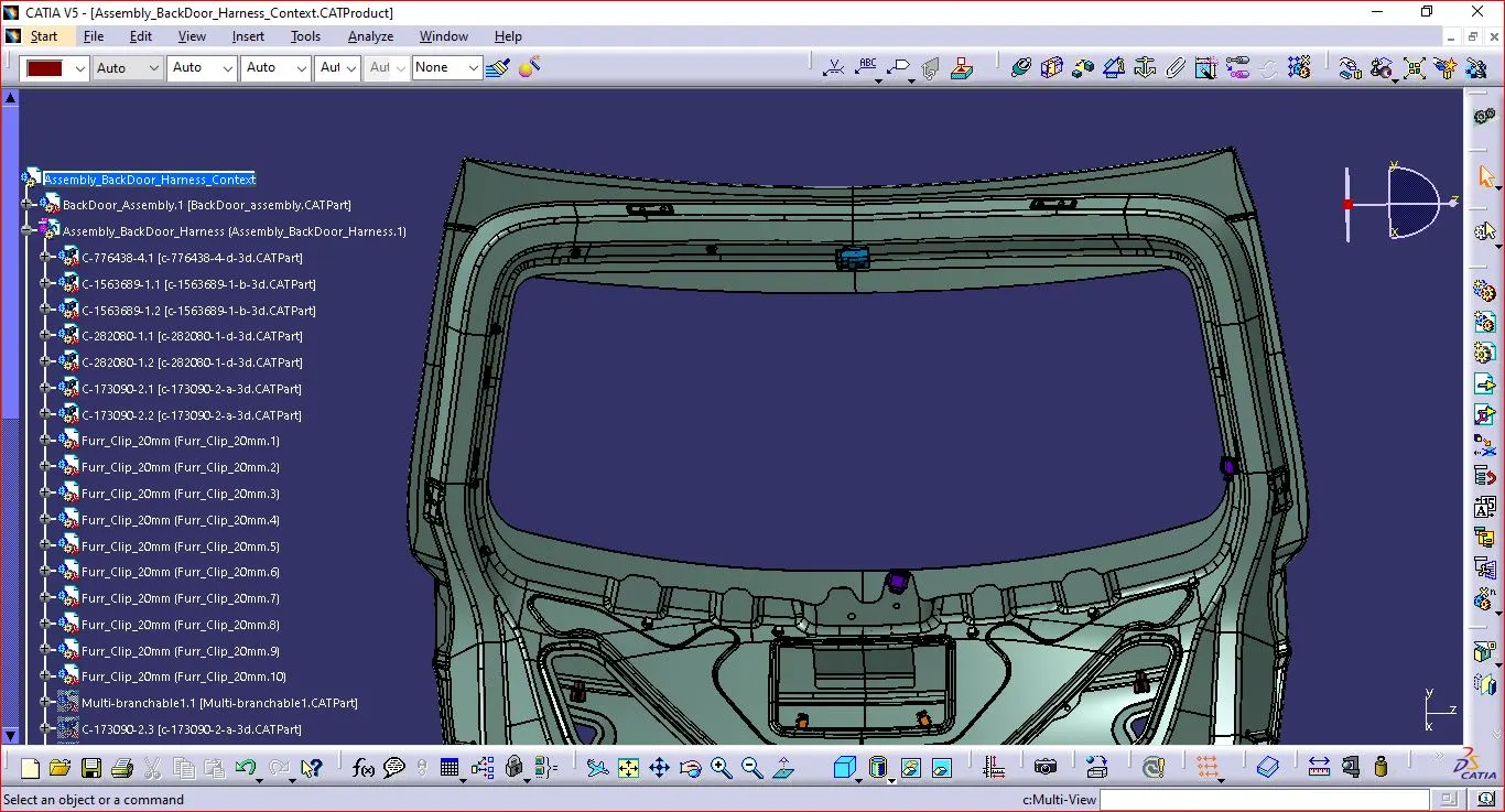
Adding Furr tree Clip to the Required Position.
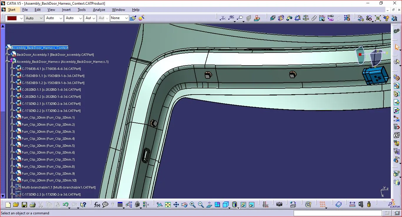
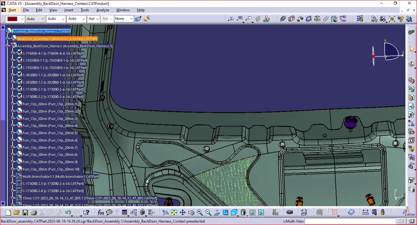
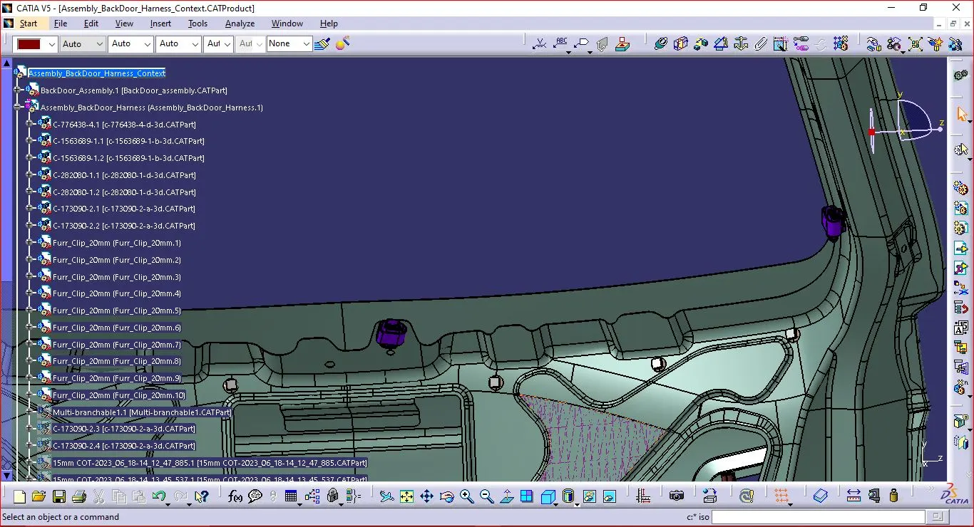
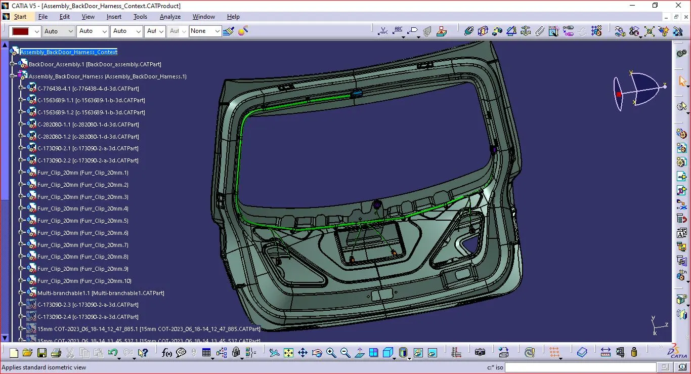
Step 3: Harness Routing.
- Define Product File as Geometrical Bundle.
- Rout the Electrically defined components with Multi-Branching.
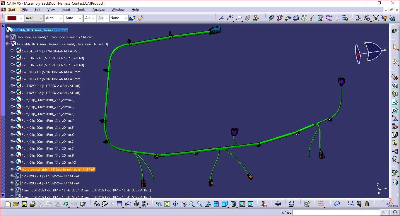
Step 4: Checking the Bundle continuity.
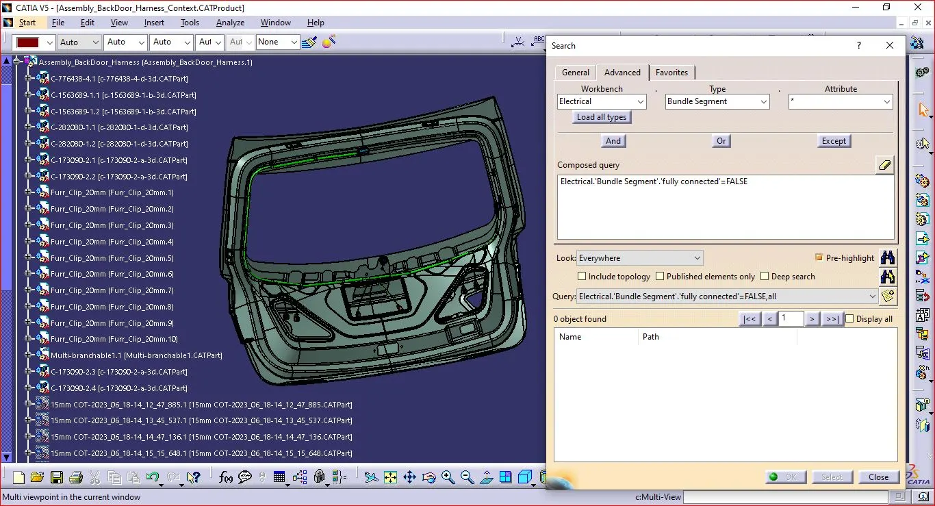
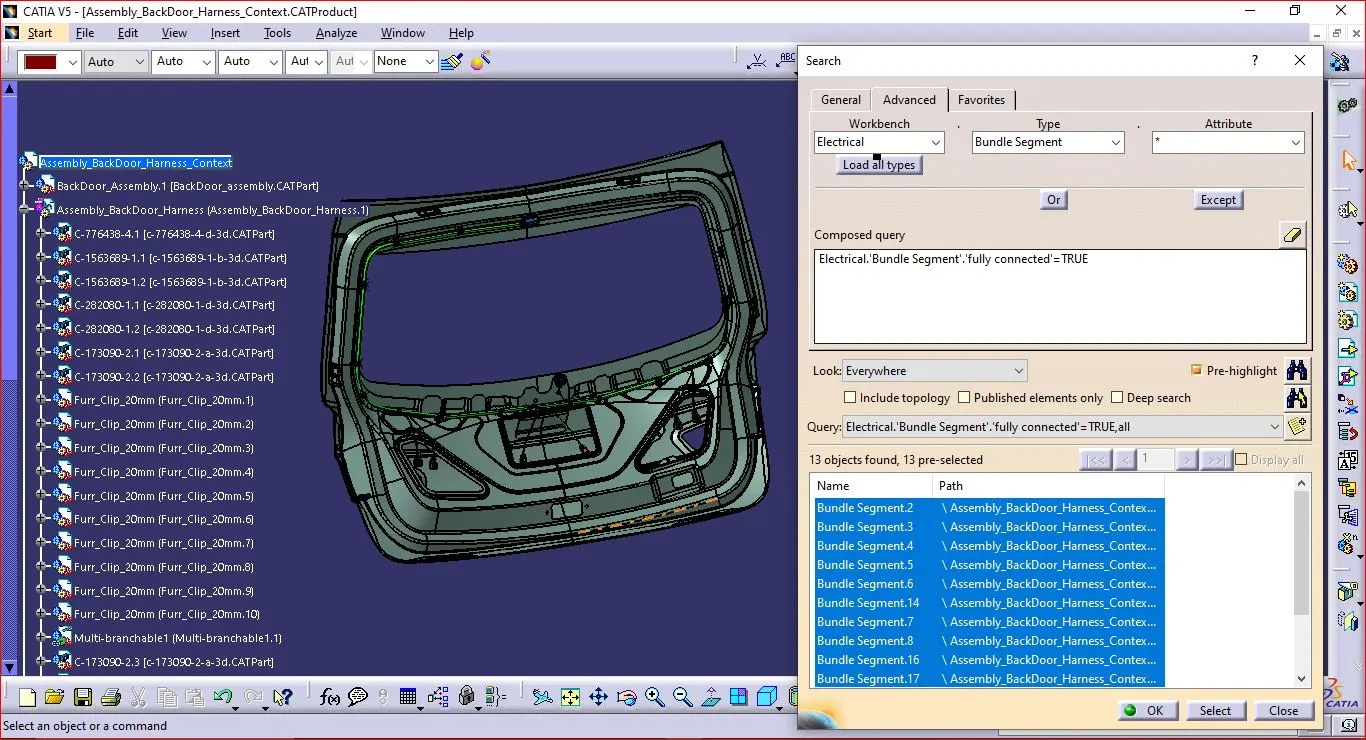
- Make sure multi-branchable is first chosen, then proceed to Edit > Search > Advanced > Workbench > Electrical > Type > Bundle Segment > Attribute > Fully Connected.
- The 'True' option will display all linked bundle segments, whereas the 'False' option will display all disconnected bundle segments.
- In this case, we chose the 'True' option and ran a search.
- As illustrated in the below image, all of the bundle segments are highlighted to show that they are all electrically connected.
Step 5: Adding protective coverings.
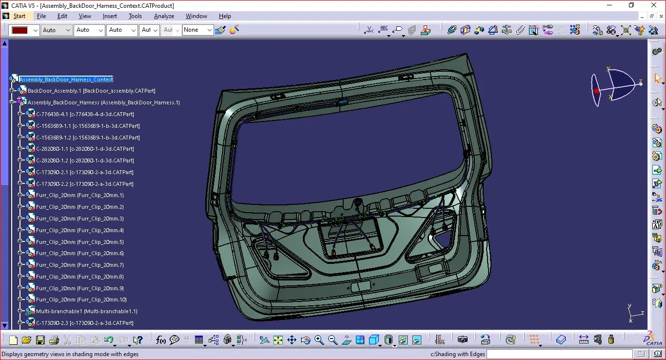
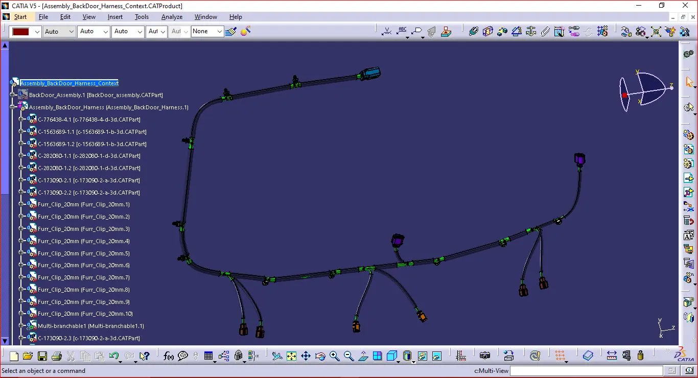
For the car tail gate, we completed the entire wiring harness layout. The top shell of the guiding channel as well as all bundle segments must now be covered with protective materials.
Step 6: Harness Flattening
- Define the "Flattening Parameters" in harness flattening Workbench.
- Extract the Harness assembly to the Harness Flattening Workbench.
- The parts are assembled in a proper way that they are easily visible.
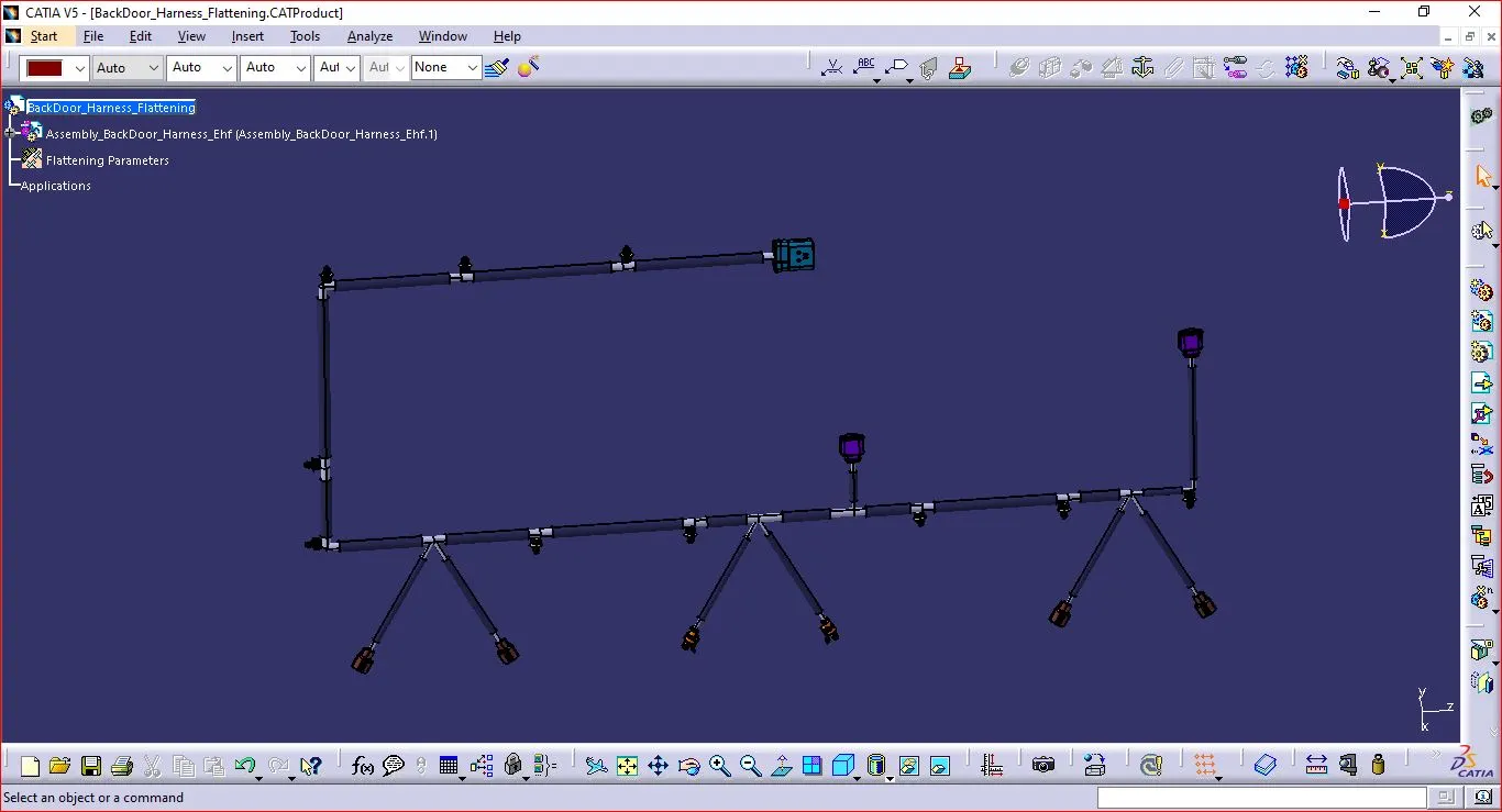
Step 7: Harness flattening Drawing
- Make a drawing file for the harness product that has been flattened.
- First, we must ensure that bundles and protective covers have distinct graphical representations in the flatten parameter settings
- Single-line illustration of bundle segments
- Coverings used as protection - Double line illustration.