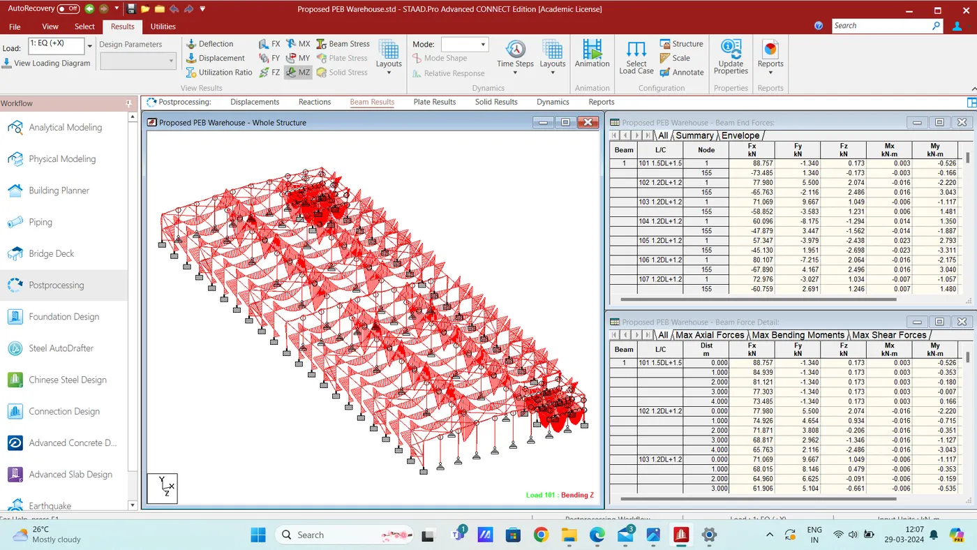
Project 2
Model & Design a Proposed PEB Warehouse using STAAD. Pro with following Technical specification.
Aim:-
To Model and Design a Proposed PEB Warehouse using STAAD Pro.
Procedure:-
Step 1:-
- Open a STAAD Pro software and Create a File.
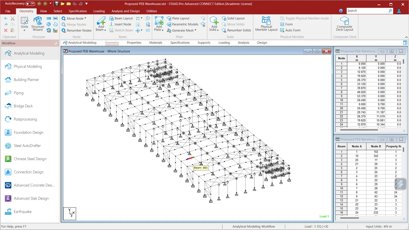
- In Geometry Tab, Create Model using Nodes and Beam commands.
Step 2:-
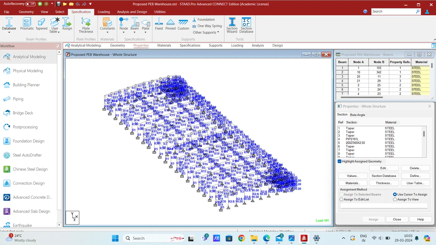
- In Specification Tab, Create and Assign a Sections for the Model.
Step 3:-
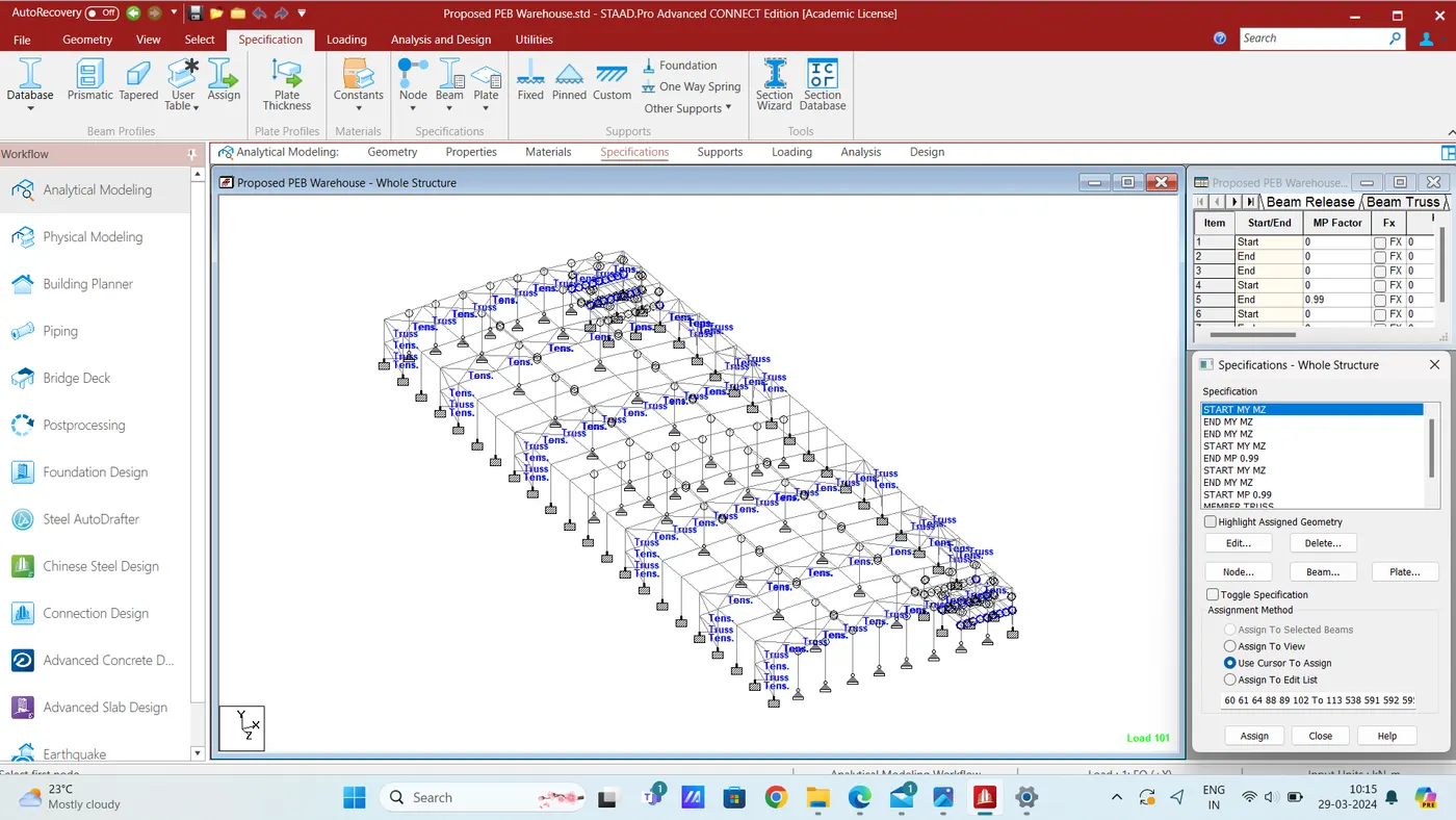
- In Specification Tab, Create a Moment Release and Assign to the Gable End Columns.
Step 4:-
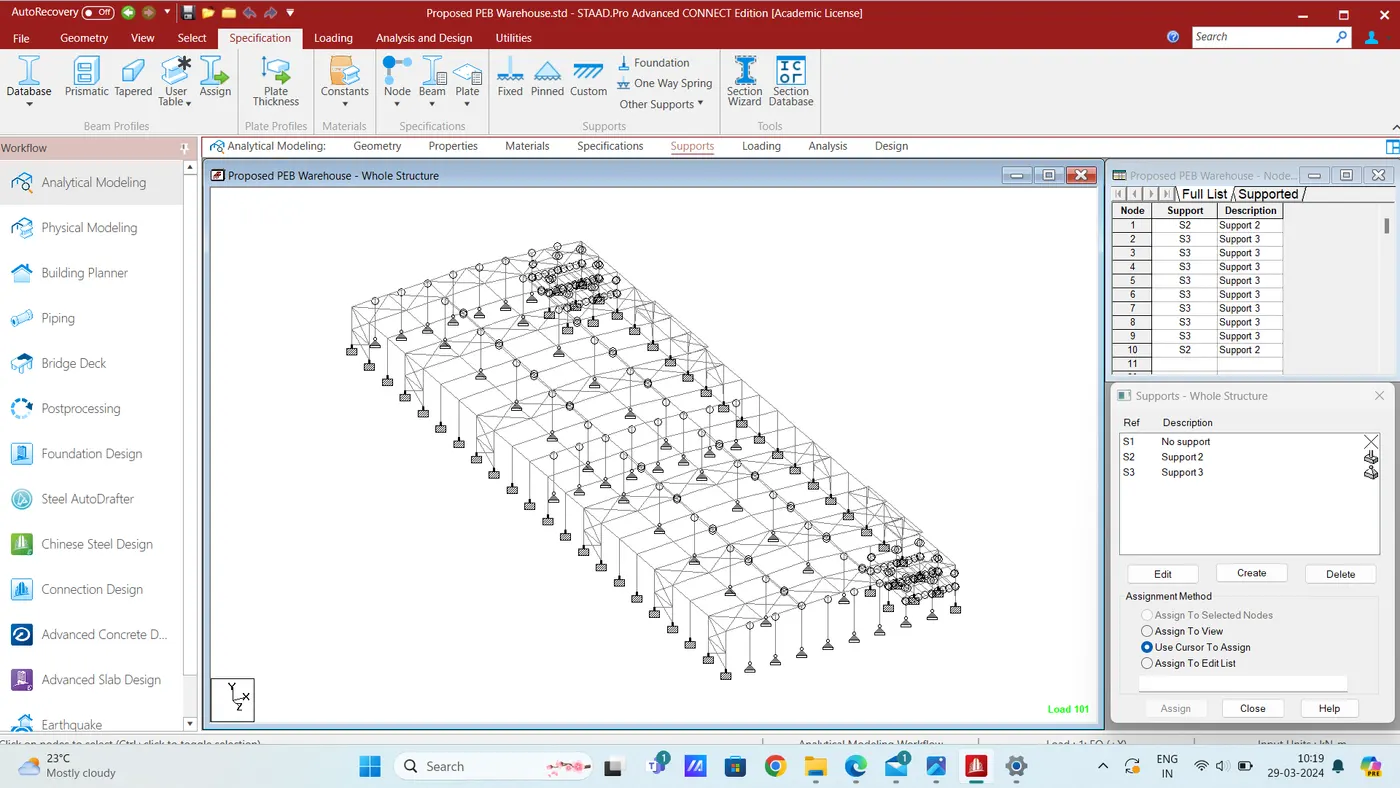
- In Support Tab, Create a Fixed Support and Assign the supports to the all Columns.
Step 5:-
Load Calculation:
Seismic Load:
Zone Factor = 0.16 (Zone III)
Response Reduction = 4 (Ordinary Moment Resisting Frames)
Importance Factor = 1.0 (Category 4)
Soil Type = 1.0 (Hard Soil – As per Staad)
Type of Structure = 3.0 (Steel Moment Resisting Frames = As per Staad)
25% of Live Load on roof shall be considered for calculation of seismic forces.
100% of collateral load on roof shall be considered for calculation of seismic forces.
50% of (Live load + Collateral load) on mezzanine floor shall be considered for calculation of seismic forces.
100% of Dead load shall be considered for calculation of seismic forces.
For seismic in longitudinal direction, diaphragm action due to purlin and sheeting can be considered. Diaphragm actions should not be used while designing bracing system for wind load.
Provisions of Chapter 12 of IS: 800 - 2007 need not be considered while designing structure.
Dead Load:
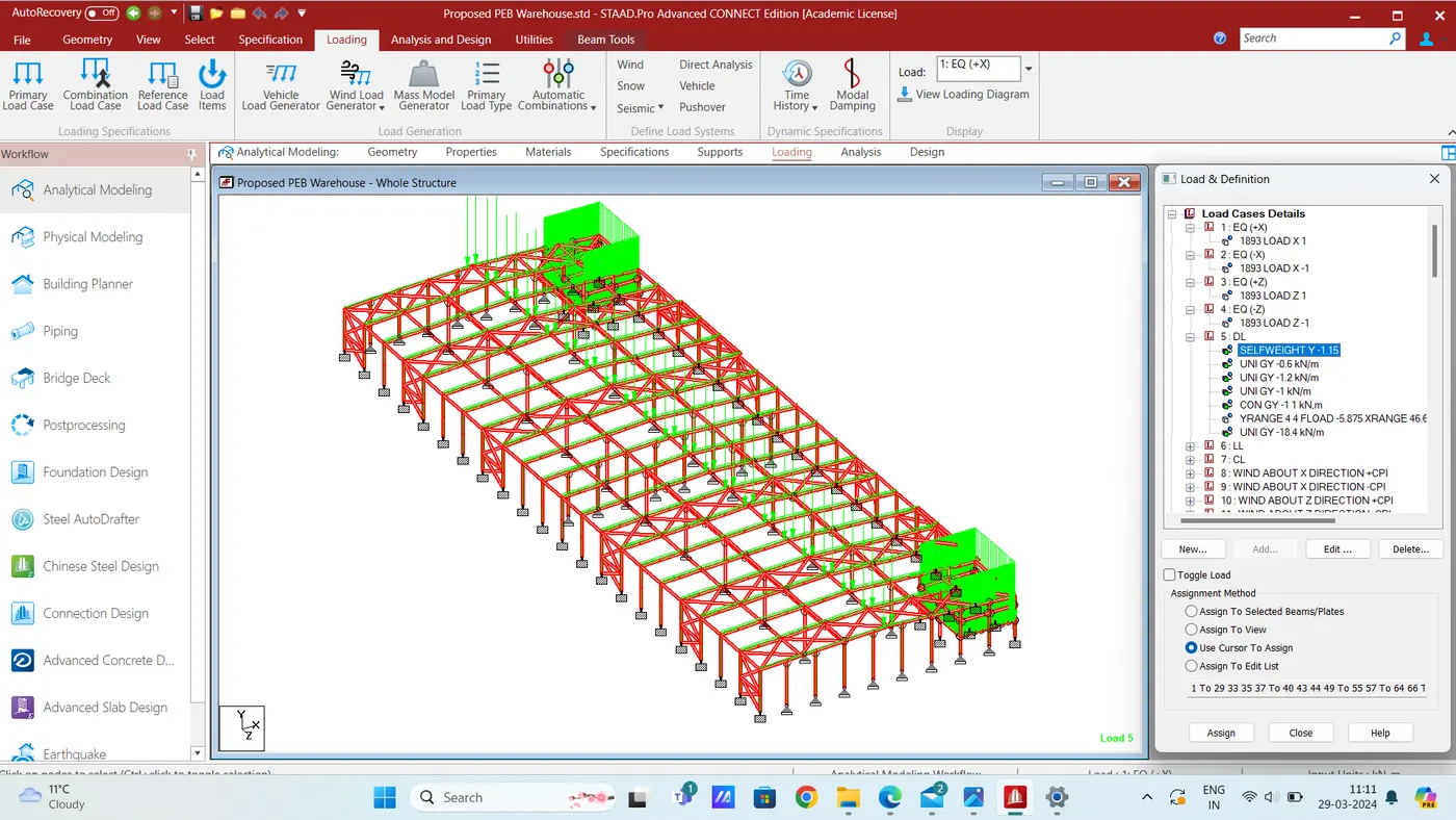
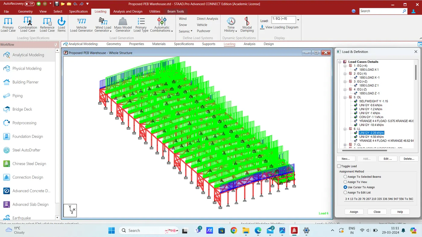
1) Self weight - Assigned to the entire structure as shown in the print screen given below-
2) Purlin - 10 Kg/m2 and 10 kg/m2 for roof sheeting are as per calculation and print screen given below-
= 20 x 6 (Bay width along span of truss) = 120 Kg/m2
= 1.2 kN/m2 on main rafter
&
0.6 kN/m2 on Gable frame
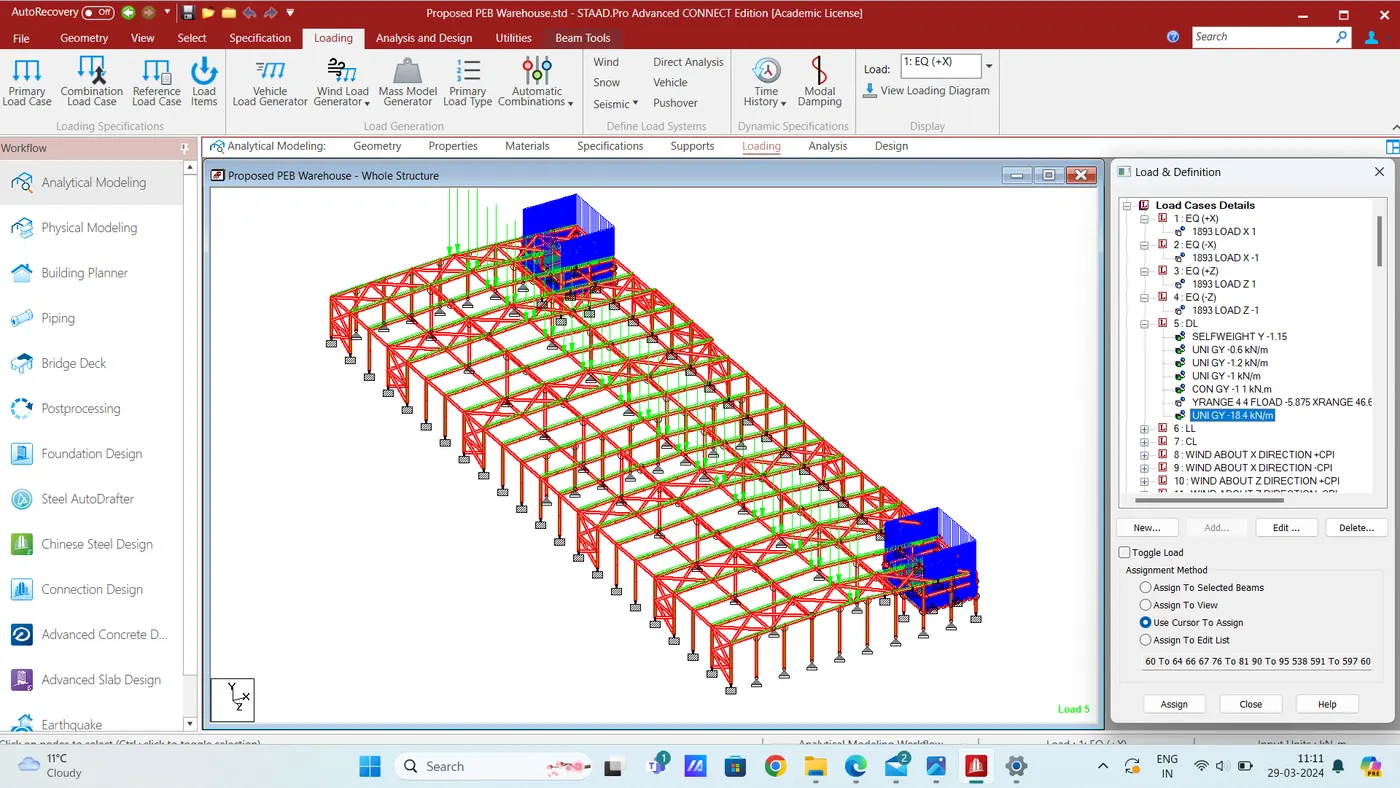
3) Mezzanine Floor – Load due to 230 mm thick and 4 m height wall around the periphery of Mezzanine Floor.
= 20 X 0.23 X 4 = 18.4 kN/m (on Both Mezzanine Floor)
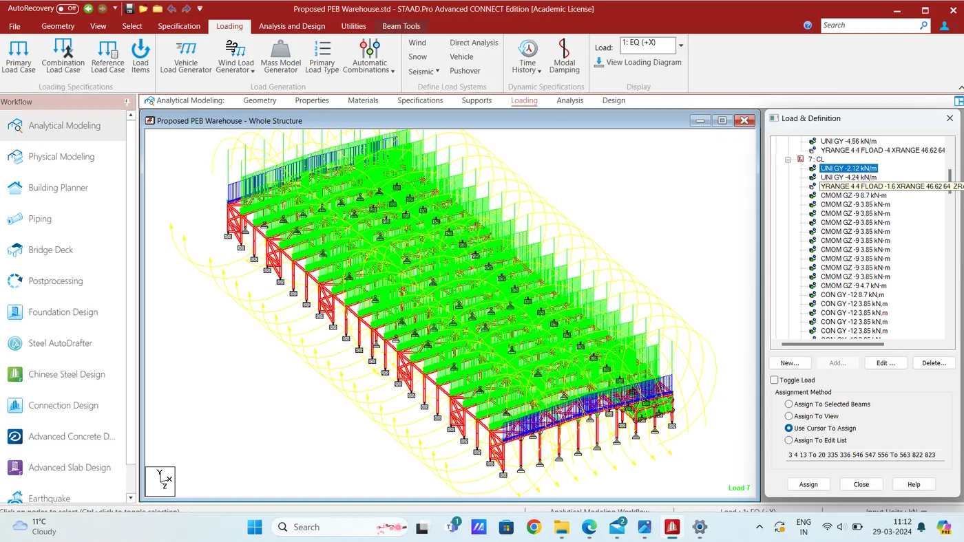
Collateral Load:
On Gable frame - 2.12 kN/m
On Main frame - 4.24 kN/m
Live Load:
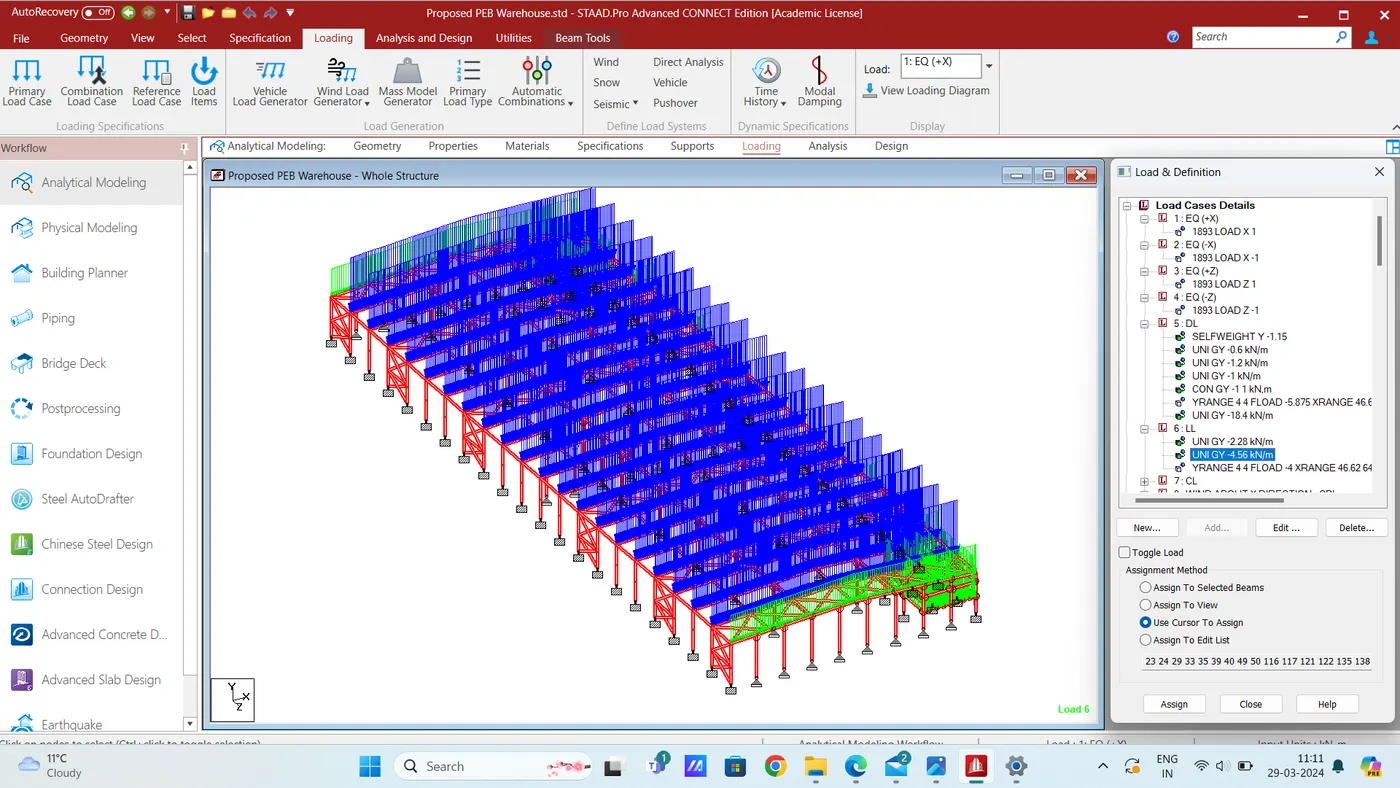
On Gable frame - 2.28 kN/m
On Main frame - 4.56 kN/m
On Mezzanine Floor - 4 kN/m2 or MEMBER LOAD = 6.8 kN/m on all secondary beams except end beams where load will be 3.4 kN/n (4 kN/m2 x 1.78 m (spacing of secondary beams)
- MEMBER LOAD = 6.8 KN/m on all secondary beams except end beams
- MEMBER LOAD = 3.4 KN/m on secondary beams at ends
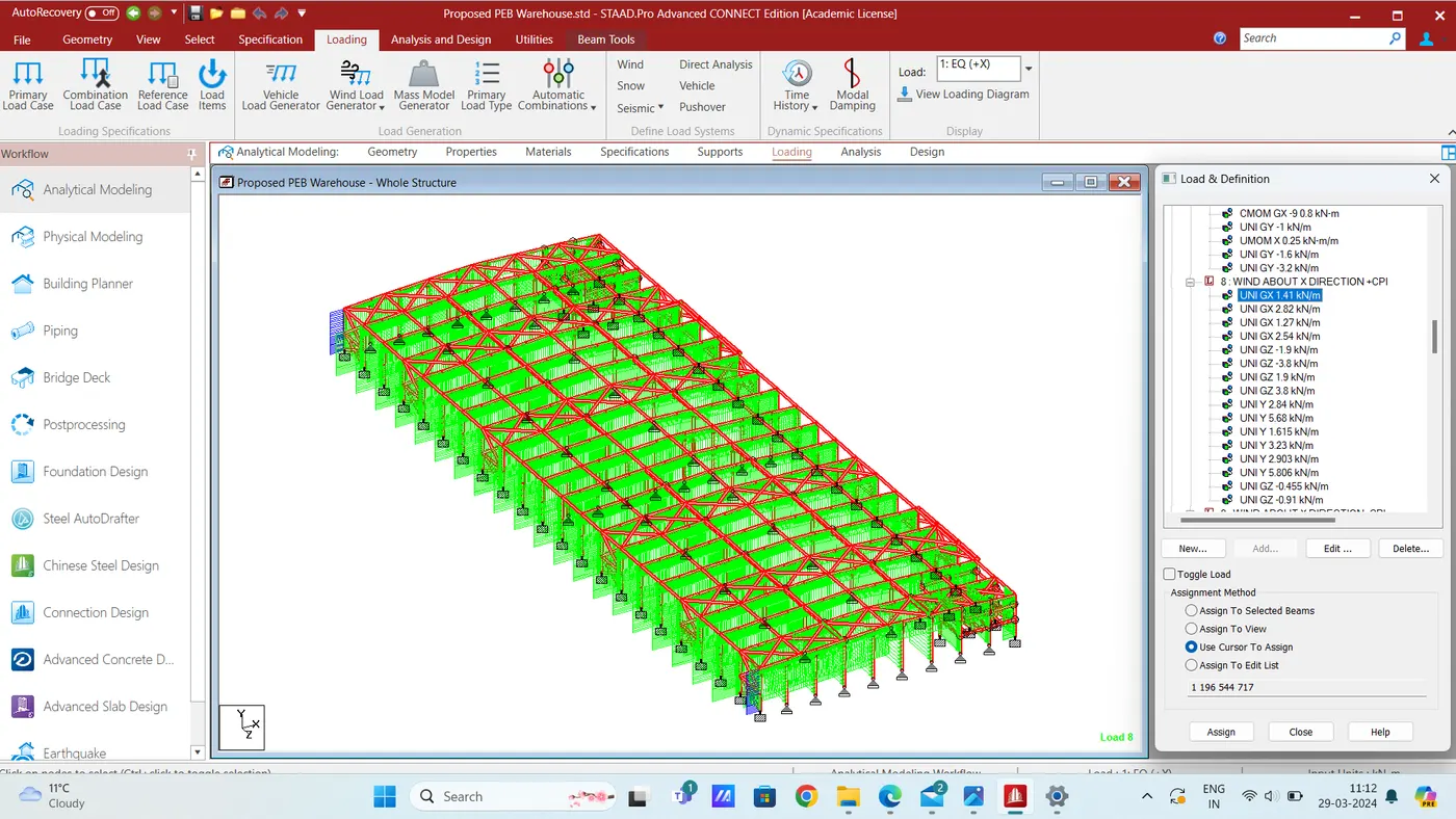
Wind load:
Basic wind speed = 39 m/s
K1 = 1, K2 = 1.05 (Terrain category), K3 = 1, K4 = 1 (Cyclonic zone)
Design wind speed Vz = Vb x K1 x K2 x K3 x K4
= 39 x 1 x 1.05 x 1 x 1 = 40.95 m/s
Wind Pressure Pz = 0.6 xVz2 = 0.6 x (40.95)2
= 1006.142 N/m2
Ka = 0.8245 (for column)
Ka = 0.8 (for rafter)
Kd = 0.9
Kc = 0.9
Ka x Kd x Kc = 0.8245 x 0.9 x 0.9 = 0.68 < 0.7 so taking least value as 0.72
Design Pressure Pd = Pz x Ka x Kd x Kc = 1006.142 x 0.7 = 704.3 N/m2
= 0.704 KN/m2
Cpi = ±0.2
h/w = 10.05 / 60 = 0.1675
l/w = 170 / 60 = 2.833
External pressure coefficient for walls for rectangular clad building From Table 5 of IS 875 ( part 3) for h/w < 1/2 and 3/2 < l/w <4
|
Wind Angle |
Cpe |
Cpe |
Cpe |
Cpe |
|
Wall |
A |
B |
C |
D |
|
0° |
+0.7 |
-0.25 |
-0.6 |
-0.6 |
|
90° |
-0.5 |
-0.5 |
+0.7 |
-0.1 |
External pressure coefficient for PITCHED ROOF of rectangular clad building From Table of IS 875 ( part 3) for h/w < 1/2
|
Roof Angle |
Wind Angle 0° |
Wind Angle 0° |
Wind Angle 90° |
Wind Angle 90° |
|
EF |
GH |
EG |
FH |
|
|
-0.86 |
-0.4 |
-0.8 |
-0.4 |
On Canopy:
Roof angle = 2.86 degree
Cp( -ve) = -1.08 (Uplift)
Cp (+ve) = + 0.35
Force on Canopy = -1.08x0.704x8 = 6.08 kN/m (upward)
Force on Canopy = +0.35 x 0.704 x 8 = 1.97 kN/m (downward)
For θ = 0° and Cpi = +0.2, Pd = 0.704 kN/m2, MF Spacing = 8m, EF Spacing = 6.75m.
Half of load acting in the Gable Frame
|
Surface |
Cpe |
Cpi |
Cp = Cpe – Cpi |
Wind force on frame |
|
A |
+0.7 |
+0.2 |
+0.5 |
+1.41 / +2.82 |
|
B |
-0.25 |
+0.2 |
-0.45 |
-1.27 / -2.54 |
|
C |
-0.6 |
+0.2 |
-0.8 |
-1.90 / -3.80 |
|
D |
-0.6 |
+0.2 |
-0.8 |
-1.90 / -3.80 |
|
EF |
-0.86 |
+0.2 |
-1.06 |
-2.98 / -5.96 |
|
GH |
-0.4 |
+0.2 |
-0.6 |
-1.69 / -3.38 |
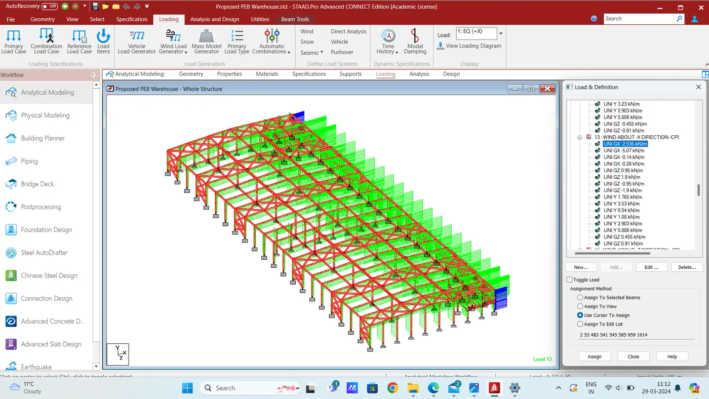
For θ = 0° and Cpi = -0.2, Pd = 0.704 kN/m2, MF Spacing = 8m, EF Spacing = 6.75m.Half of load acting in the Gable Frame
|
Surface |
Cpe |
Cpi |
Cp = Cpe – Cpi |
Wind force on frame |
|
A |
+0.7 |
-0.2 |
+0.9 |
+2.53 / +5.06 |
|
B |
-0.25 |
-0.2 |
-0.05 |
-0.14 / -0.28 |
|
C |
-0.6 |
-0.2 |
-0.4 |
-0.95 / -1.90 |
|
D |
-0.6 |
-0.2 |
-0.4 |
-0.95 / -1.90 |
|
EF |
-0.86 |
-0.2 |
-0.66 |
-1.86 / -3.72 |
|
GH |
-0.4 |
-0.2 |
-0.2 |
-0.56 / -1.12 |
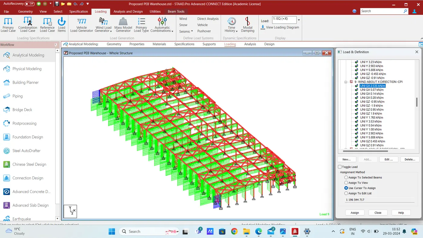
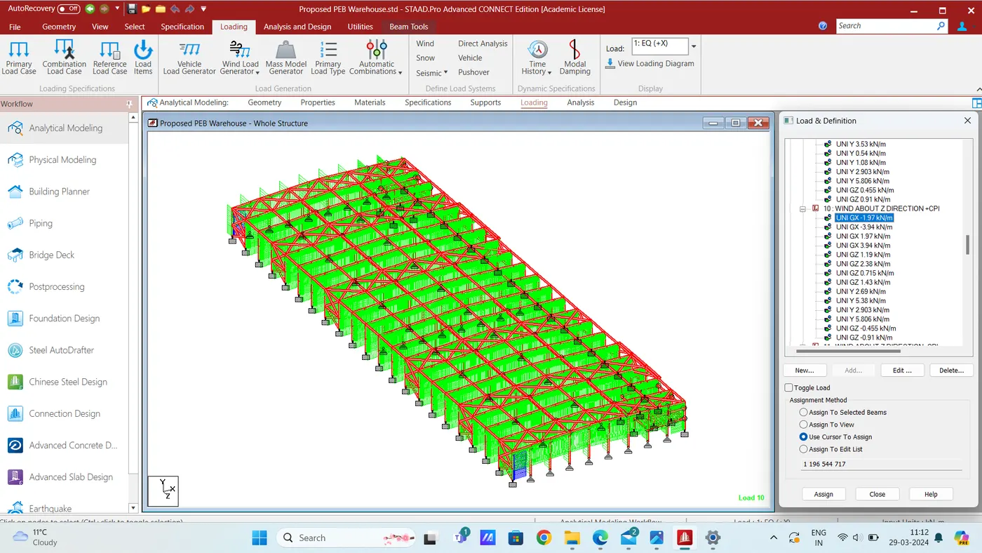
For θ = 90° and Cpi = +0.2, Pd = 0.704 kN/m2, MF Spacing = 8m, EF Spacing = 6.75m.Half of load acting in the Gable Frame
|
Surface |
Cpe |
Cpi |
Cp = Cpe – Cpi |
Wind force on frame |
|
A |
-0.5 |
+0.2 |
-0.7 |
-1.97 / -3.94 |
|
B |
-0.5 |
+0.2 |
-0.7 |
-1.97 / -3.94 |
|
C |
+0.7 |
+0.2 |
+0.5 |
+1.19 / +2.38 |
|
D |
-0.1 |
+0.2 |
-0.3 |
-0.71 / -1.42 |
|
EG |
-0.8 |
+0.2 |
-1.0 |
-2.82 / -5.64 |
|
FH |
-0.4 |
+0.2 |
-0.6 |
-1.69 / -3.38 |
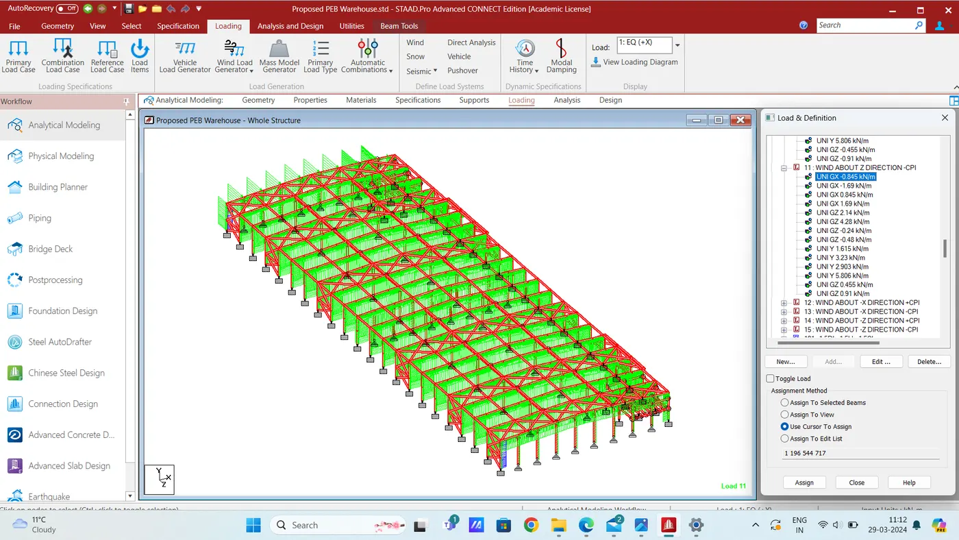
For θ = 90° and Cpi = -0.2, Pd = 0.704 kN/m2, MF Spacing = 8m, EF Spacing = 6.75m.Half of load acting in the Gable Frame
|
Surface |
Cpe |
Cpi |
Cp = Cpe – Cpi |
Wind force on frame |
|
A |
-0.5 |
-0.2 |
-0.3 |
-0.85 / -1.70 |
|
B |
-0.5 |
-0.2 |
-0.3 |
-0.85 / -1.70 |
|
C |
+0.7 |
-0.2 |
+0.9 |
+2.14 / +4.28 |
|
D |
-0.1 |
-0.2 |
+0.1 |
+0.24 / +0.48 |
|
EG |
-0.8 |
-0.2 |
-0.6 |
-1.69 / -3.38 |
|
FH |
-0.4 |
-0.2 |
-0.2 |
-0.56 / -1.12 |
Step 6:-
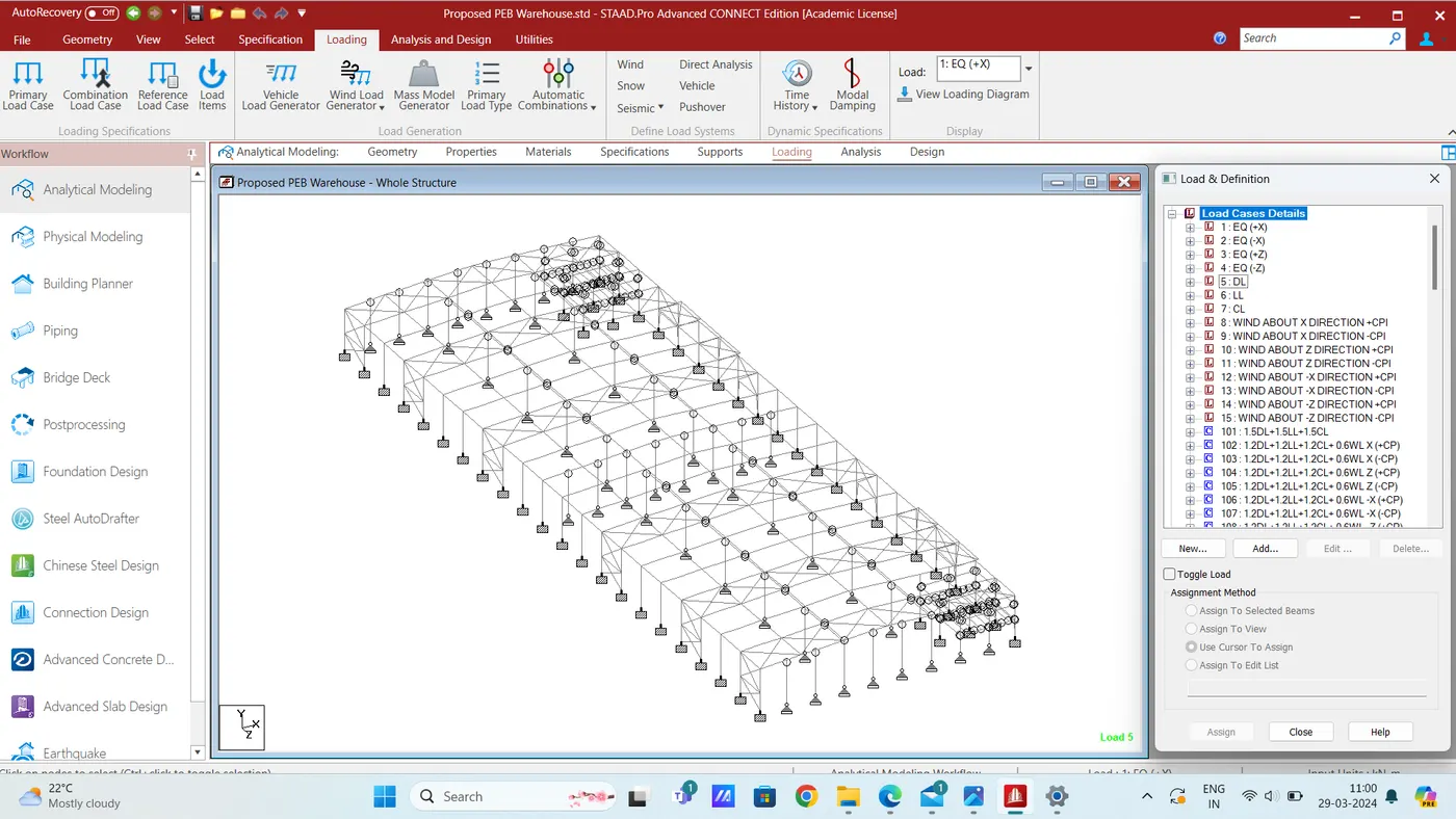
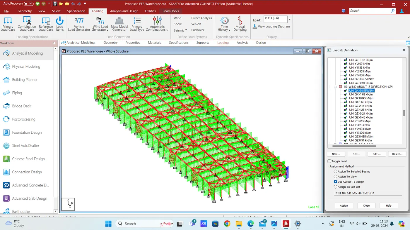
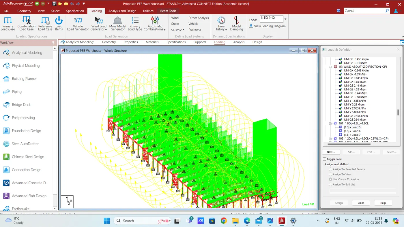
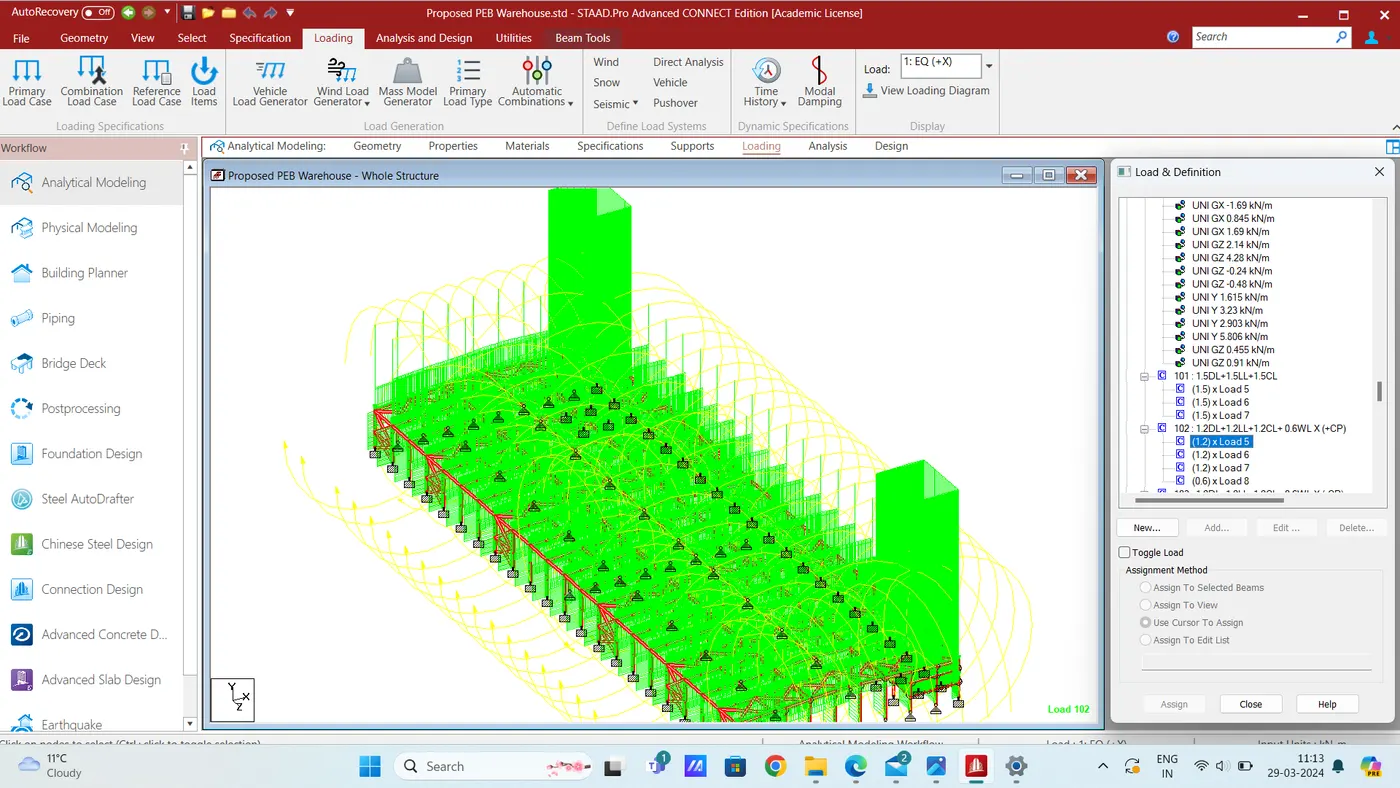
- Load Assignment and Load Combination creation and Assignment.
Step 7:-
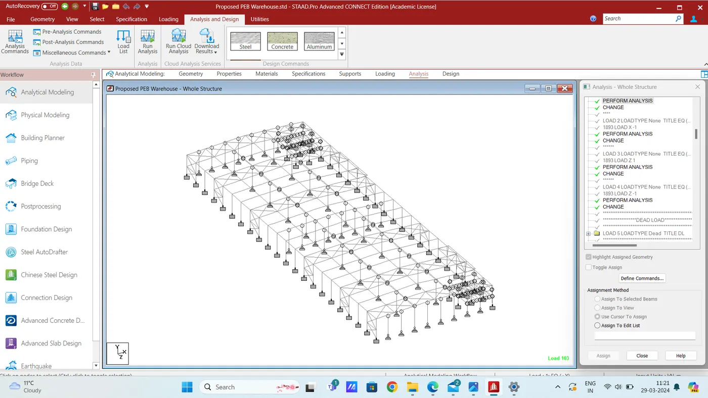
- In Analysis Tab, Create and assign Parameters to the Model.
Step 8:-
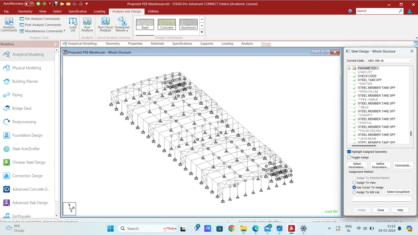
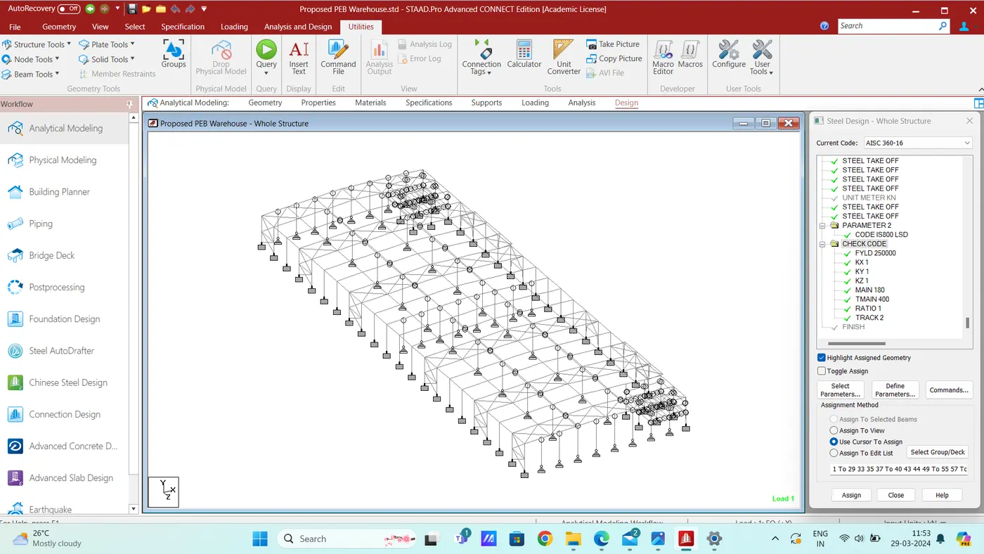
- In Design Tab, Create and assign Design Parameters to the Model.
Step 9:-
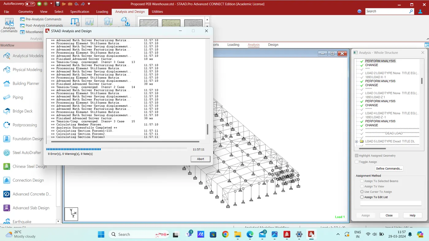
- In Analysis Tab, Click Run Analysis.
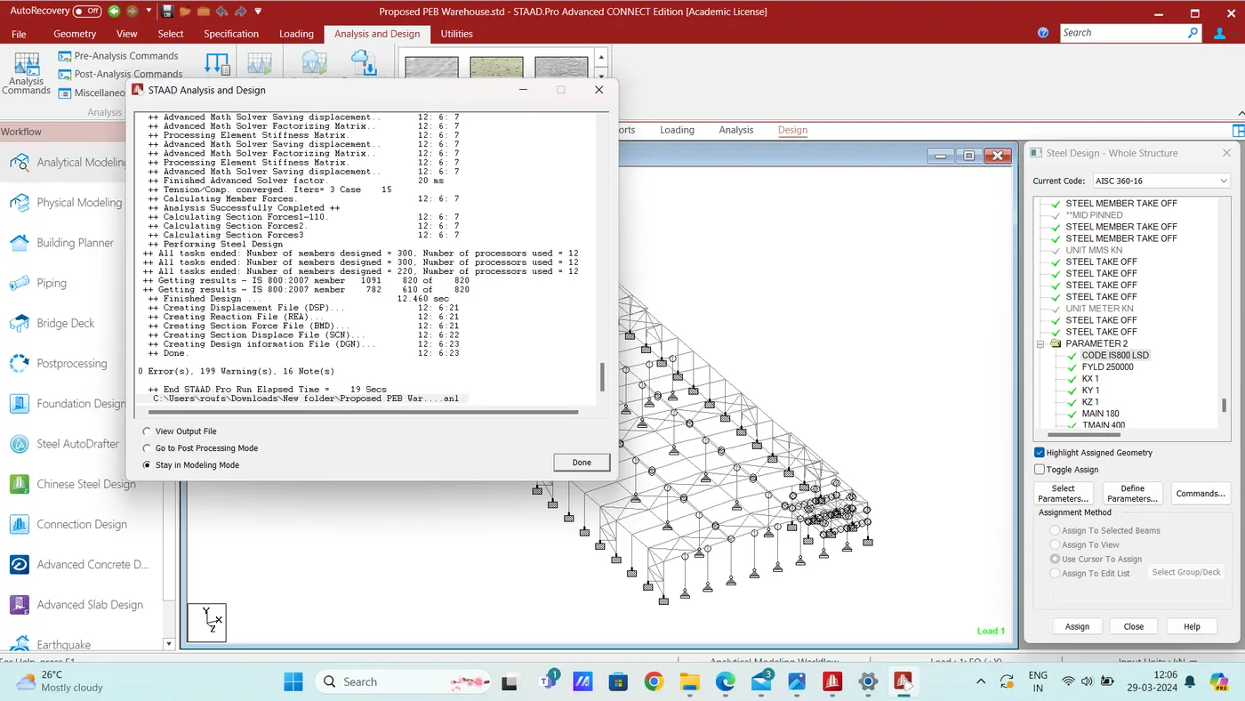
- The Proposed PEB Building was Modelled and Designed using STAAD Pro successfully.