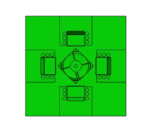
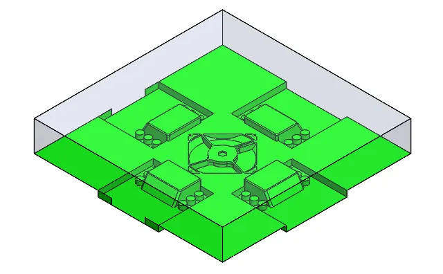
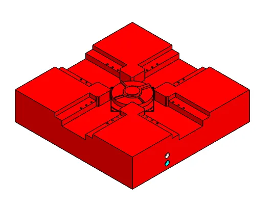
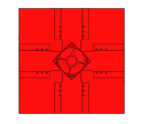
Project 2
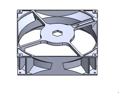
Aim: - In this project, Based on the content covered up till now, I have to create a proper mold for the model Design of CPU fan Bezel. Assume the material to be ABS (shrinkage - 0.6%).
Objective: - Know about the draft analysis, shrinkage allowance, parting line, shutoff surface, create core-cavity surface and blocks, assembly, relief, ejector pin, ejector plate, ejector back plate, runner and gate, air vent and cooling channel.
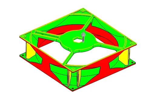
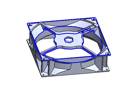
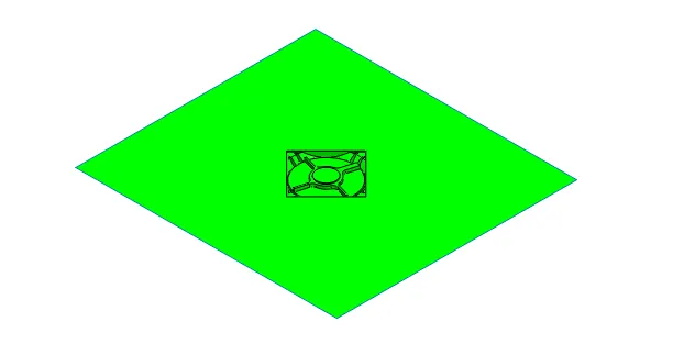
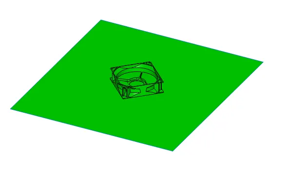
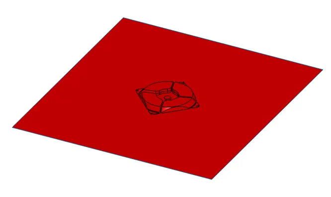
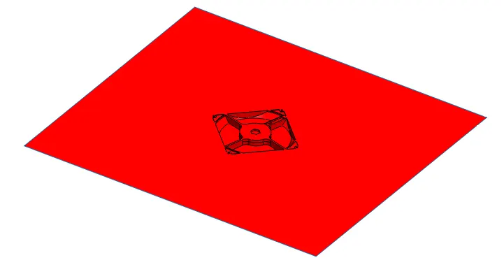
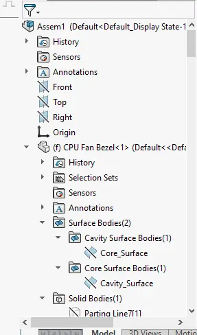
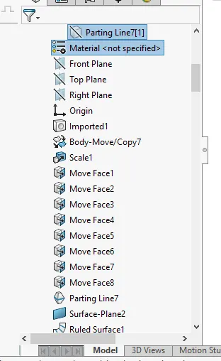
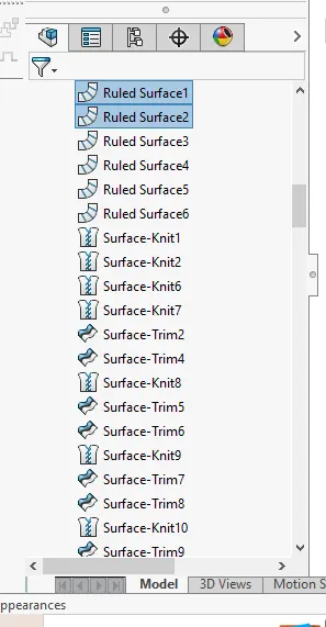
Procedure: - Firstly check the draft analysis of the fan bezel component. after that use scale command to increase size of the model to according for the shrinkage then go for parting line command to create the parting line the core-cavity separation, however use shutoff surface to close the holes and create the core-cavity surface, then use ruled surface command to manually create the parting surface and merge the parting surface with core-cavity surface to create final core & cavity surface.
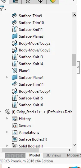
Before that keep a copy of parting surface then use Knut the core-cavity surface with planer surface individually. With the help of this procedure made the core-cavity surface.
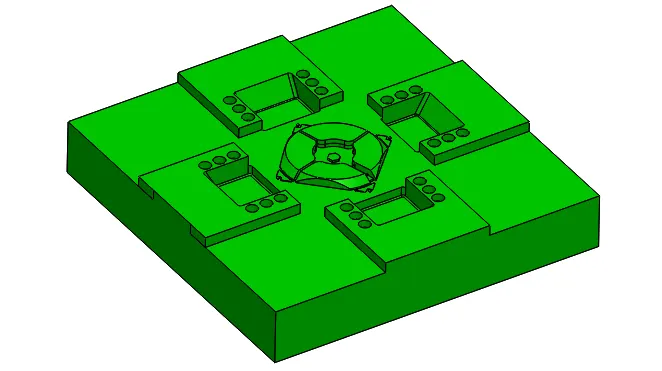
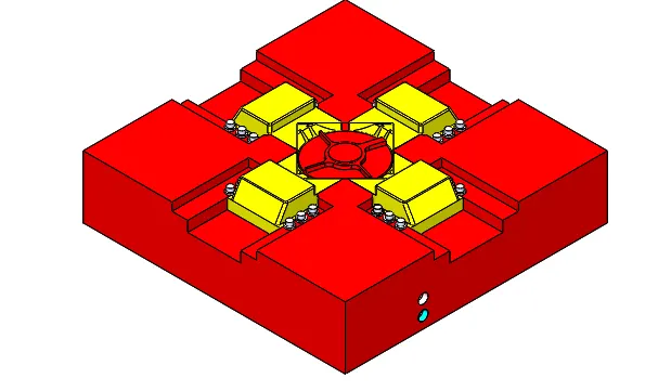
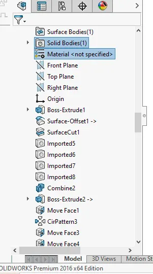
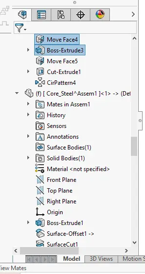
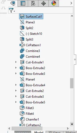
Assembly:- Make new part Core and cavity steel block: firstly set the alignment of spruce then use the top plane for create a sketch and extrude, again make a top plane sketch and split into two solid part. After that use offset command for cut with surface block. And correct according to standard dimension of the block. In the end create a core-cavity block and provide relief in the cavity block.
Firstly create insert for mold block: - first of all check the dimensional distance. For separate need create a sketch and a reference plane. Used split command cut bodies so inserts created separate. Makes cut for bolts so used counter bore holes type.
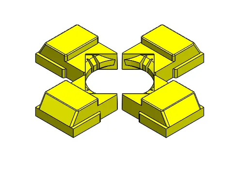
Slider:- Firstly checked through the section analysis founded that undercut due to the inclined line. Create a sketch on the top face entire feature then create reference plane and used split command split to create separate to core block.
Check undercut using draft analysis and create another split body due to unwanted feature. Now assign the colour to different part. Then another extra thin issue resolved through edit the sketch.
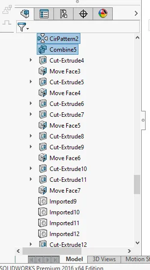
Ejector pin & plate: - Frit I have create hole for pin in the core block. So create a sketch on a flat face and used extrude cut command. Then ejection pin for mold so used same sketch which is used for hole cut but now used extrude boss command. And provide relief on the top face. After that make head for ejection pin.
Ejector plate: - used pin head for ejector plate make a sketch which is same length of core block and width is 45mm less from both side then extrude 10mm as a separate solid body. Make some cut used convert entities and make same dimensional ejector back plate.
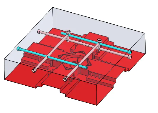
Cooling channel: - objective of achieve cooling uniform channel thought out the mold. It’s depend on plastic material, thickness, coolant, and many more etc.
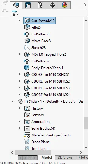
Therefore we directly used to hole wizard command, socket head screw head type holes.