Project 2
AIM:
To route the wiring harness bundle for the given body.
Objective:
- The main objective of this project is:
- To create the wiring harness routing for the given Car body by using appropriate connectors, clips and clamps which is required.
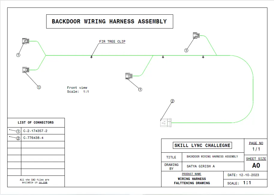
- To create a flatten view drawing file in Catia v5.
- Need to apply the protection covering like cot tubes and insulation tapes to the bundles as required.
- Need to apply the industry best packaging rules and best practices studied in this course.
Packaging rules and assumptions made in this project:
- Avoid harness routing and clipping in a blind zone.
- Avoid harness routing through the small structural holes and openings to minimise the chaffing and handling of the wiring harness during installation.
- Provide additional slack to the harness according to the surrounding and harness bending requirements. And avoid excess slack to the harness.
- Provide sufficient clearance to the different surrounding parts.
- Avoid routing over the bolts, near to the bolted joints or screwed joints. Because it may damage the harness or may puncture the harness.
- Avoid routing near the sharp edges like thin sheet metal brackets, panel joints, etc.
- Provide at least 100mm clearance to the harness from the ABC pedals, clutch lever & cables, Engine timing belt or any other dynamic components.
- Enough clips and clamps should be provided to ensure the positive clearance with the surrounding and safety of the wiring harness.
- Ensure distance between two clamps on a straight branch should be maximum of 200mm.
- Clamping requirements should be decided based on the harness bending, surrounding and mounting arrangements.
- Provide positive clamping at the engine and chassis to avoid the harness damage when Engine rocks.
- Keep harness away from the transmission dynamic assemblies like drive shaft or propeller shaft.
- Provide the guiding channel if it is required.
- Use the rubber gromets which provide the proper sealing, and also protects the harness from the sharp edges and absorbs the vibrations.
- Wiring harness minimum branch length should be 50mm.
- Minimum distance between the clip and nearest branching point should be atleast 25mm.
- Minimum distance between two breakouts should be 50mm.
- Limit the number of branches coming out from the single branch to 4.
- Provide the bracket for the interconnection connector parking.
Steps followed for creating the wiring harness routing to the given V-16 Engine:
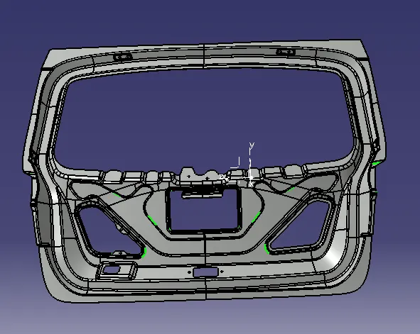
STEP 1: Download the cad files of the given car body, connectors, clips and clamps.
CAR BODY (TAIL GATE ):
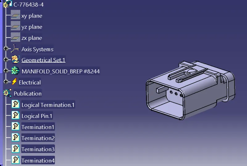
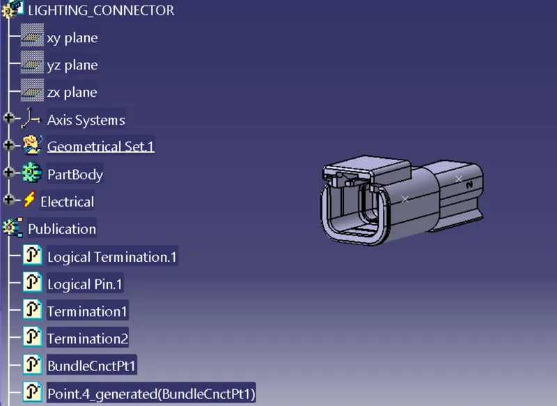
Defining all the connectors as electrical components and the clips as the supporting equipment.
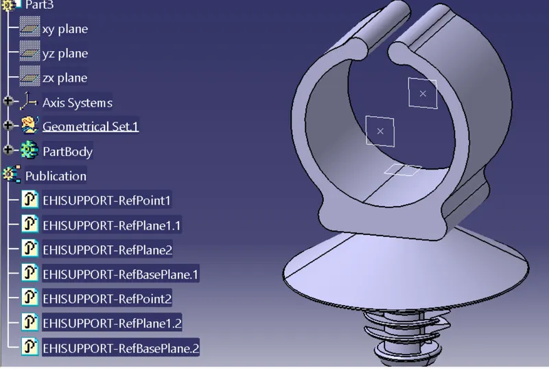
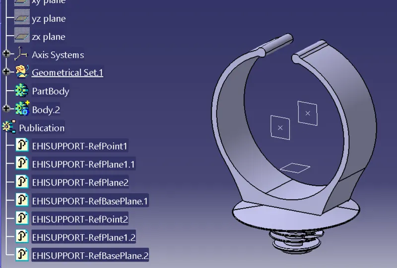
ALLIGNING CONNECTORS AND CLIPS TO THE BACK DOOR:
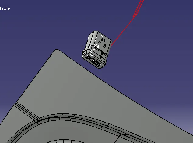
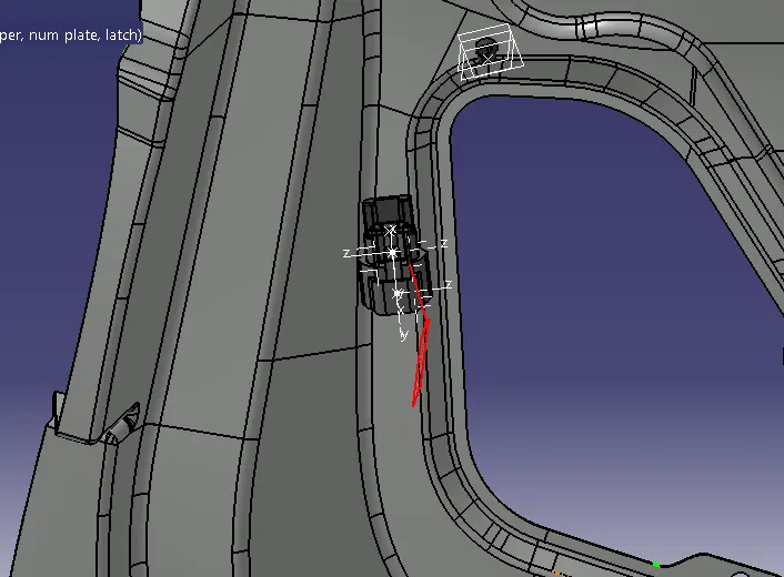
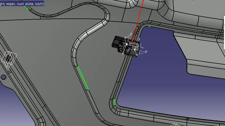
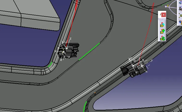
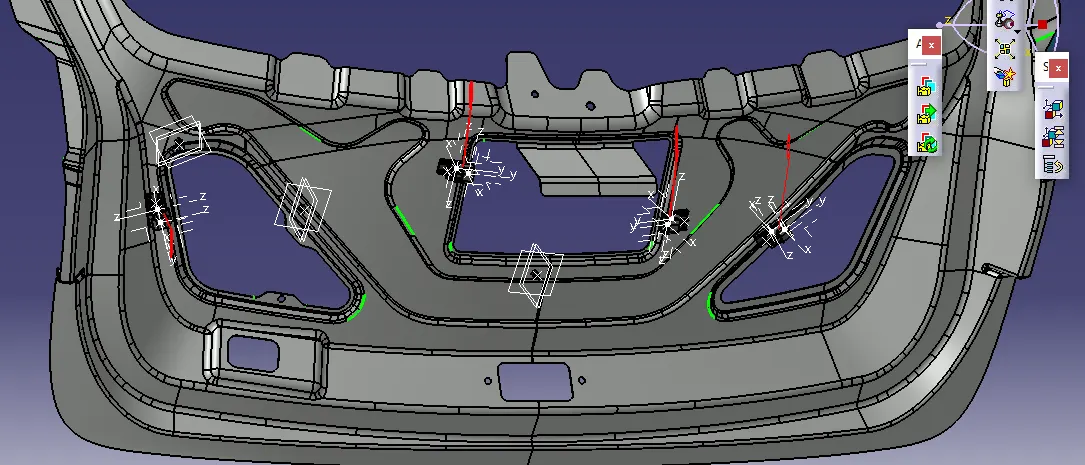
ROUTING THE WIRING HARNESS:
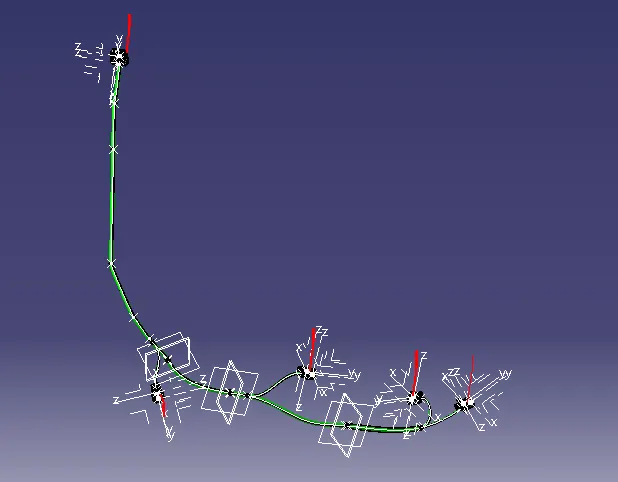
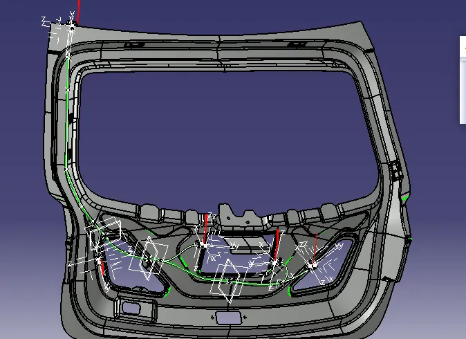
Preparing the flattening view of the wiring harness assembly
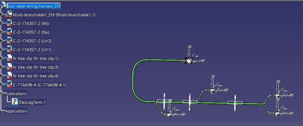
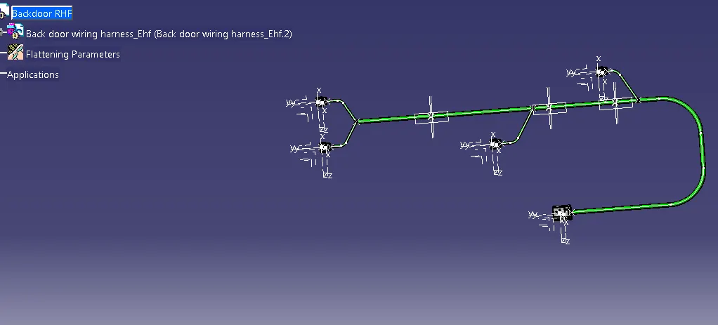
DRAWING FILE FOR WIRING HARNESS ASSEMBLY: