Project 2
Creating Context Assembly
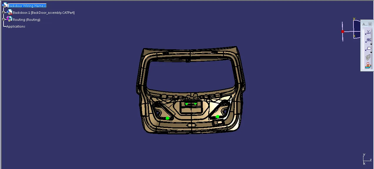
We have created context assembly for the tail gate of the car as main assembly as shown in above figure.This context assembly contains the 3D cad data for the tail gate of the car and car tail gate harness geometrical bundle.
Difining 2-pole and 8-pole connectors electrically
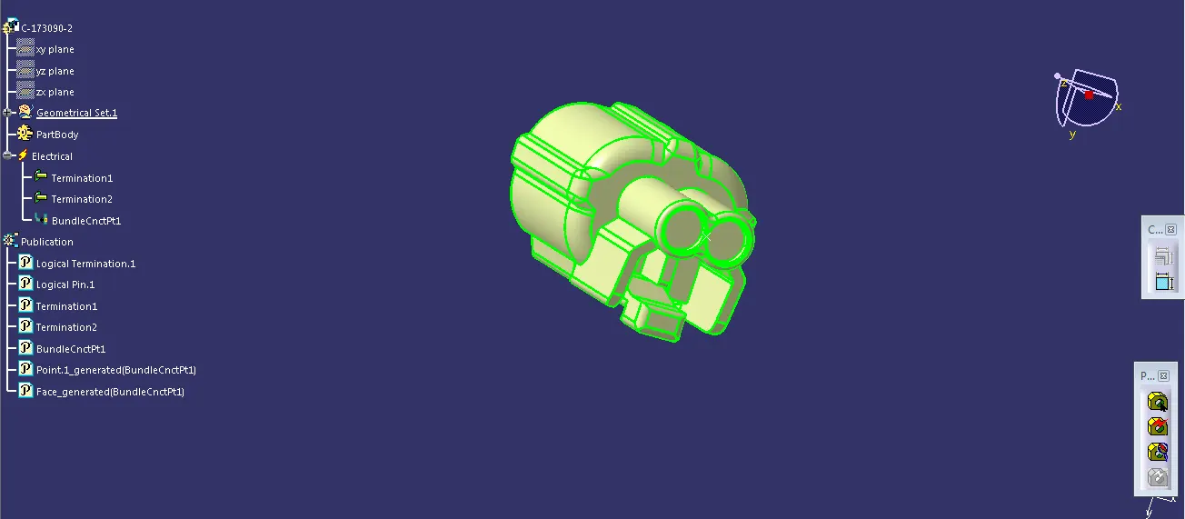
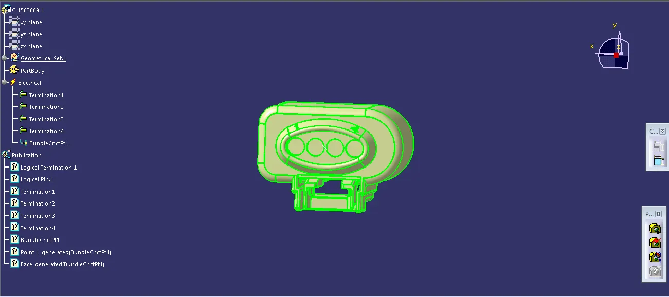
Here, we will use 2-Pole and 8-Pole connectors for this assembly and for that we have downloaded these connectors from TE.Com
We should have to define it electrically that is to define geometrical parameters, bundle connection point and connector connection point.
Adding connectors to the 2 tail lights and 2 number plate lights
We have added both 2-pole connectors and 8-pole connectors inside the tail gate harness geometrical bundle assembly.
We have used commands like manipulation, compass, snap and smart move to place all the 4 connectors to their desired location.
Defining and locating interconnection connector
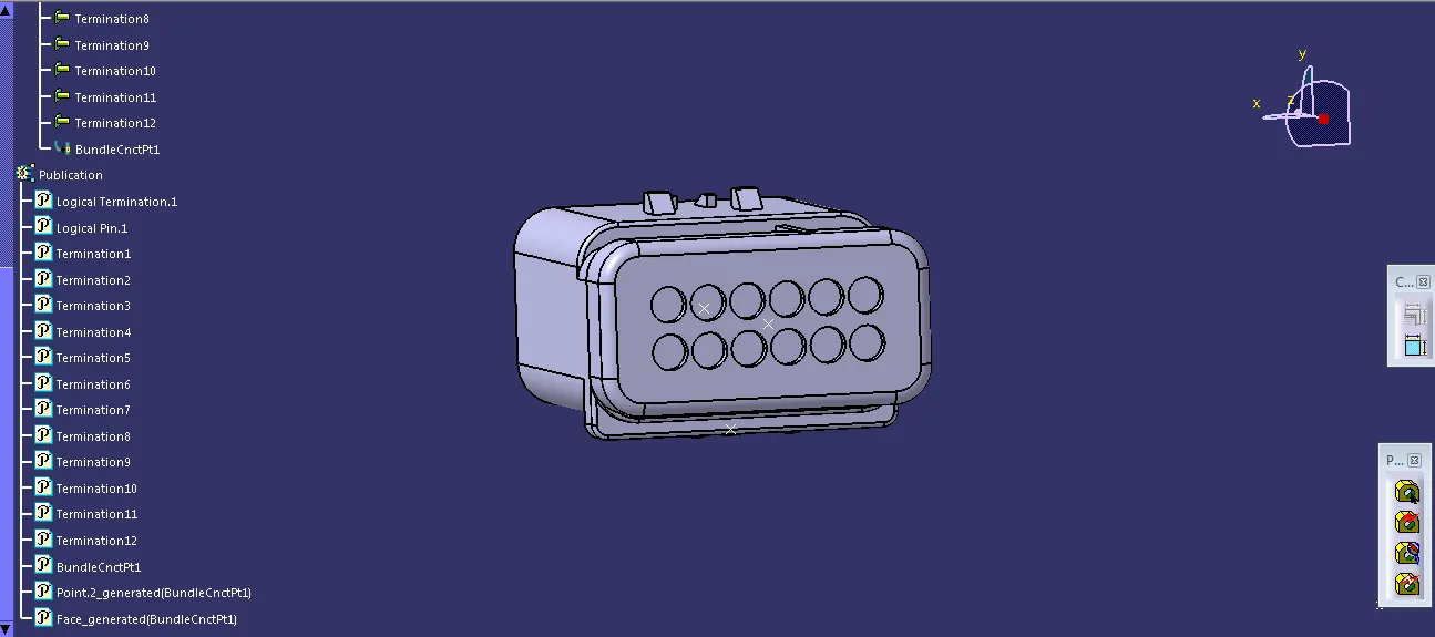
A 12-pole "C-776438-4" is used as an interconnection connector and "C-1924487-2" as mounting cavity.
The 3D CAD data files for interconnection connector and cavity are downloaded from TE.com
we have electrically connected both an interconnection connector and mounting cavity in Electrical Assembly Design workbench.
After defining an interconnection connector electrically, we have mounted it near top slot on the tail gate of the car
Defining mounting clips as support
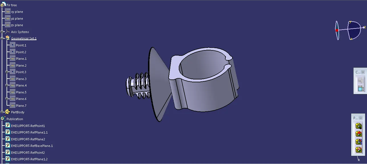
We will be using Hellermann Tyton mounting clip for the mounting purpose.
We have to define geometrical parameters, bundle entry points and exit points from both left and right side of the clip.
We have defined these clips electrically as a support in Electrical Part Design workbench as shown in below figures.
Mounting Clips at desired location
we have used 6 bundle clips which have mounted at desired location
Bundle routing
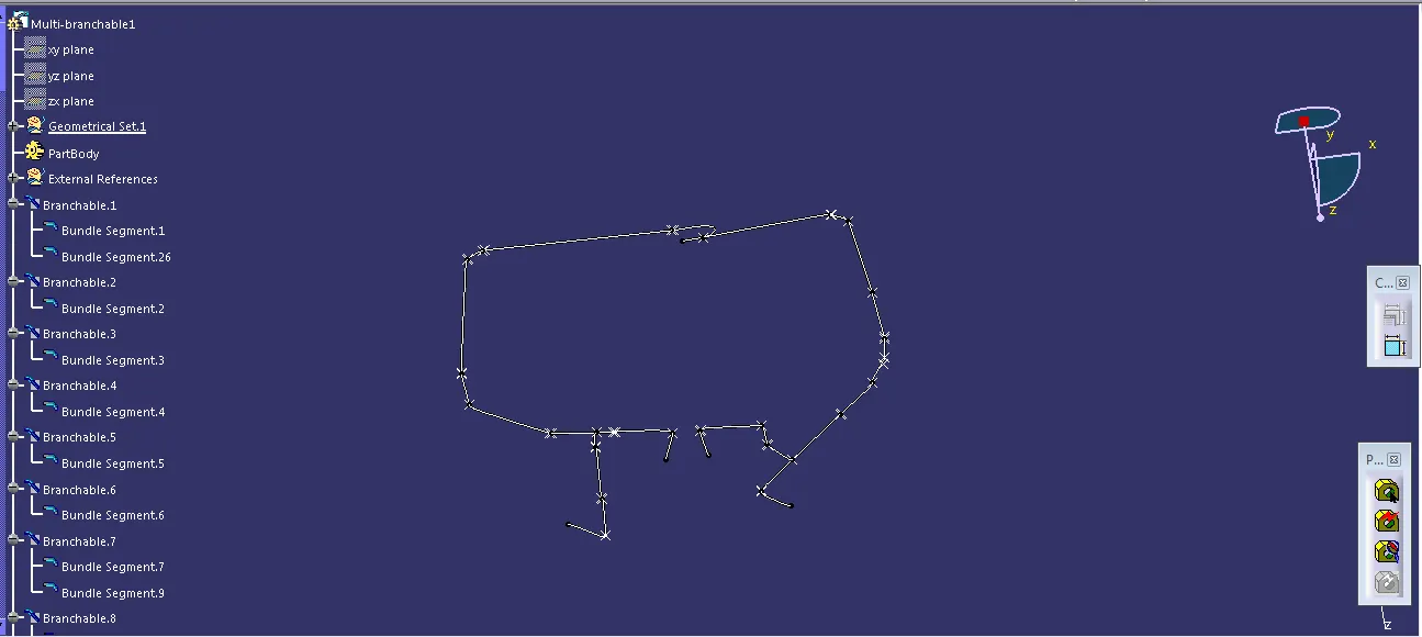
Before, bundle routing we have to make a curve by creating points in hollow part of the given tailgate. So we have made a curve through 11 points from the interconnection connector
Now, the car tail gate assembly is ready for the bundle routing as shown in below image.
Also, we have activated harness assembly as geometrical bundle.
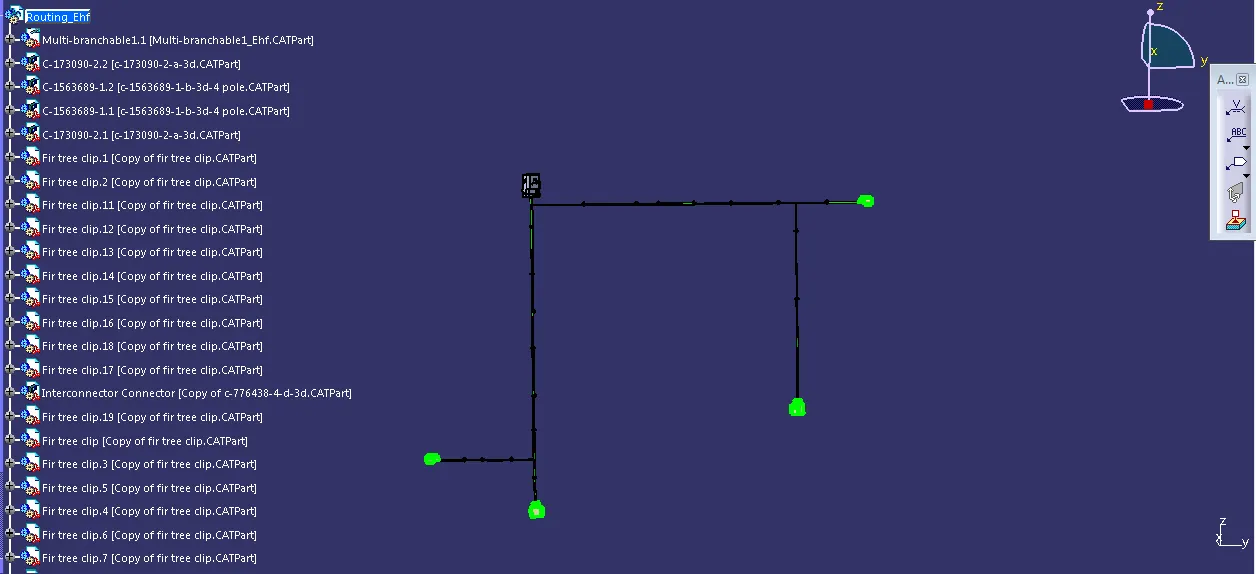
Let, we have started bundle routing from interconnection connector and assumed diameter of main trunk is 12mm.
The diameter of bundle leading to 2 tail lights and 2 number plate lights is 8mm and 5mm respectively.
The bend ratio is assumed to be 1.4 and appropriate slack between 1-10% is given wherever needed.
Adding protective covering to the harness bundle
After bundle routing, we have to add protective covering to the harness bundle so that it will get protected from the damage.
Here, we have used PVC tape for the current harness assembly.
We have given start and end extremity wherever needed for the PVC tape
Create flatten view of the wiring harness bundle
To create a flatten view of the harness assembly, we have to work in Electrical Harness Flattening workbench in Catia V5.
Also, we have to make sure that the flattening file is saved into the same folder where we have all the parts of the harness assembly.
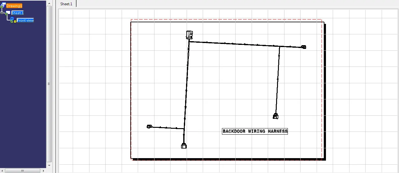
As shown in below image, while defining the wiring harness flattening parameters make sure to select Single line for bundle segment and Double line for protective covering.
After that, we have to extract and bring the bundle assembly into the car tail gate flattening product file