Project 2
AIM:
To design different types of fixed pin units and retractable pin units with different pin, riser, blade, cylinder, and block
FIXED PIN & RETRACTABLE PIN UNIT
A fixed pin unit is a unit designed to locate the car panel using pins. Pin, pin retainer, shims, blocks, blade, riser are the part of fixed pin units in general. pin a retainer is used to hold the pin firmly
A retractable pin unit is a unit designed to locate the car panel using pins, but the entire pin package parts will be mounted on the retractable pneumatic cylinder, pin, shims, L Block, pneumatic retractable cylinder, riser are the parts of retractable pin unit
MATERIALS USED: In general, the materials used for pins, pin retainers, shims, shim block, blades & risers are:
- Pin: C45, EN31, SAE 8620 Steel, etc.
- Pin retainer : Steel / ASTM A-36, SS type 303 or 304, etc.
- Shims/spacer: S.A.E. 1010 CRS FULL HARD, COLD ROLLED STRIP STEEL S.A.E. 1010 FULL HARD, S.A.E. 1020 HRS, etc.
- Shim block : STEEL ASTM A-36, NM Stainless, STEEL ASTM A-36, SS type 303 or 304, etc.
- Blade : STEEL ASTM A-36, etc.
- Riser : STEEL ASTM A-36, etc.
HARDNESS
- In general, the hardness of the materials for pins, pin retainers, shims, shim block, blades & risers are 55 - 60 HRC / 58 - 62 HRC to a depth of 0.5 - 0.7 mm after grinding.
PIN TOLERANCE
- The pin tolerance for a geo pin will be of closer tolerance i.e. -0.15mm & for re-spot pin is of -0.28mm
PURPOSE OF PIN UNIT
- As by the 3-2-1 locating principle, the introduction of two pins helps to arrest the 6 degrees of freedom (4 axial & 2 radial movements) whereas the other 6 degrees of freedom are arrested by introducing a minimum of three supports.
- Typically, the locating pins are used to locate a body part in a position sufficiently accurate to execute a welding process.
- The body part is constrained by a set of appropriately locating pins so total constraint by locating pin should be fully constrained at all times to prevent any movement
FUNDAMENTALS OF PIN UNIT DESIGN
It is necessary to have two pins to locate a car panel. And here one pin must arrest 4 ways (i.e. 4 translations) & other must have arrest 2 way (i.e. 2 rotational) of a car panel.
- Pin should engage 3 to 5mm from the car part entry surface.
- All pin should be accommodated with 2-way adjustable shims irrespective of the direction of arresting.
- Round pin should be used in case of 4 way arresting of the car panel if the hole is round.
- Round pin can be used for 2 way arresting of car panel only if the hole is slot.
- Diamond pin should be used in case of 2 way arresting of the car panel if the hole is round.
- Diamond pin should be used in case of 4 way arresting of the car part if the hole is slotted.
- The axis of the car panel hole & the axis of the pin should be the same in general
PARTS USED IN PIN UNIT DESIGN
- Pin
- Pin retaine
- Shims
- L-block/shim block
- Blade
- Riser
PIN
- It is used for the location purpose of the panel.
- Typically, the locating pins are used to locate a body part in a position sufficiently accurate to execute a welding process.
- The body part is constrained by a set of appropriately locating pins so total constraint by locating pin should be fully constrained at all times to prevent any movement.
- There are dozens of styles of locating pins that can be utilized in a design.
- A pin can either be a make part or a standard part also. Below I have shown the commonly used pins.
- One of the most common pins is a stepped pin with either a small or large head.
CONSIDERATION
- The pin should have a grinding surface on the shaft with fits on to which the pin retainers will be fitted.
- The mounting surface of the pin should be a finely machined surface.
- A pin should have a step machine surface to lock the rotation, which matches with the pin retainer.
- The mounting surface of the pin retainer to the blocks should be a machined surface.
- All machined planes should be perpendicular to the axis of the pin shat.
- Pin must have a fastening provision like a tapped hole from the bottom or a v- grove from the side.
- A pin must be hardened ( 55 - 60 HRC) & black oxide finishes in general.
PIN RETAINER
A pin retainer is a part that holds the pin in position, the pin retainer can either be a make part or a standard part also pin retainer is used to hold the locating pins firmly.
CONSIDERATION
- A pin retainer is a part that holds the pin in position, the pin retainer can either be a make part or a stand Pin retainer should have a hole with a fit, on to which the pin will be fixed.
- The pin mounting surface of the pin retainer should be a finely machined surface.
- The pin mounting surface of the pin retainer should have the step to lock the rotation of the pin.
- The pin mounting surface of the pin retainer to the blocks should be a machined surface.
- The pin retainer will be fixed to a block or an L - block to the riser with 2 dowel holes & at least with one screw hole to maintain the tolerance and part also
- pin retainer is used to hold the locating pins firmly
SHIMS
- Shim is generally used to adjust the design to manufacturing deviation.
- In general, a shim is a thin and often tapered or wedged piece of material used to fill small gaps or spaces between objects
- Shims are typically used in order to support, adjust for better fit, or provide a level surface.
- Shims may also be used as spacers to fill gaps between parts subject to wear.
- Shims are the small parts that come with thicknesses of 0.1mm,0.2mm, 0.5mm,1.0mm, etc.
- These will compensate for the stack-up tolerance which reflects at the mylars.
- We give tolerance to all parts of the fixture. Due to this tolerance, the mylars will either lift up moves down from their defined position.
- To adjust the mylars for getting the defined position we use shims.
- Shims will be added above the mylar for adjusting according to tolerance.
APPLICATION
- In automobiles, shims are commonly used to adjust the clearance or space between two parts. For example, shims are inserted into or under bucket
tappets to control valve clearances. Clearance is adjusted by changing the thickness of the shim. - In assembly and weld fixtures precision metal shims are used between two parts so that the final production parts are created within the product
drawing's specified tolerance.
L-BLOCK/SHIM BLOCK
These parts are mainly used to accommodate the shimming directions as per fundamental in general also in some cases used for other design feasibility.
BLADE
- Blade is a part like a plate, which connects the parts of a unit to a riser. In general, the blade can either be a making part or a standard part.
- Blade is the plates that are attached to the raiser.
- Blade is also attached or mounted with cylinders, arms etc
RISER
Riser is a manufacturing part used to raise/height the assemblies of fixtures. One end of the raiser will be attached to the base unit while the other end will be attached to the Blade. It is a part on which all the parts of a unit are mounted on the base plate of a tool. In general, the riser can either be making a part or standard part.
Raiser can be of two types. They are,
- "L' type risers.
- Square tube risers.
CLAMP UNIT:
Clamp Unit is used to clamp or hold the car panel or component in a fixture with the help of mylars or NC blocks using manual or pneumatic clamp cylinder. This unit only restricts the up and down motion of the car panel.
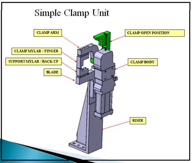
Different parts used in clamp unit:
1. Clamp Mylar/ Finger/ NC Block: This part is in actual contact with the car panel as it holds or clamps the component.
2. Rest Mylar/ Finger/ NC Block: This part also is in actual contact with the car panel as the car panel rest on this part as shown in the above image.
3. Clamp Arm: Clamp Arm is the part on which clamp mylar is mounted. Basically, this is the standard part that comes with the cylinder.
4. BLADE: As shown in the figure blades are bolted on the riser.
5. RISER: Riser is used to increase the height of the unit and these are standard parts so need not detail it or design it.
6. Shim/Spacer: Shims or spacer are used to compensate tolerance stack up. In the clamp unit, we need to control only one direction that is z using shims or
spacer. Shims are generally thin sized plates used in groups called Shimpack and spacer are used as a single plate and can be machined accordingly
REST UNIT:
The Rest unit is used to give support to the car panel or component. Hence also known as a support unit. It consists of a riser, rest mylar, and shim or spacer for upward or downward adjustment.
AIM: To design the base unit and all the necessary fixtures to the given component
Base Unit
A base unit is a unit designed to mount all other units (Clamp unit, pin unit, rest unit, etc) of the tool, also other parts necessary for a tool like pneumatic valve box, trunking cable path will also be mounted onto a base unit.
The base unit is the fundamental component of the fixture because all other components are mounted over it so every fixture has a base unit. The base unit design is different according to the panel design of the clamp system, location system, etc.
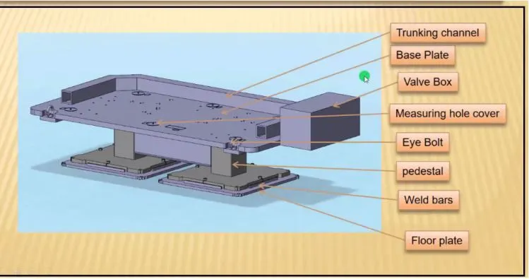
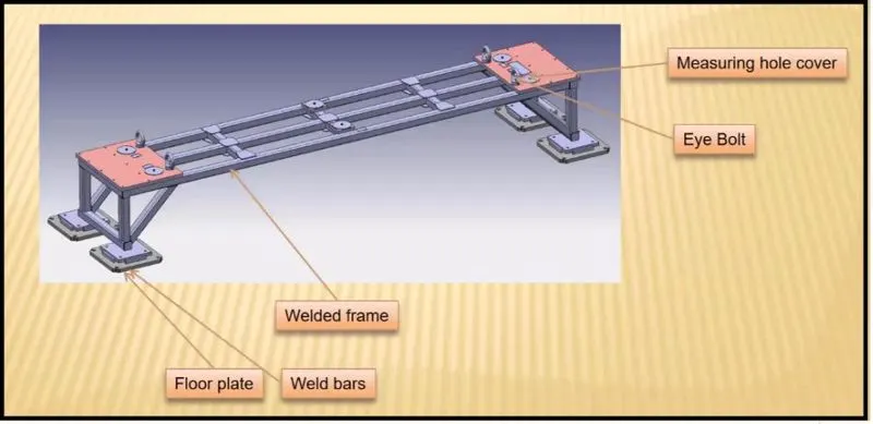
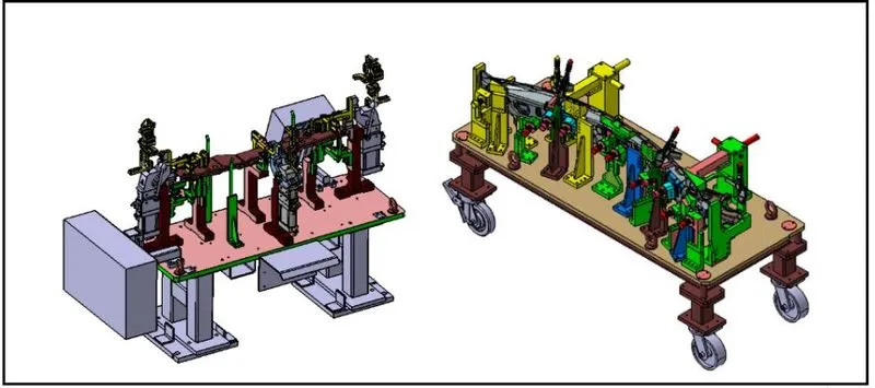
Typical parts of base units are given as follows,
a) Baseplate:
The base plate is a machined plate of 25 to 40 mm thickness made of steel & aluminum, on to which the holes are drilled to mount the individual units like clamp units, pin, etc., of a tool.
b) Pedestal: A pedestal is a part that connects the base plate to the floor plate. A pedestal is a standard part in general & in some cases, it can be a welded frame integrated with the base plate.
A standard pedestal can be of different heights & different sizes. Depending on the size of the base plate, the number of pedestals varies for load distribution. A pedestal is of different types with different inclinations.
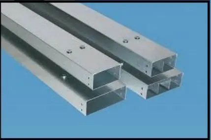
c) Trunking Channel: A trunking channel is a duct that accommodates all the pneumatic & electrical hoses and wires for the units of the tool. It has a thickness of
few millimeters.
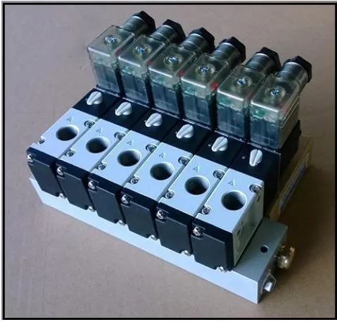
d) Valve box: The valve box is the standard part that will accommodate all the pneumatic valves for the units. The valve box is the box that includes different solenoid valves. The pneumatic fixtures work on air pressure provided to it. So the arrangement of air pressure inlet & outlet is done within this valve box. The trunking channel includes all the pressure inlet cables going to pneumatic parts of the fixture & protects them from damage while the operation is in process.
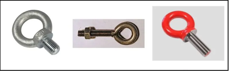
e) Eyebolt: Eyebolts are used for the transporting of the tool, using lift hooks, forklift holes will also be provided in some areas for transporting purposes. For example, we usually use M20 bolts that are bolted on the base plate.
f) Floorplate: The floorplate is grouted to the floor with a fixed bolt on the ground. Floor plates are also called as foundation plates
There will be a clearance of 10 mm maintained between the pedestal base plate & floor plate.- This clearance will be used by the leveling screws, for leveling the entire tool.
- Weld bars are be used to weld the positions permanently after leveling is done.
- A weld bar is a plate along the sides of the base plate of the pedestal
Considerations for designing a Base unit
a) Working height:
It depends on the nature of the manual or robotic welding fixture. For manual fixtures we need to consider the working height 850-1100 mm, depending upon the working height of the worker standard of a specific country will apply (in few countries human height is higher or lower e.g. (US, Japan).
If the base structure is made with a base plate having a tubular structure welded below it we can reach to the height of 100 mm to 250 mm. In this case to reach the working welding height we need to provide additional leg structure which may have top & plate welded to the tube.
b) As a designer it is important to know how big base plate or bigger base welded structure will be handled during the fabrication & handling process. Special care needs to take care of flatness if the base size is very long.
Fundamentals of base plate design:
- A base plate size should cover all the units with its outer periphery including opening.
- A base plate is preferred to be designed with respect to BCS coordinates.
- A base plate should be drilled with datum holes / measuring holes in line with a pitch of 1000 mm in general.
- The number of datum holes depends on the size of the base plate.
- Datum holes should be drilled at nominal values of coordinates, & in terms of 50 & 100. (In general) ex. X=100, Y=600, Z=250
- Datum holes should be drilled with dia. 100 mm away from other units.
- Datum holes should be covered with cover plates.
c) Depending upon the weight eyebolt size is selected for lifting holes on the base plate. Generally, 4 eye bolt provision is made. You also need to select the location of the eye bolt considering the rope/ belts used while shifting the structure or complete fixture are not damaging any units (rest, clamp, or location units) nearby.
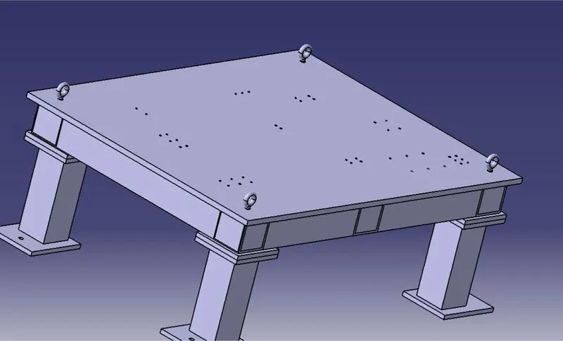
d) Only base plate or welded structure Depending upon the component size & weight of the total units you can decide whether you need a fabricated base or just a plate. Mostly fabricated bases are used made of square or rectangular tubes with the plate.
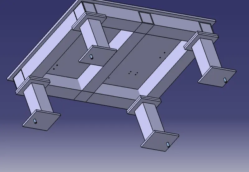
e) Most of the OEM makes 4 dowel holes at 4 corners & put small aluminum plate marking X, Y & Z coordinates of dowel holes. If the base length is too long few OEM’s follow the methodology of having holes at 500 mm distance.
f) The best unit of the fixture must be strong enough so that deflection of the fixture is as minimum as possible. This deflection of a fixture is caused because of forces of welding, clamping of the workpiece.
g) The base unit of the fixture should have the mass to prevent vibration & chatter.
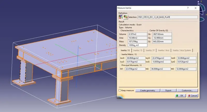
h) The base unit may be built from simple sections so that other units may be fastened with screw or welded necessary. Those parts of the fixture that remain permanently with the fixture may be welded. Those parts that need frequent changing may be held with screws.
i) The base unit should be parallel to the floor, to adjust this there should be the provision of the height adjusting mechanism.
3D Finish
3D finish is a process where the design is being completely finished & to be ready for final simulation & 2D detailing. The following points are taken into consideration while finishing the design
Hole concentricity & hole sizes
All parts holes concentricity & holes sizes are checked for easy assembly while finishing the parts.
Machining area.
The machining area in every part should be defined & the machining area should be highlighted by using standard color code. Machining is to be done on parts to properly mount with mating parts. Machining only on desired faces reduces cost & saves time also machining increases the accuracy of dimension. So before going to simulation or detailing machining area should be defined.
Nominality
All units dimension should be maintained nominal to facilitate easy assembly of the unit.
Holes coloring standard
In 3D finish holes, coloring should be done because it helps to identify what type of hole it is? It depends on customer standards. The customer specifies colors
Hole coloring standards used in this project :
Dowel holes - Blue color.
Threaded holes – Yellow color.
C. bore or simple holes - Cyan green color.
Pneumatic lay-outing
The pneumatic layout is a collection of different pneumatic pipes which work as an inlet to the pneumatic cylinder. It should be done properly for proper functioning of the units.
Gaps checking:
The gaps between the different units were checked to ensure the proper individual working of different units.
Fasteners implementation
Fasteners should be implemented in all units as per the requirement & load on the part
Avoiding clash between different parts
A proper gap should be maintained between units to avoid the clash between the different units.
Mylar splitting as per panel profile
Mylar splitting as per panel profile should be confirmed while finishing the design.
Proper renaming of parts/ assemblies as per the standard
Proper renaming of parts & assemblies should be done while finishing the design hence we can identify each & every part easily with unique identification.
2D DETAILING
The fixture design after the 3D finishing process has to be done with 2D finishing before it is sent for manufacturing. All the dimensions of the fixture units and their child parts have to clearly mentioned in the drawing sheets. The detailing can be changed as per the requirement of the customer and company standards. GD&T must be used in order to reduce the cost of manufacturing. All the views must be clearly visible and provided with dimensions in the drawing sheets.
Key Sheet: A index of units and their placements on the tool base
Layout Sheet: A detailed drawing of individual units to include all of their components
DOCUMENTATION:
A bill of materials (BOM) is an extensive list of components, and instructions required to construct, manufacture, or repair a product or service. A bill of materials usually appears in a hierarchical format, with the highest level displaying the finished product and the bottom level showing individual components and materials.
A bill of materials (BOM) is a centralized source of information containing a list of items used to manufacture a product and instructions on how to do so.
Often shown in a hierarchical way, a bill of materials (BOM) lists the finished product at the top, down to individual components and materials.
Bills of materials (BOMs) can be presented as an explosion display or an implosion display.
The two main types of bills of materials (BOMs) are manufacturing bills of materials (BOMs) and engineering bills of materials (BOMs).
It also has the following benefits:
Calculate total costs of manufacturing a product
Plan for raw materials, workstations, and employees
Maintain consistent standards for a product across the factory.
Bill of Parts(BOP): A bill of parts is the list of standard items that are bought out from the supplier like pneumatic cylinders, stoppers, etc.
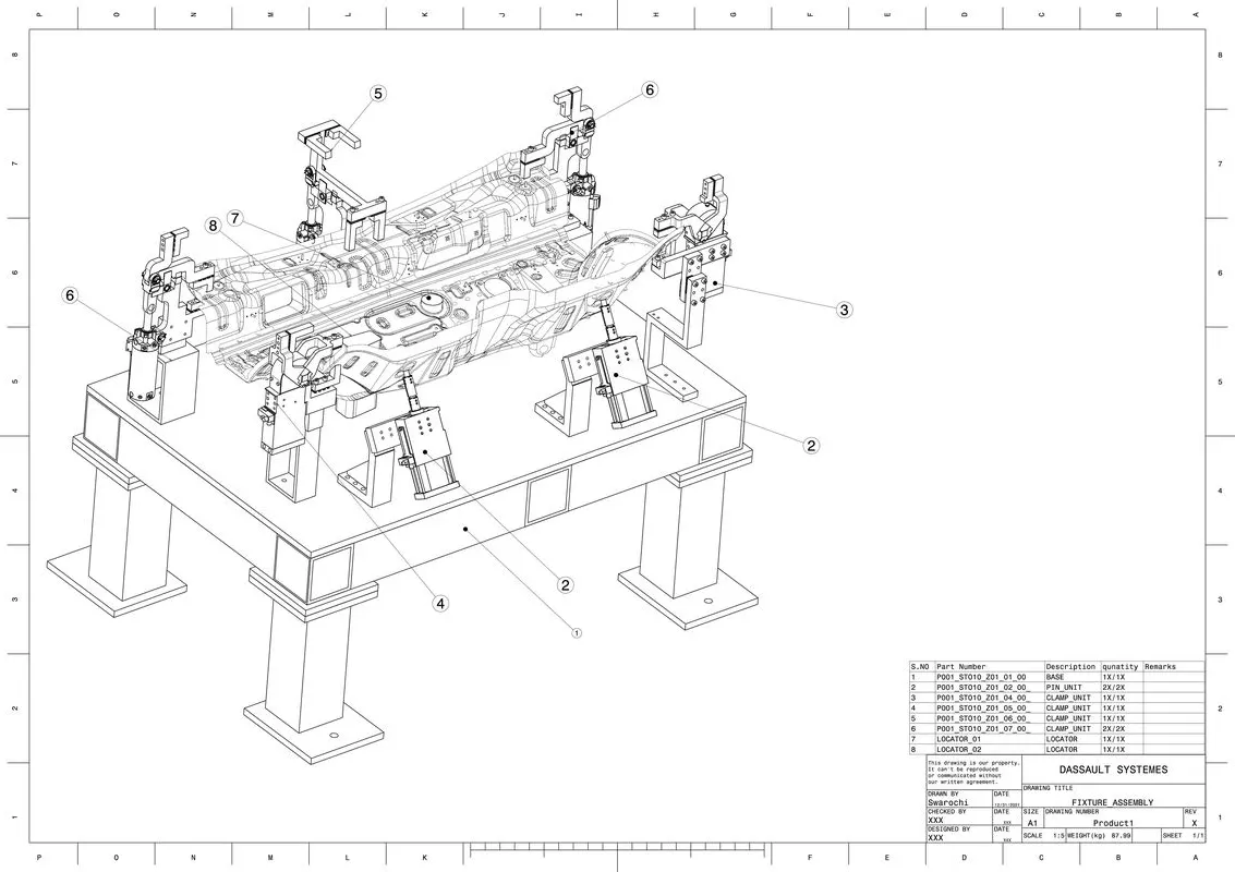
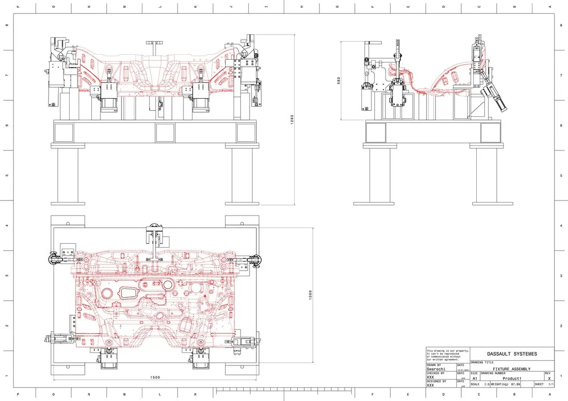
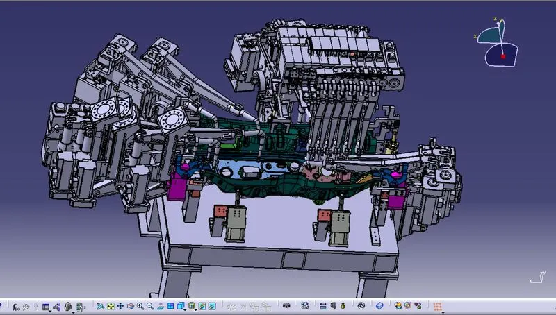
AIM:
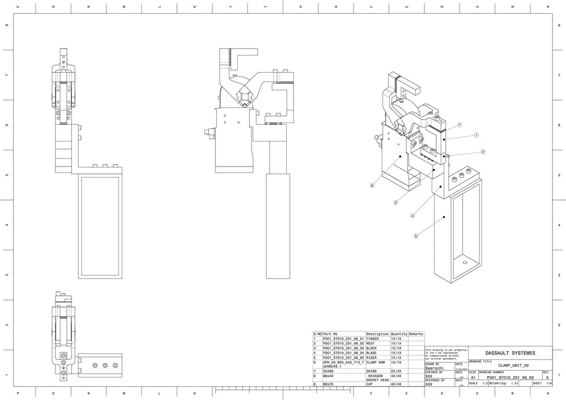
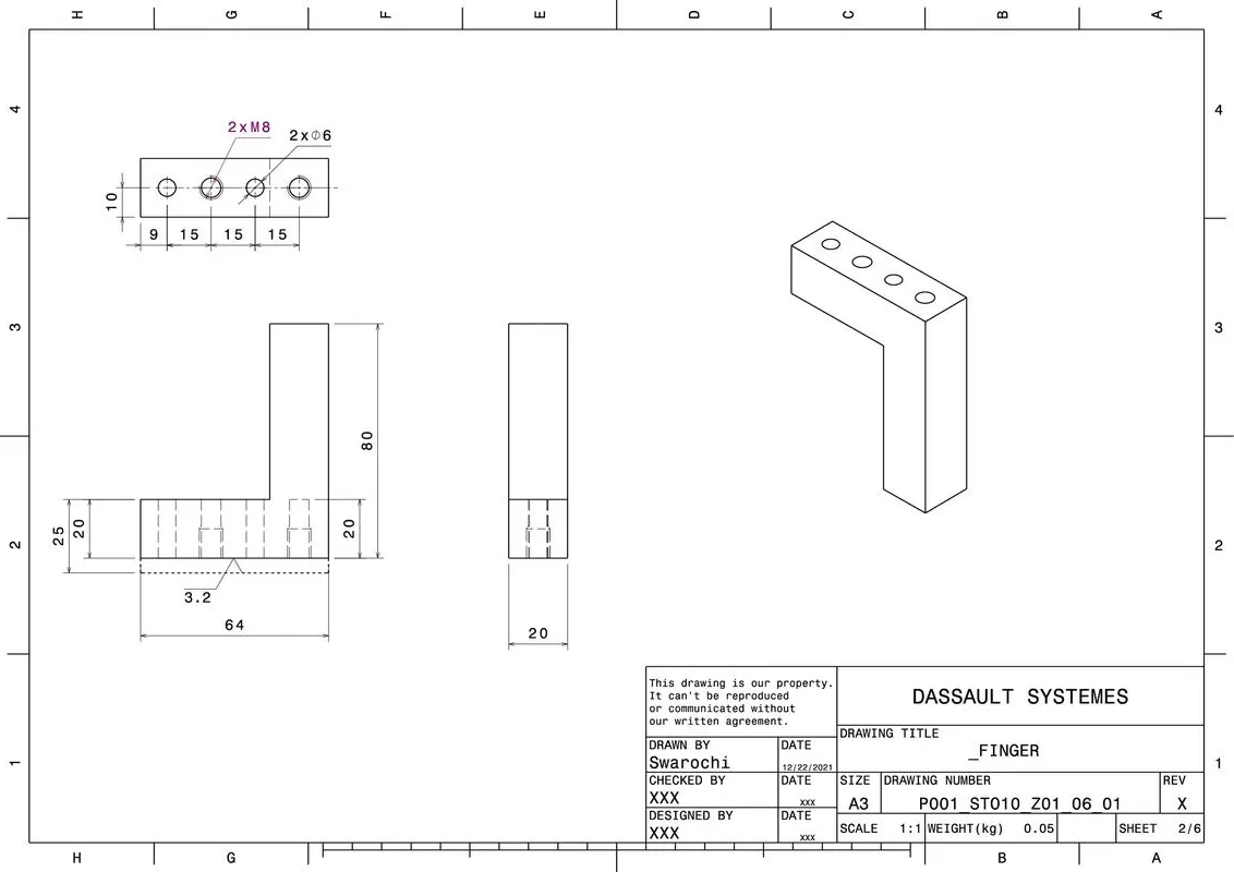
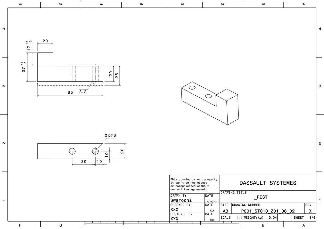
1. Create 2D Drawing for each Clamp Unit and Pin Unit with all child parts and also create Child pard drawing for the same for the Fixture assembly
2D Detailing:
P001_ST010_Z01_05_00_CLAMP_UNIT
P001_ST010_Z01_06_00_CLAMP_UNIT_02
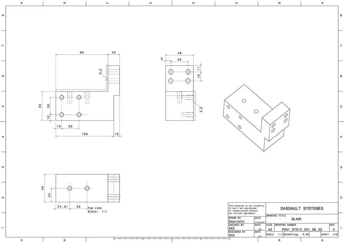
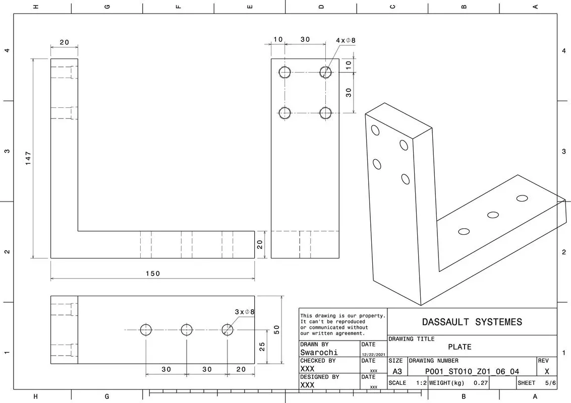
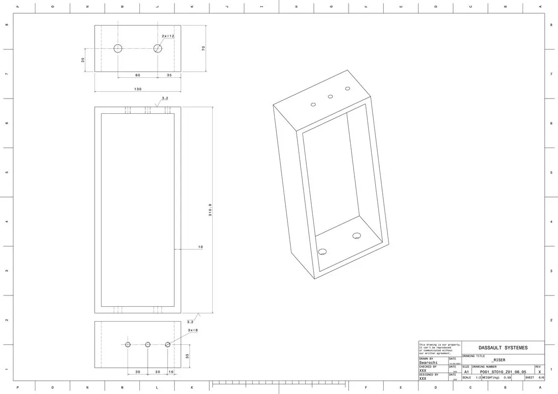
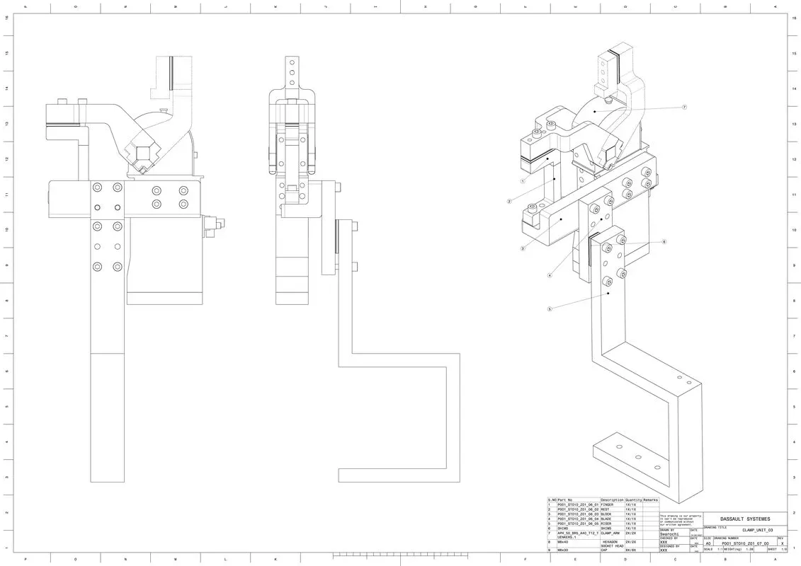
P001_ST010_Z01_07_00_CLAMP_UNIT_03
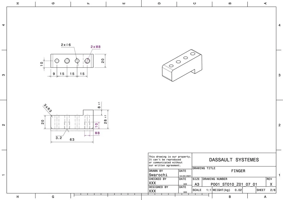
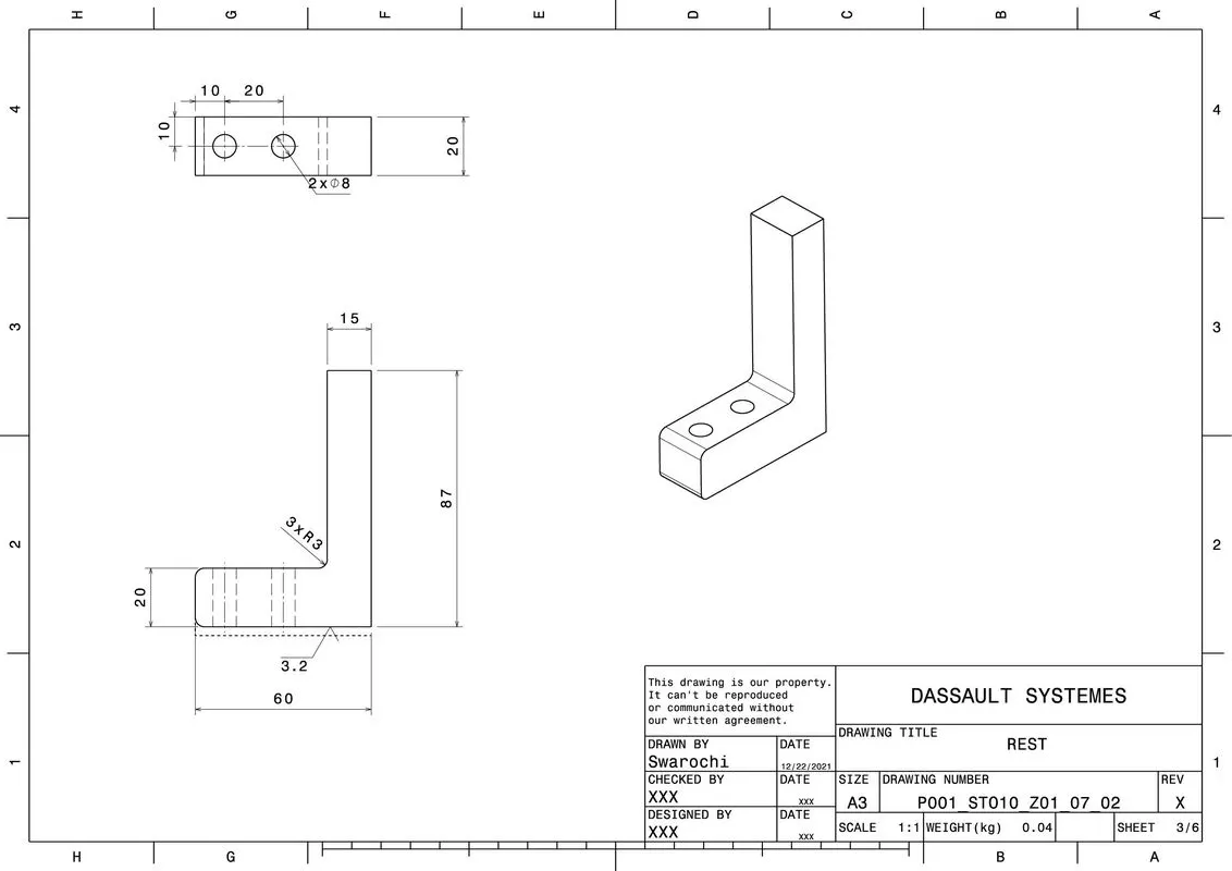
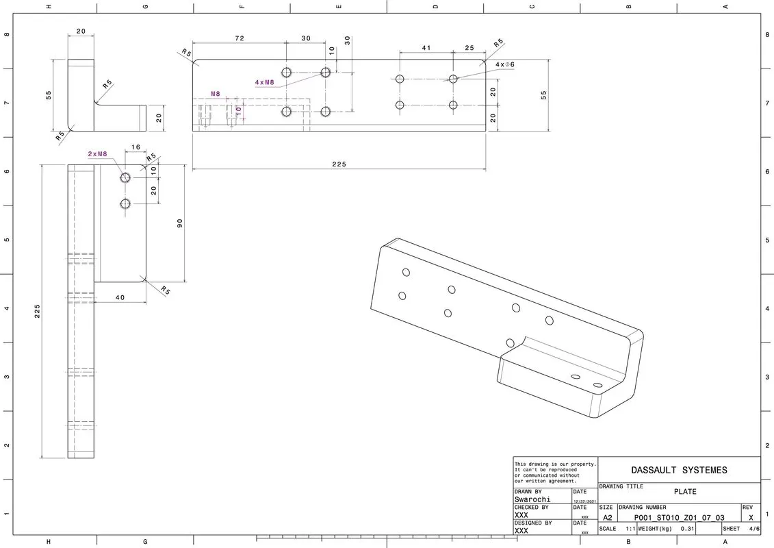
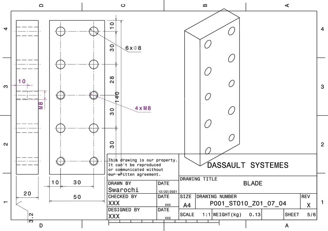
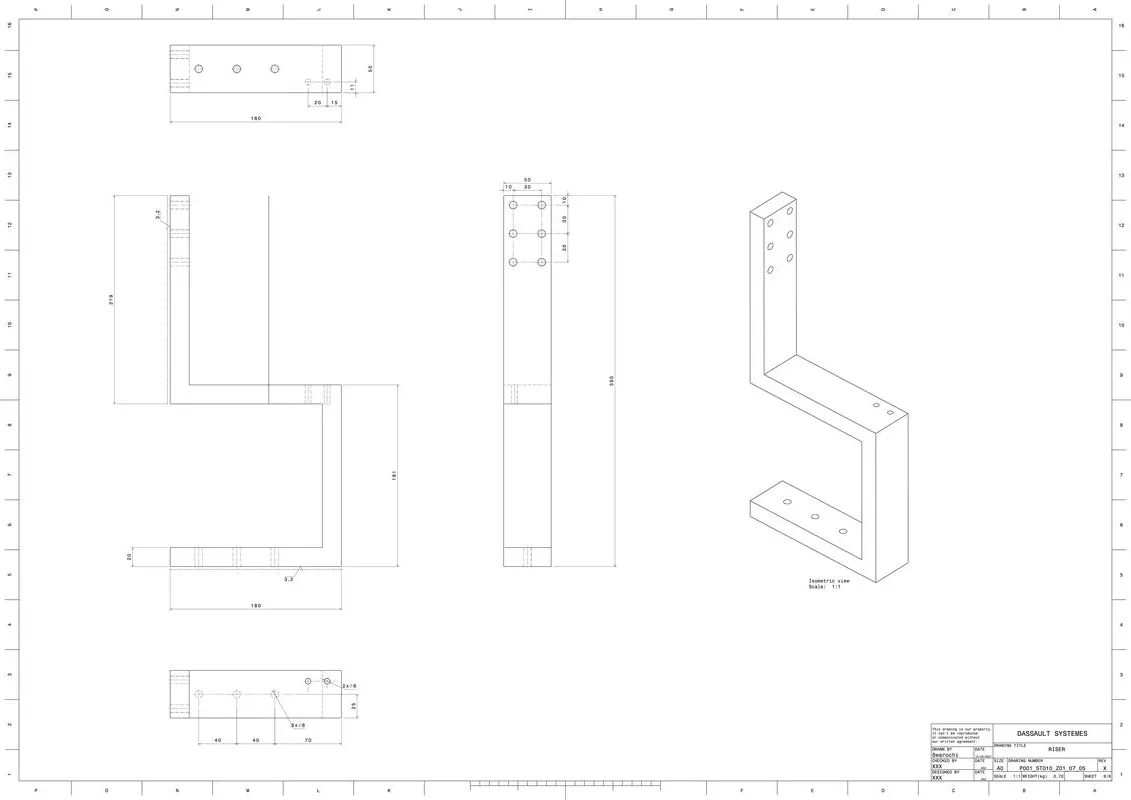
P001_ST010_Z01_08_00_SWIVEL_CYLINDER_CLAMP_UNIT_01
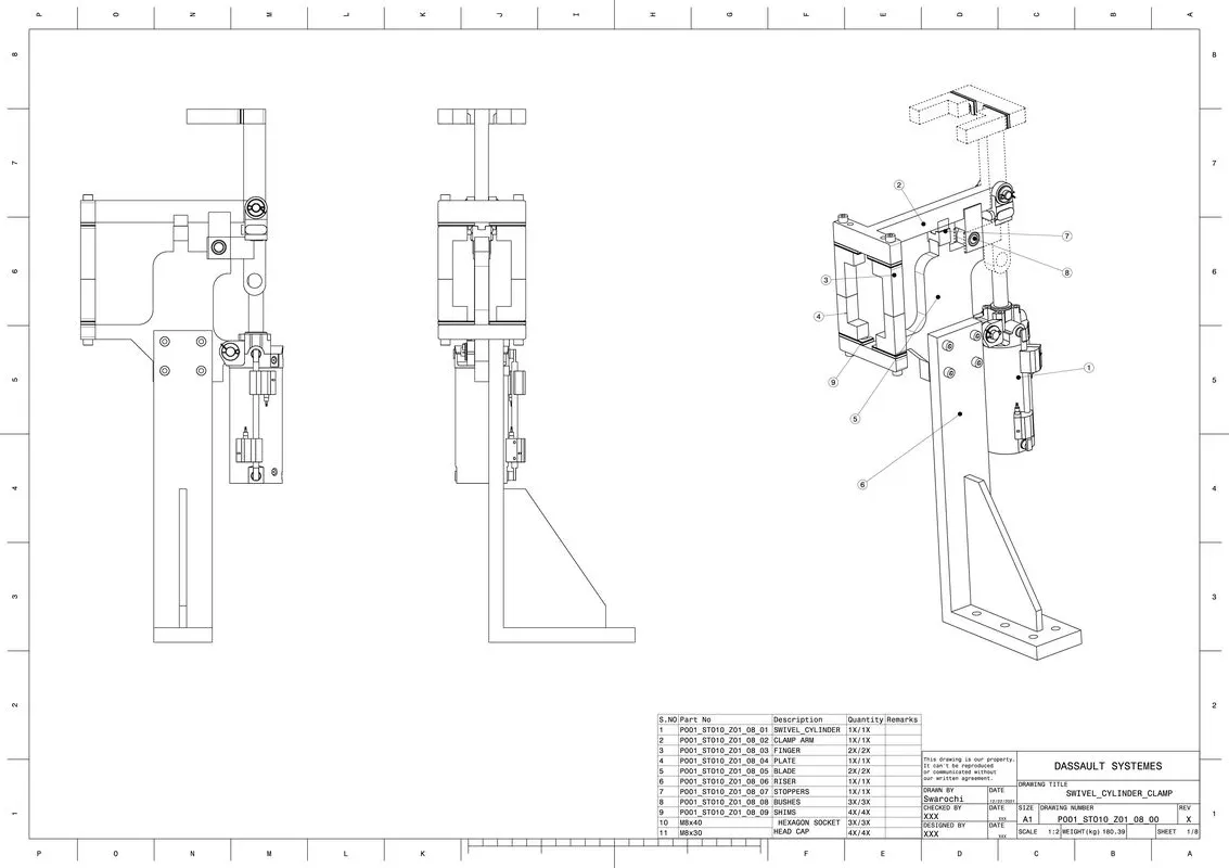
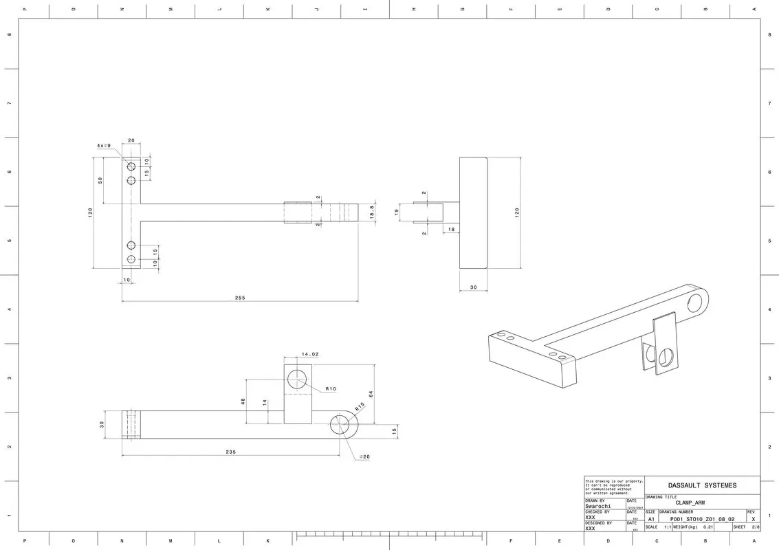
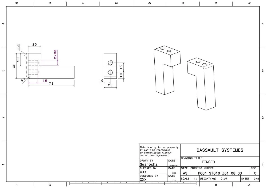
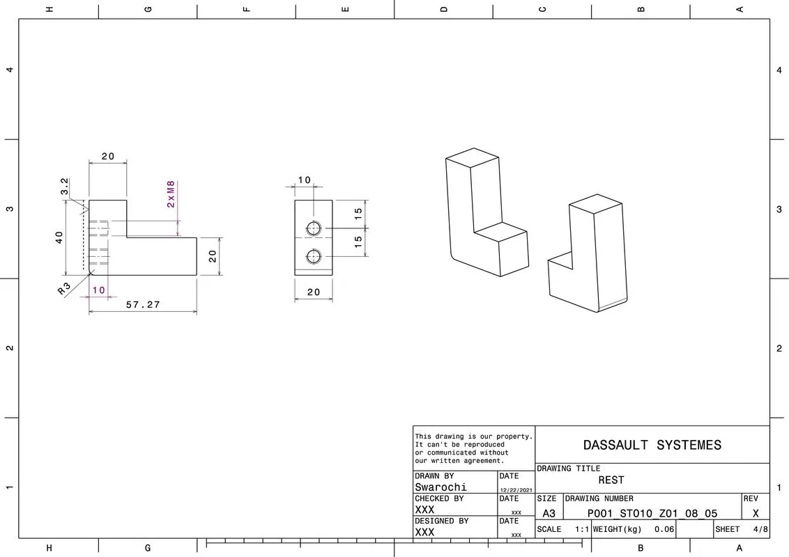
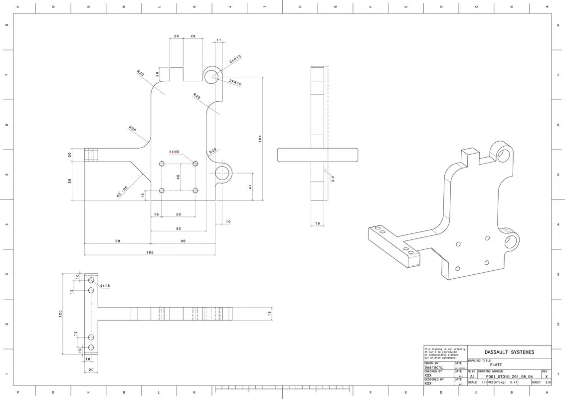
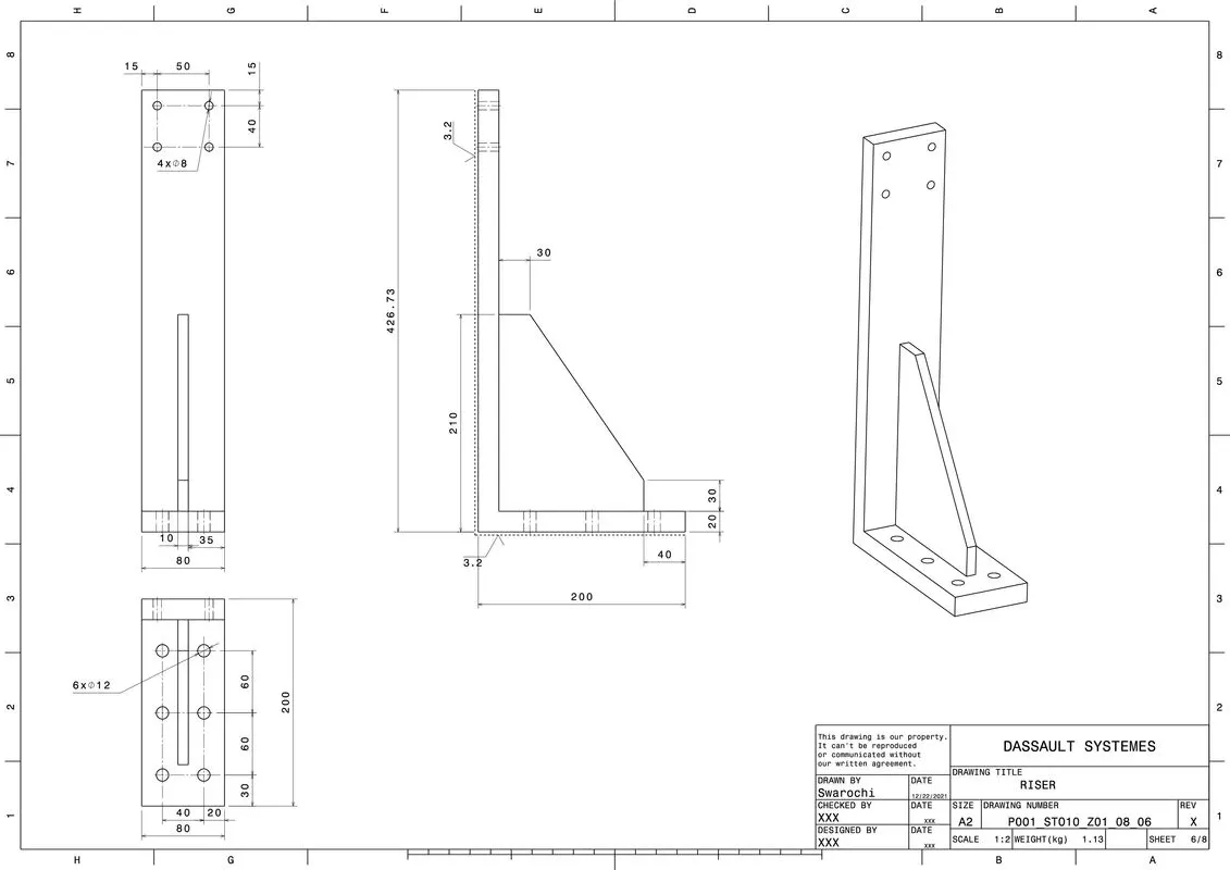
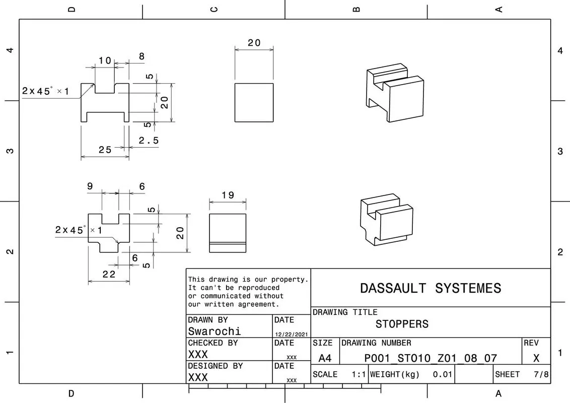
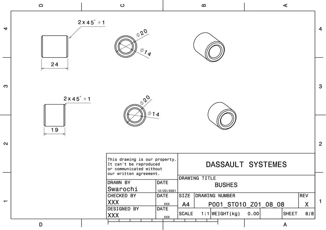
P001_ST010_Z01_09_00_SWIVEL_CYLINDER_CLAMP_UNIT_02
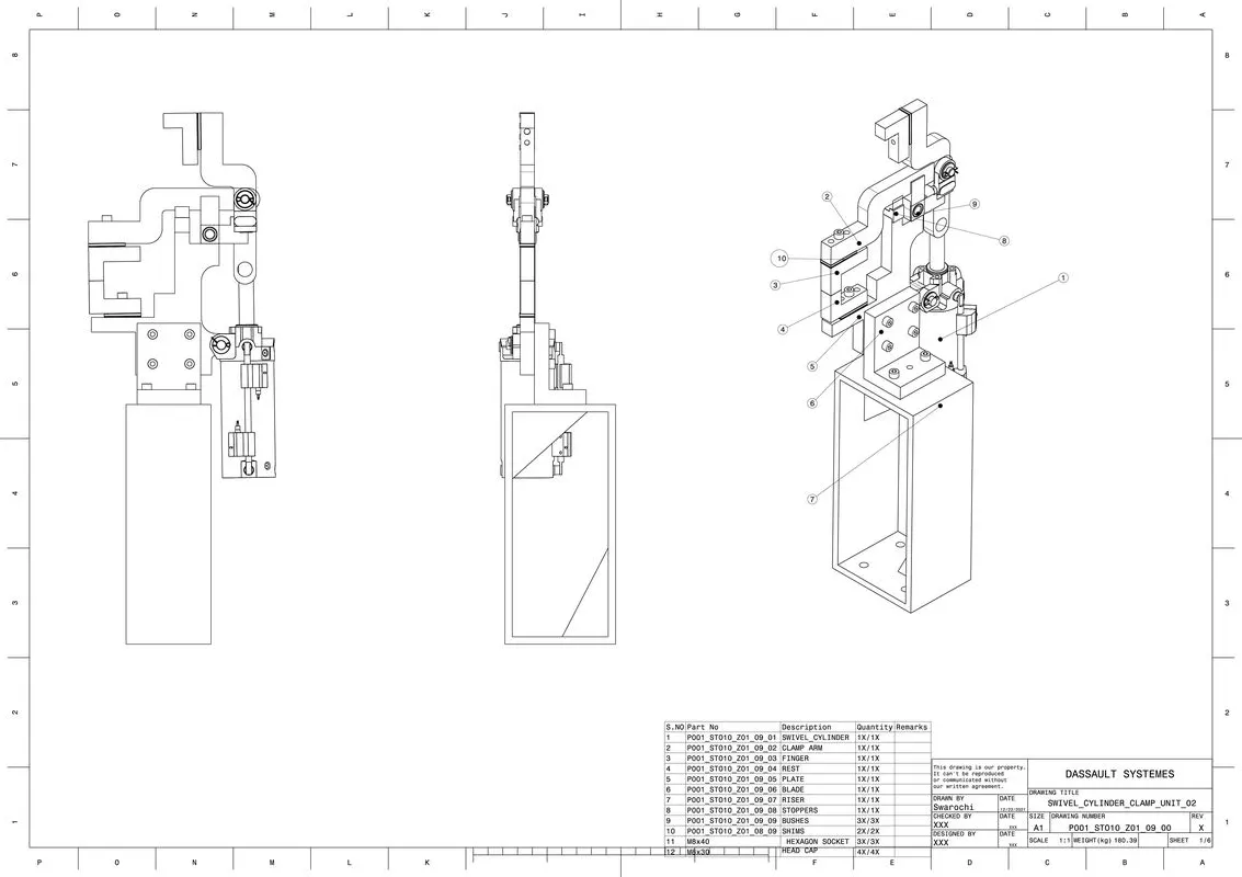
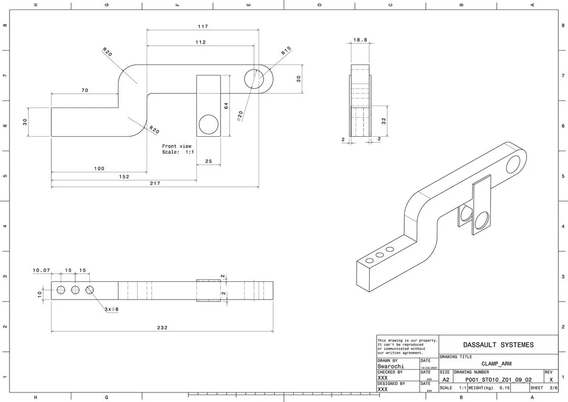
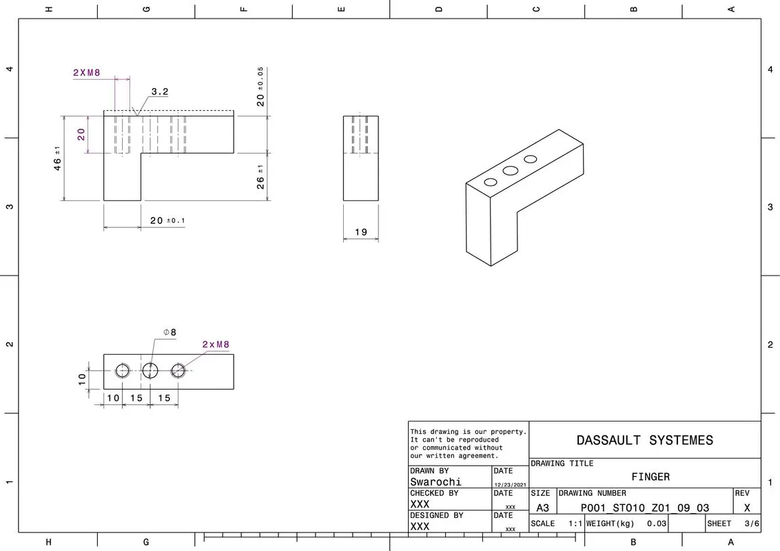
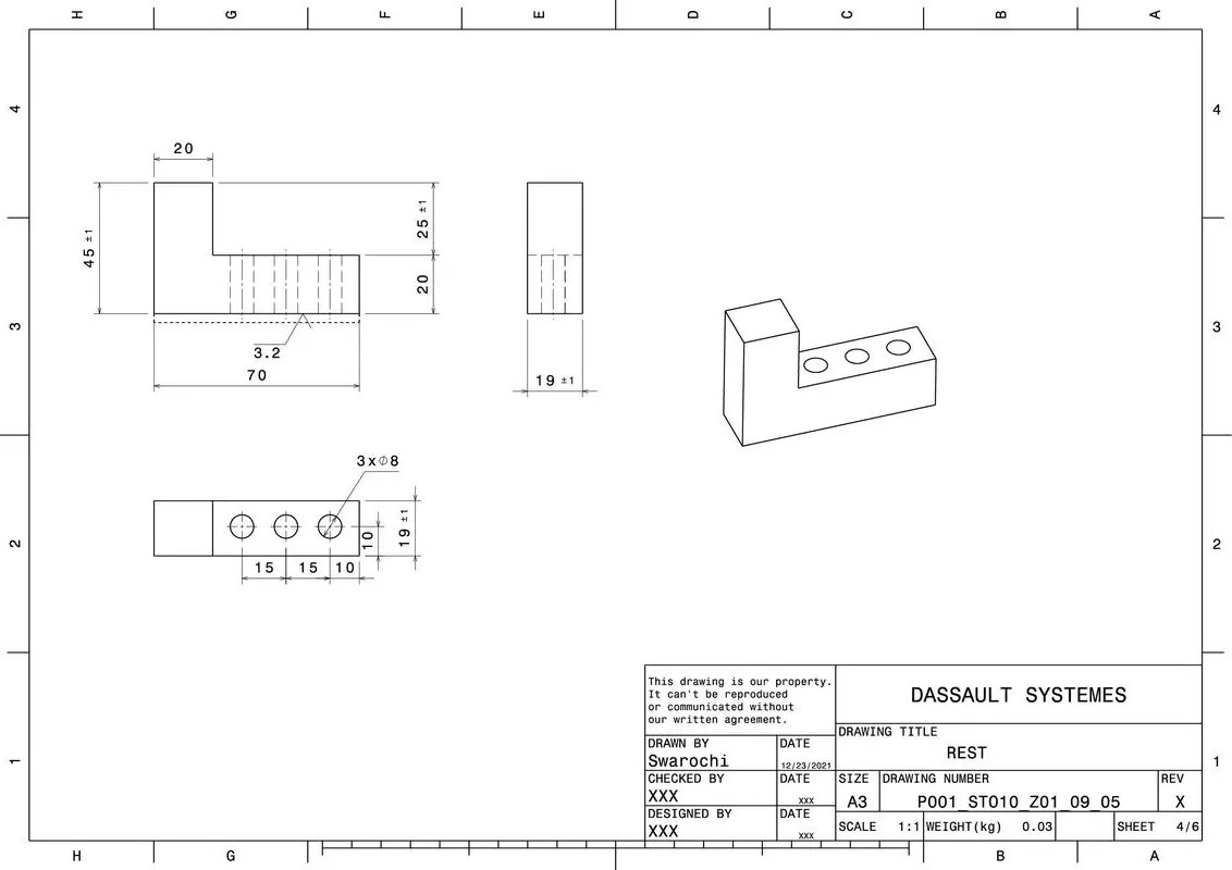
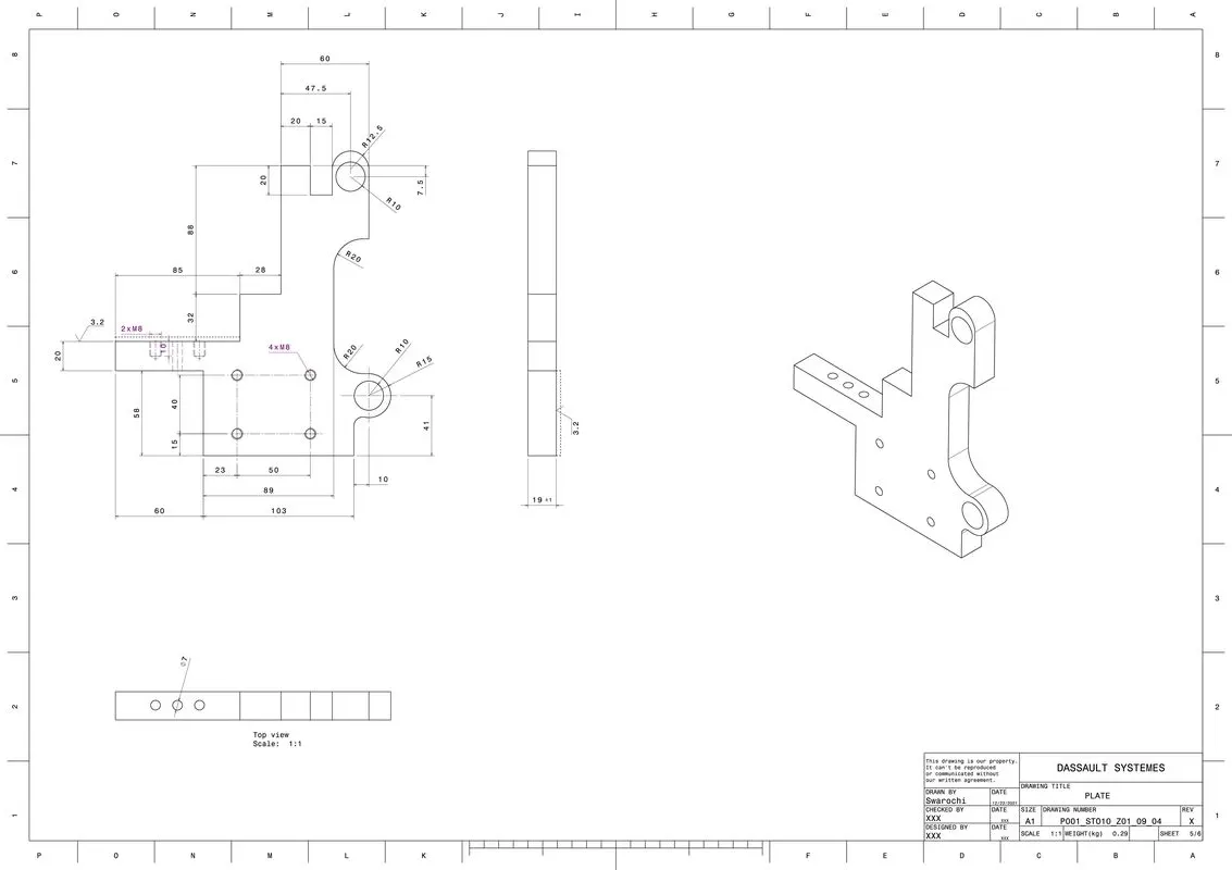
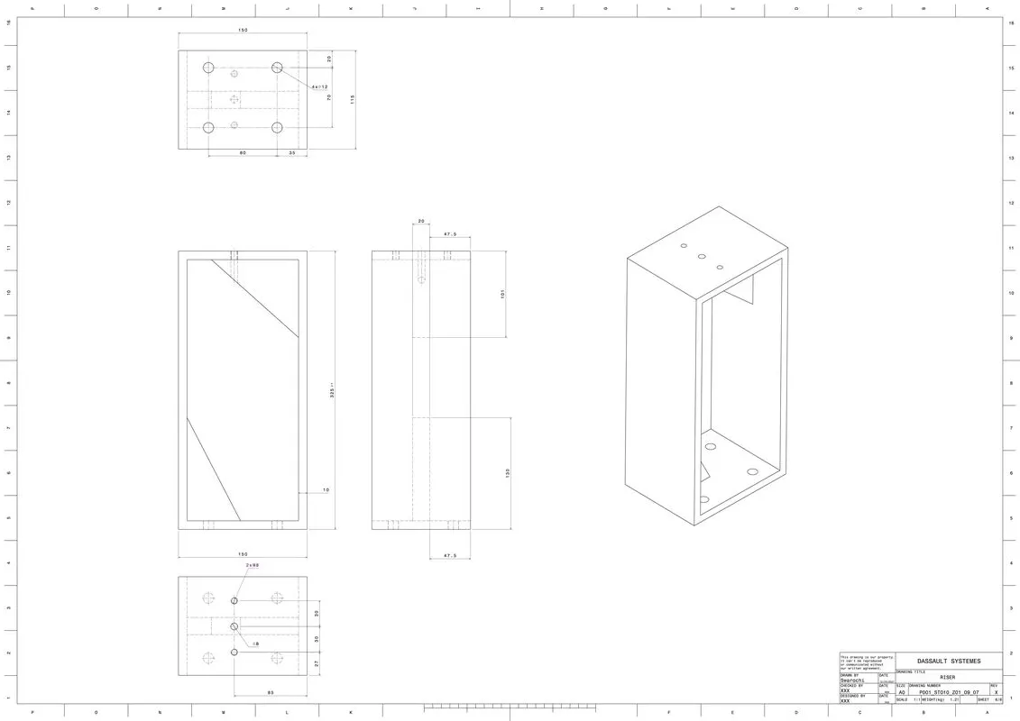
P001_ST010_Z01_10_00_SWIVEL_CYLINDER_CLAMP_UNIT_03
Stoppers and Bushes are taken form the previous clamp unit
P001_ST010_Z01_03_00_RECTRACTABLE_CYLINDER
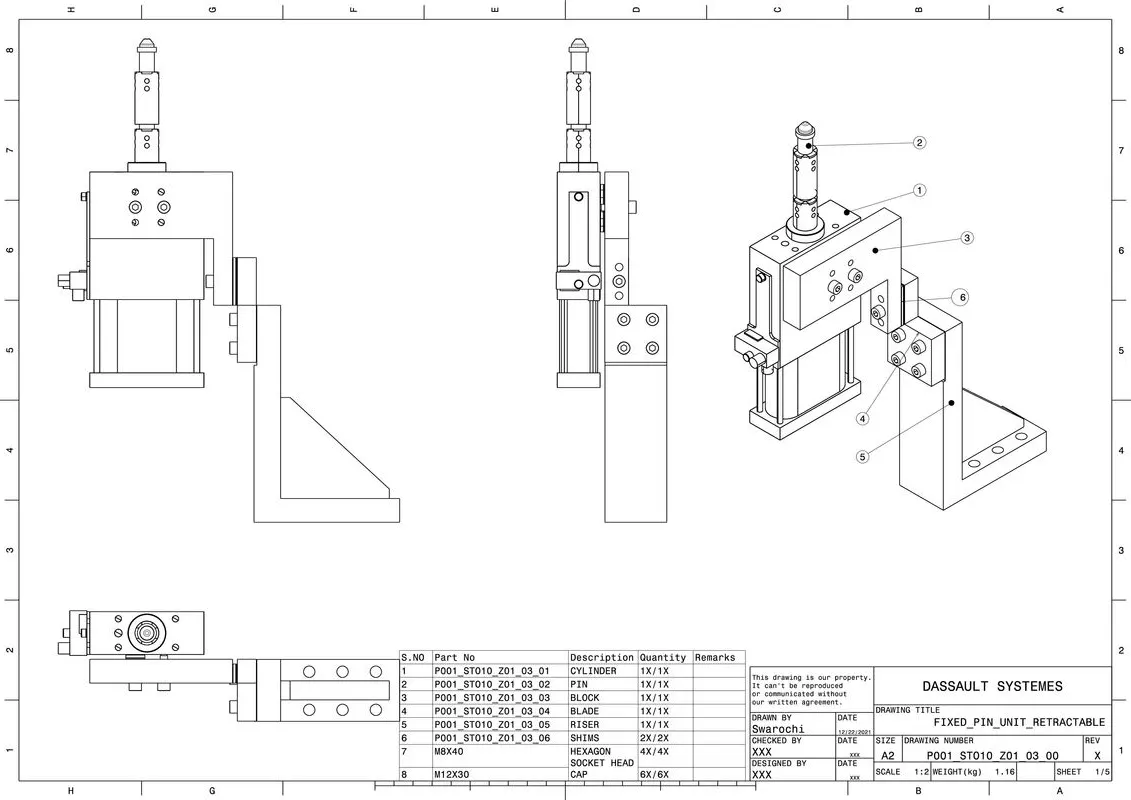
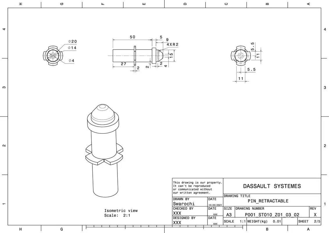
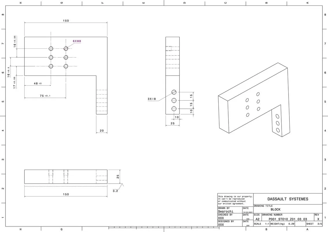
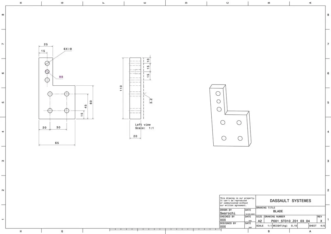
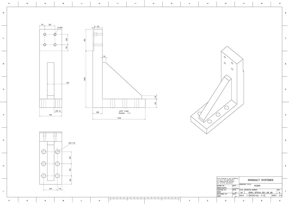
CONCLUSION
Modeled rough concept of Fixture design with reference to all the inputs provided for the given Car panel. CompleteD 3D finish work. CompleteD 2D finish with Output documentation.BOM and BOP are submitted in excel format