Project 2
WIRING HARNESS PROJECT-2
Aim:
To Route the Wiring harness on the Given car body and Prepare a flattened view drawing in CATIA V5. Application of all Packaging rules, Industry best practices studied in this course shall be demonstrated in design. Apply Protection coverings as required.
Available connector 3D data can be used, or you can download the connectors from www.te.com
Prepare & Submit all necessary reports like clearance, Clipping/Clamping selection, Harness fixing requirements, Harness continuity, and Assumptions if any along with CATIA 3D data.
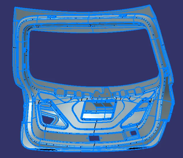
Backdoor Given CAD Data file:
The Below Main important packaging rules and best practices to be considered during wire harness routing and placing of the clips and clamps are as follows –
- Distance between two clamps on a straight branch should be minimum of 200mm.
- The minimum branch length should be 50mm.
- Minimum distance between clip and nearest branching point should be 25mm.
- The minimum distance between two straight connection points should be 200mm.
- The minimum distance between two breakout points should be 50mm.
- To limit the number of branches from a single branch point to 4.
- Avoid routing wiring harness near the exhaust manifold and its components and also from other unshielded heat sources. If re routing is not possible then maintain a minimum distance of 200mm.
- Try to avoid use of too many metal brackets on engine. Try to use the available threaded bosses on engine or demand for it.
- Enough clamps shall be provided to ensure positive clearance with surroundings and safety of wiring harness.
- P - Clamps, Fir tree clips and other clips can be added to the Geometric bundle as they are electrically defined and are part of the Wire harness routing and should be provided with the Wire bundle package.
- Enough slack should be provided to the wiring harness which help not to get damaged during the Engine rocking or starting condition.
- The wire harness routing should be done in such a way that it is easy in manufacturing and serviceability.
- The wire routing should be done keeping in mind the cost effectiveness of the bundle package.
- To avoid the harness routing and clipping in blind zones of the operator during the assembly and the service.
- To provide proper slack at end connectors so that there will be no tension on the wire bundle.
- To avoid sharp edges on the sheet metal parts and if it is not possible then provide protection parts to prevent damage of the wire bundle.
- To provide separate branch points for separate connectors to ensure Poka-Yoke.
Harness Routing and Packaging:
- The above image is the Backdoor of a car for which a Wiring Harness has to be designed
- A wiring harness will be done for the taillights and the no plate lights
- There are two 2-pin Taillight connectors and two 2-pin for the no plate lights and a 12-pin Inline connector
- The inline connector that will connect it to the Main Harness
- The bend ratio should be 1.4 for all bundle segments.
To Define the Connectors
Here, according to the requirement, we are using
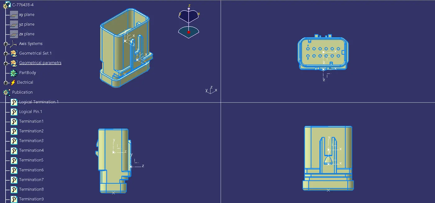
- ‘C-776438’ Which is a 12 Pole connector is used as an inline Connector
2. 'C-DT06-2S' which is a 2-pole connector for Number Plate Light and Tail lights.
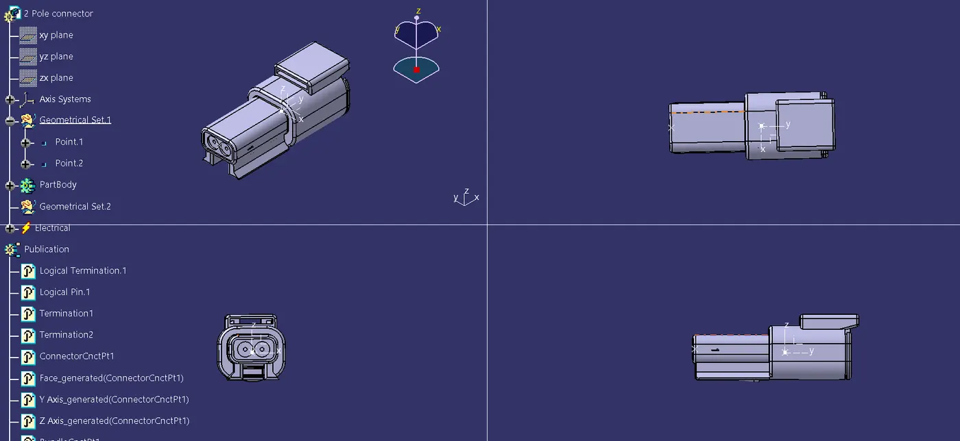
This CAD data was obtained from te.com. To electrically define a connector, we must first define the geometrical parameters such as the bundle connection point and connector connection point in the Electrical Part Design workbench for the downloaded connector.
For Support, we use Fur tree Clips:
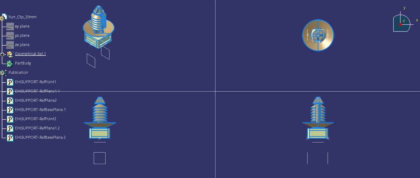
We need to mount the fur tree clips on the Backdoor to provide support as well as act as a guiding channel, so we must first define it electrically with geometrical parameters, entry, and exit points on both the left and right sides of the clips, as shown in the figure below.
Mounting the all Fur tree clips and connectors required locations attached the images below:
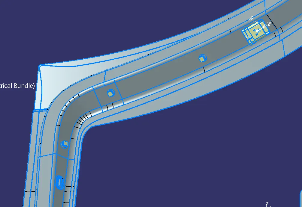
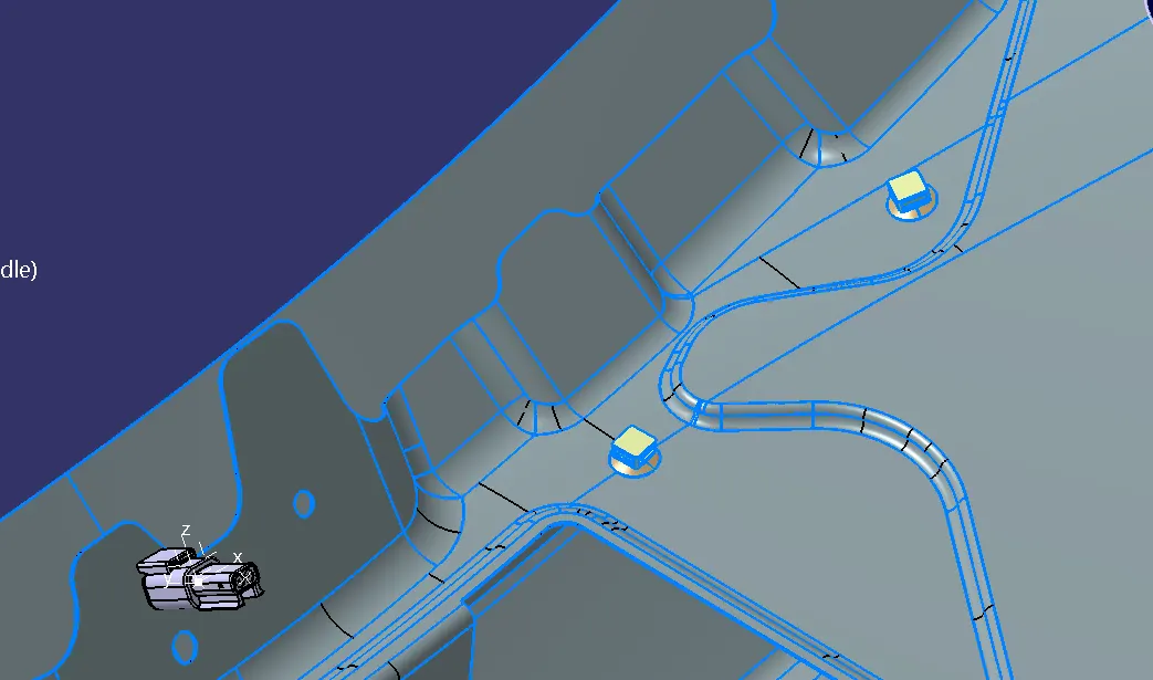
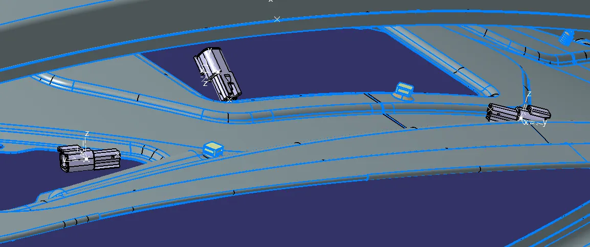
For the placement of the fur tree clips and the Connectors we used various commands such as manipulation, snap, smart move, compass, and so on.
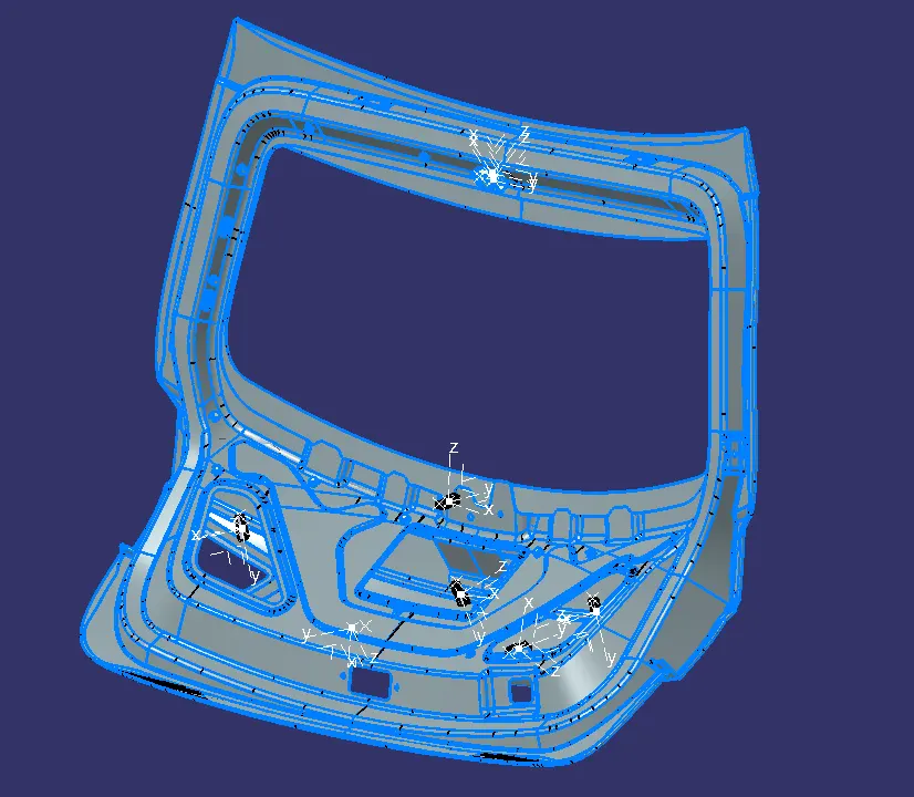
The entire assembly is ready for routing
Mounted are all connectors, fur tree clips, and Interconnection connector
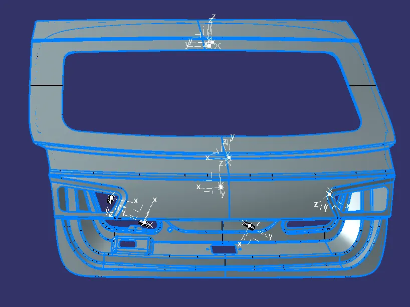
Wiring Harness Bundle Routing:
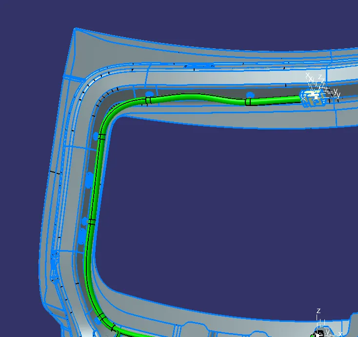
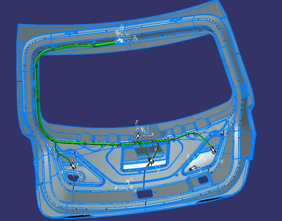
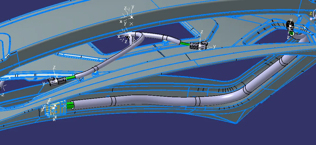
The bundle segment is routed from the interconnection connector to the fur tree clips and guided towards the 2 Pin connectors. while maintaining the Bend radius ratio of 1.4.
Adding Protective Coverings:
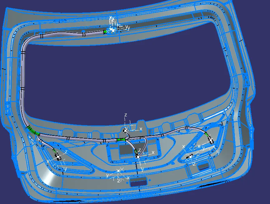
Add protective coverings on the wiring harness to protect wiring from high temperature . protective covering created by using define protection part command in the electrical part design workbench. Select part , and define the parameters as per the requirement.
The created corrugated tube can be added into the catalog by store device command and selecting the catalog file created for protective covering. then appropriate protective covering added to the bundle segments.
Here is the below figure, we have done with the whole wiring harness routing for the Backdoor. Now, we have to add protective coverings to all bundle segments.
Checking The Harness Bundle segment cointinuity:
We need to ensure that the entire bundle is fully connected.
Go to edit and then click on search command.
Go to advanced
Select workbench as electrical, type as bundle segment and attribute as Fully connected
The select result should be as TRUE or FALSE and the click search to see the connectivity analysis result
After result,
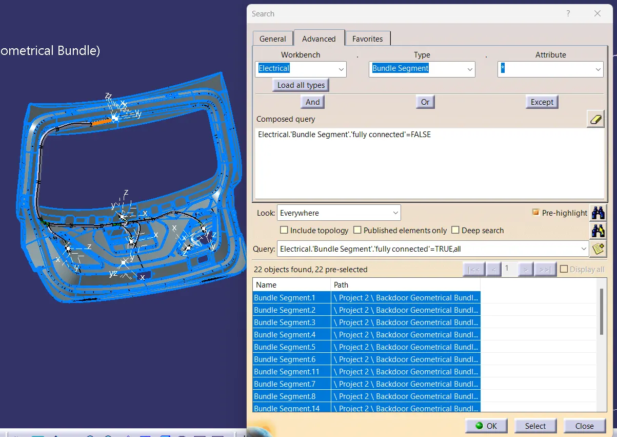
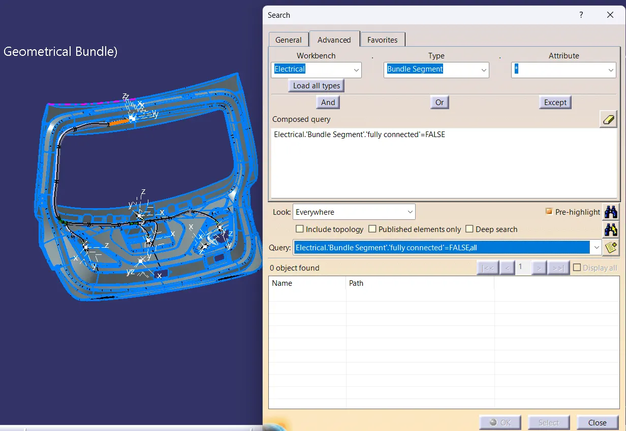
Selecting the "TRUE" option will show all the connected bundle segments while the selecting "FALSE" will show all the non-connected bundle segments.
For now, we will select "TRUE" and search for results. All the bundle segments are highlighted and found showing that all the bundle segments are electrically connected.
WIRING HARNESS FLATTENING:
In this step, we will use Catia V5's Electrical Harness Flattening workbench to create a flattened view. We should also ensure that the flattening file is saved in the same folder as the other harness assembly files.
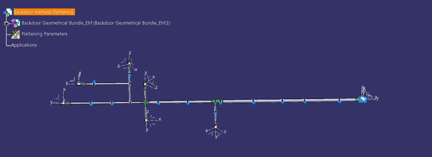
- The bundle assembly was extracted into a Back door wire Harness Flattening Product file, which was then flattened along the face of the interconnection connector.
- We developed a flattened view.
- we must rotate bundle segments connecting to the connectors using the 'Rotate' feature of the flattening workbench.
- It should be noted that the 'face' of the interconnection connector serves as the flattening plane, so we must rotate the bundle segments only along that plane.
- We used various features such as bend, rotate, and roll to streamline the harness for better representation.
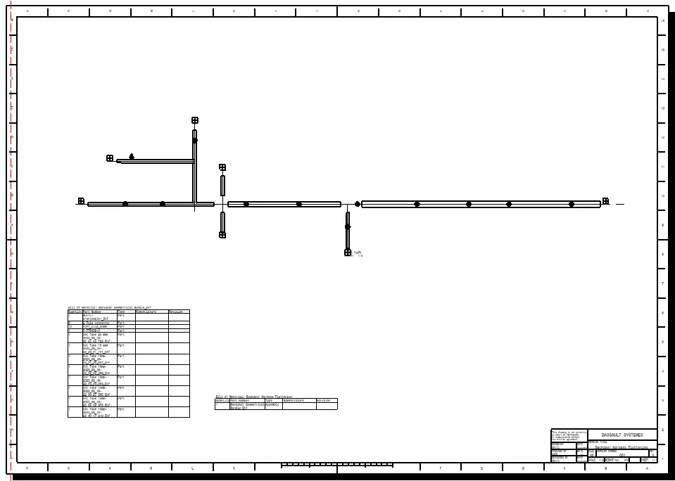
The flattened view's final representation.
Creating a flattened view drawing for the wiring harness assembly:
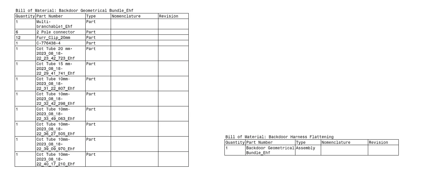
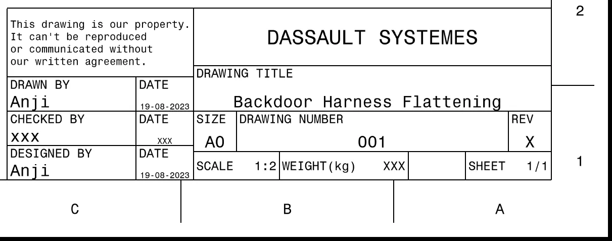
In the figure above, we're creating a new drawing file and defining all of the required drawing parameters. The front view of the Backdoor wire Harness Flattening Product file must be inserted into the Drawing file. As shown in the preceding figure, we must define drawing properties. It should be noted that the 3D wireframe is always ON in the 'Dress up settings. If this option is not enabled, the bundle segments will not be visible in the drawing view. the Backdoor wire Harness Flattens view's final Drawing view.
Conclusion:
Routing of the wiring harness for the car tail gate assembly has done and prepared flatten-view drawing in Catia V5. Applied all the packaging rules while routing the wiring harness, implemented industry best practices in the harness design. Also, provided details like clearance, clipping selection, harness fixing requirements, harness continuity in order to design the harness.