Project 2
REPORT:
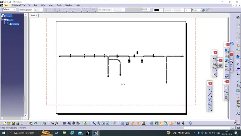
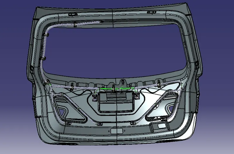
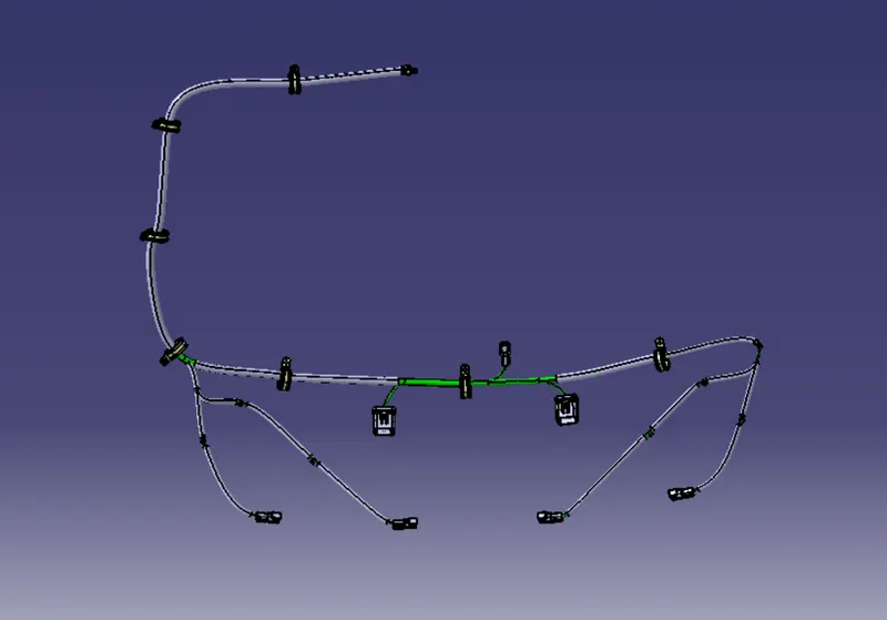
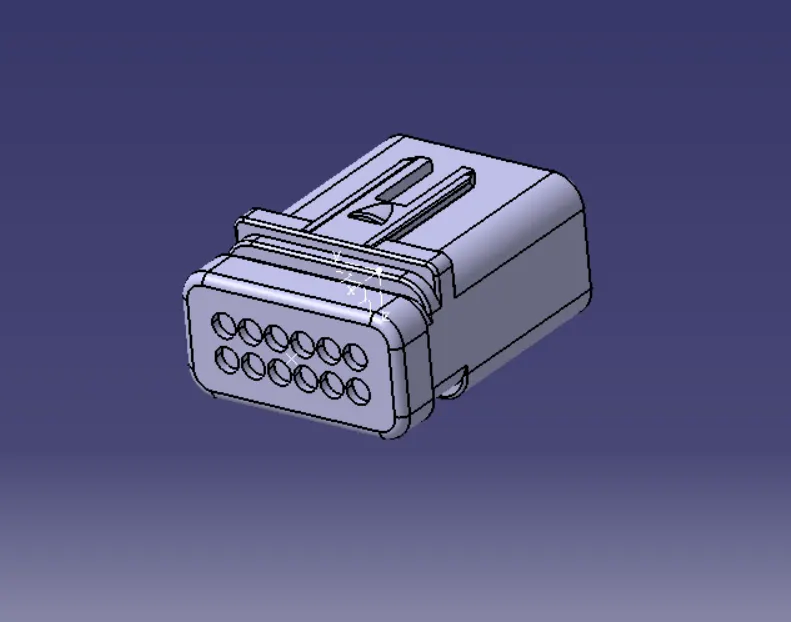
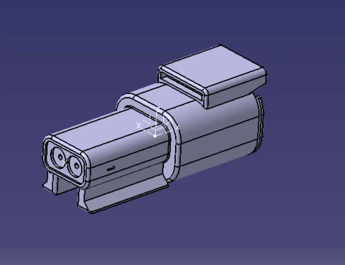
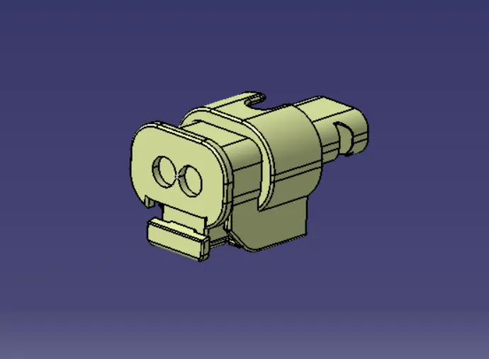
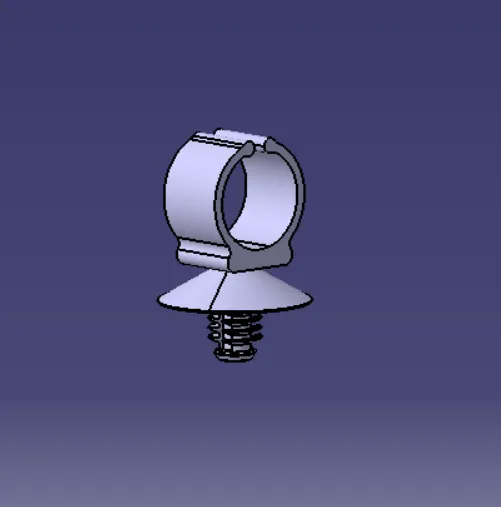
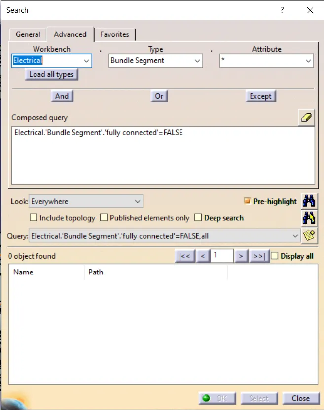
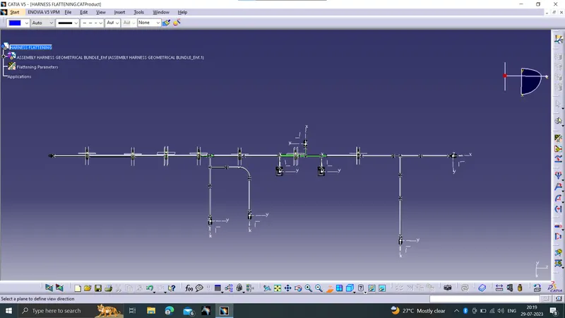
To route the wiring harness on the given car body. the given file is converted into catpat in catia v5 . first the back door is visualy checked for the connector area. after that required connectors are downloaded from te.com website . after that the connectors are opened in the part workbench for giving the parametres for the connection. after giving the parametres the connectores are opened in the eletrical work bench. the connectors are defined as electrical component. after that need the fixing components . required clips and clamps are downloaded from the te.com. after that those are cheked for the compatability. after that the clips and clamps are opend in the part workbench for giving the parametres. after that the connectors are opened int the eletrical workbench for defining it as eletrical components. after that created a new prodcuct file and added all the required connectors,clips and clamps into that product file. and named as geometrical bundle. and created new product file and added the back door file and geometrical bundle file into it. after that by using the manipulation feature and using compass the connectors clips and clamps are placed inthe required position. after that the geometrical bundle is converted into eletrical file in the eletrical harnness installation workbench. and started routing. the routing is done as per the requirements and proper clearance is given at the edges by giving proper slack to it.after completing the routing the routing was checked for the connectivity . this is done by using the search feature checked wheather the connection is fully connected . checked with the both assumptions true or false. the pictures are shown below. after that the routing is to be flattened for that the new product file is ccreated and opend it in the harness flatten workbench . first the parametres are given as per the requirement. and the routing geometrical bundle is extracted by using the extract option. after that by using the flatten feature flattened the routing. by using various command like roll, rotate ,bend the routing is fixed properly. images are shown below. after completing that the routing is taken to the drawing workbench for creating the 2d drawing ,the images are shown below.
back door
routing
connectors used
clips and clamps
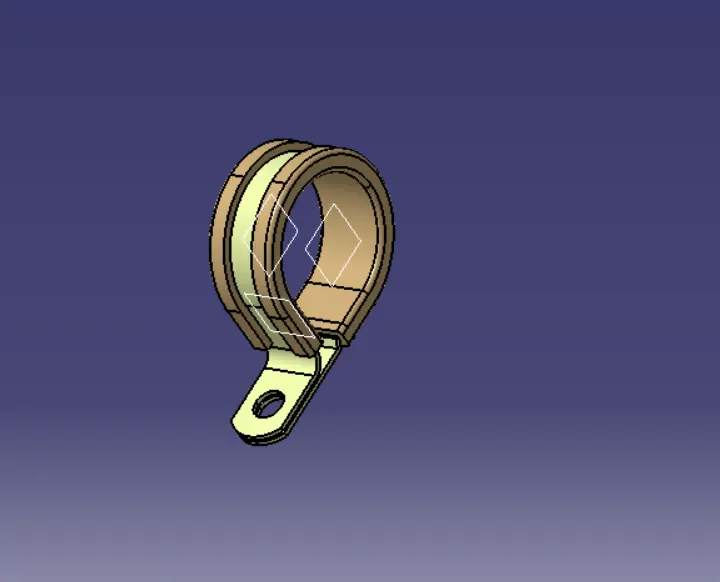
connection continuity
flatten routing
drawing