Project 2- Warehouse Building located in Chennai and simply supported gantry girder to carry electric overhead travelling crane.
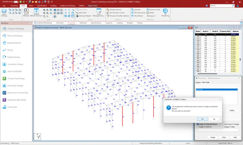
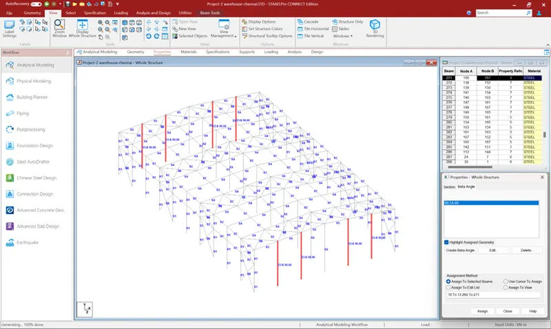
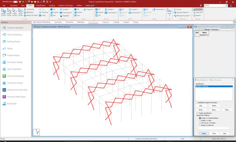
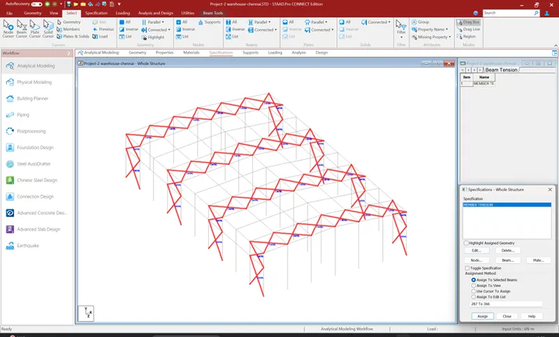
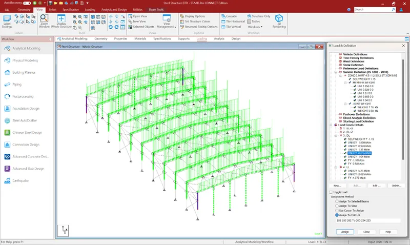
1. Design a Warehouse Building located in Chennai using STAAD Pro Connect Edition. The specification must be as follows:
|
Width |
30m |
|
Length |
50m |
|
Eave Height |
9m |
|
Bay spacing |
6m |
|
Soil type |
Medium |
|
Safe Bearing Capacity |
200 kN/m2 |
|
Roof slope |
1 in 12 |
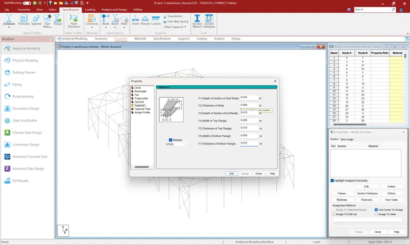
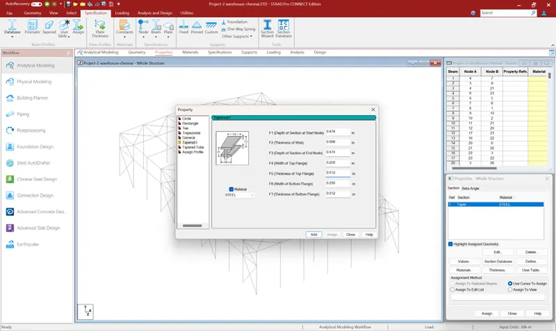
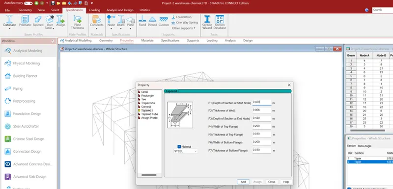
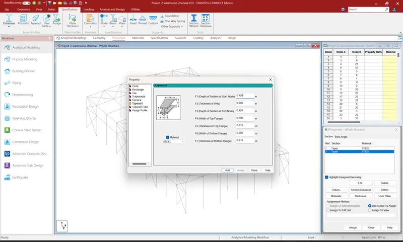
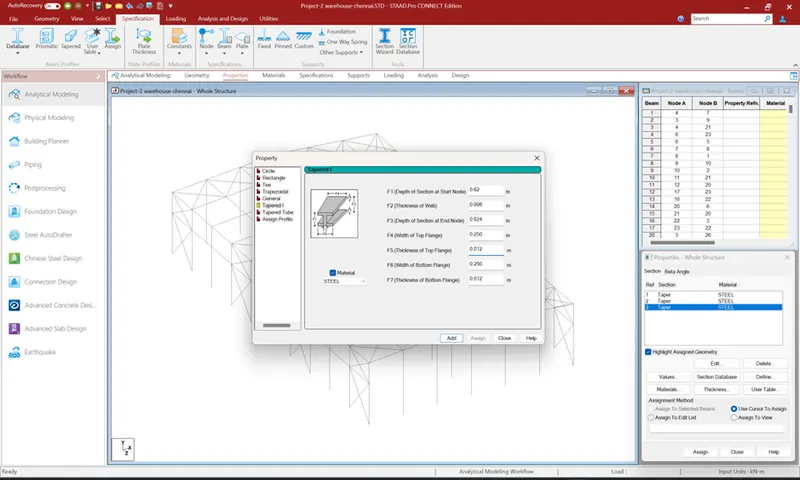
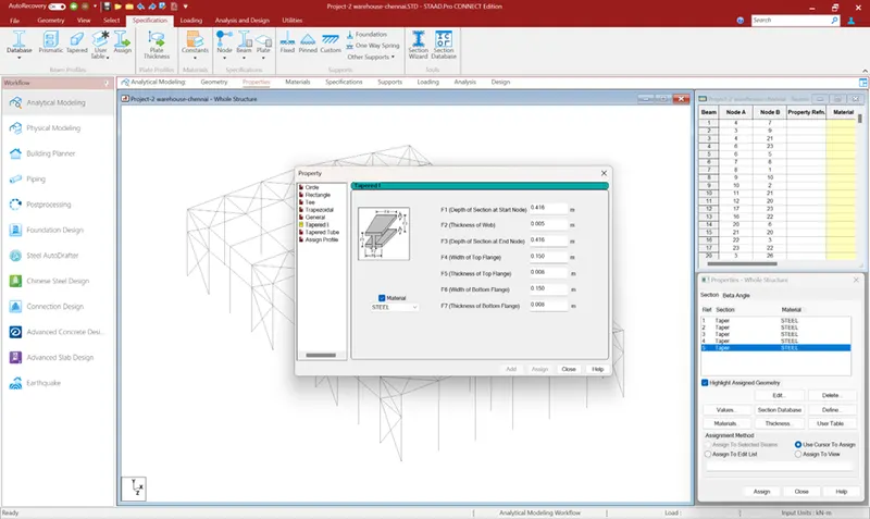
Assume suitable sections for structural elements. Follow IS800:2007, IS1893 and IS 875
- Prepare a Design Basis Report for the project
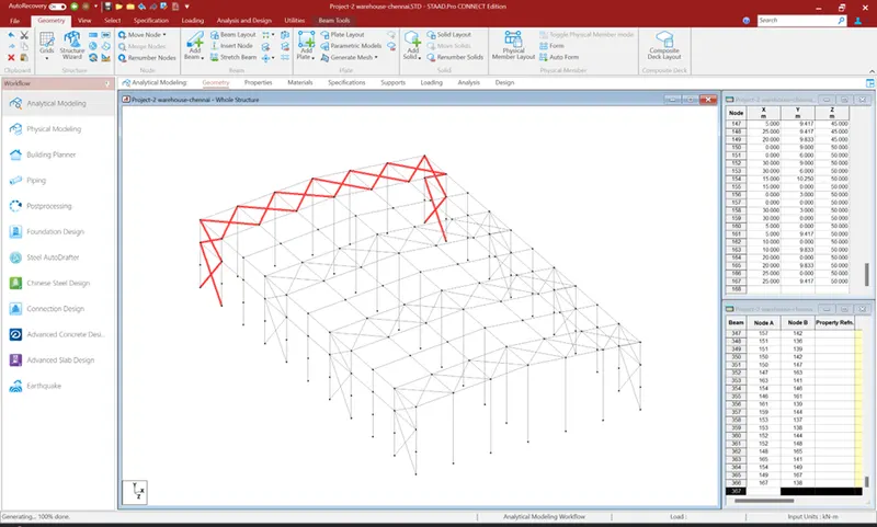
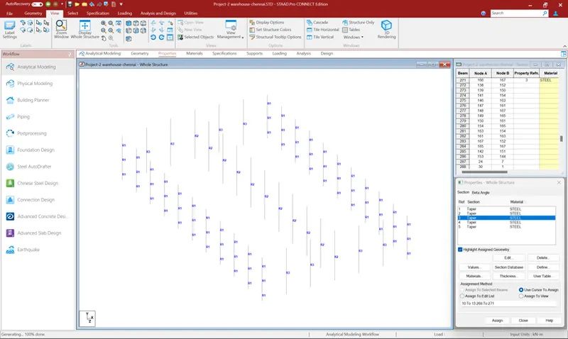
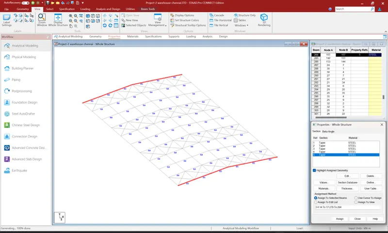
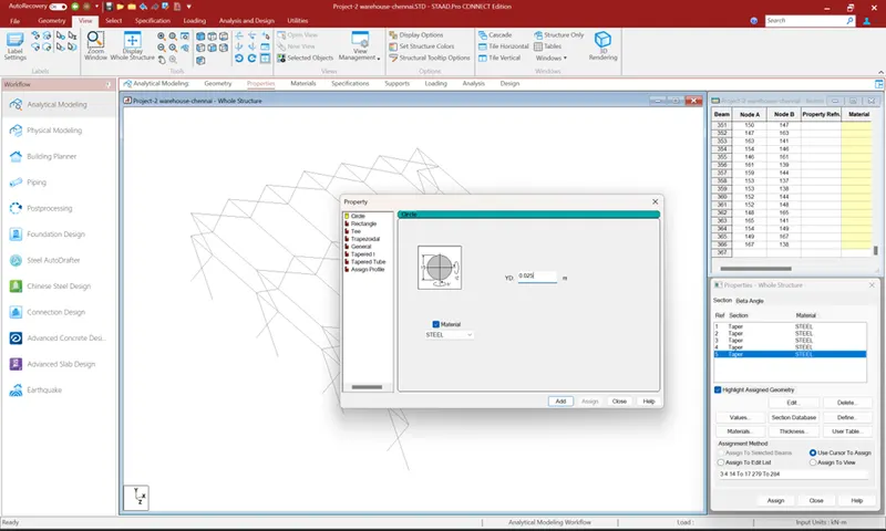
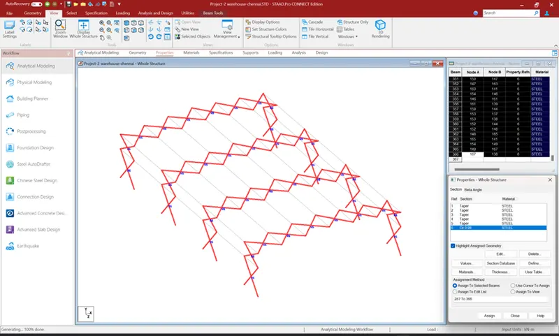
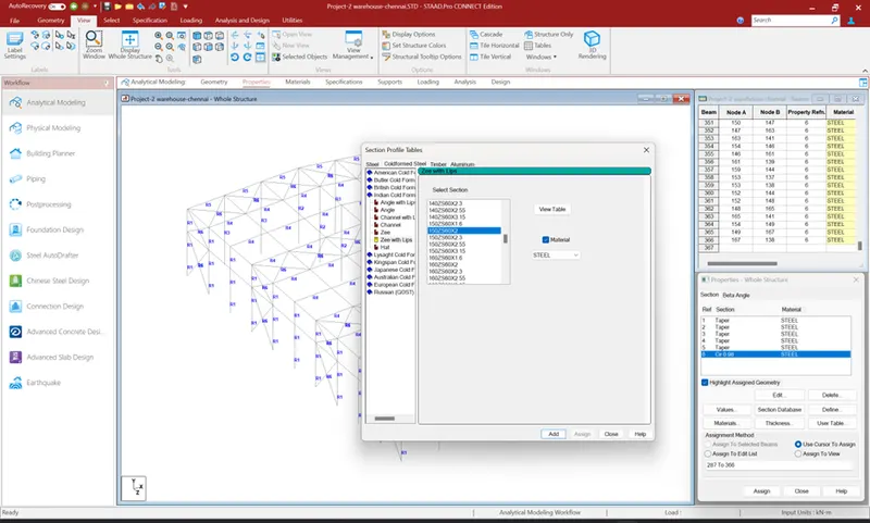
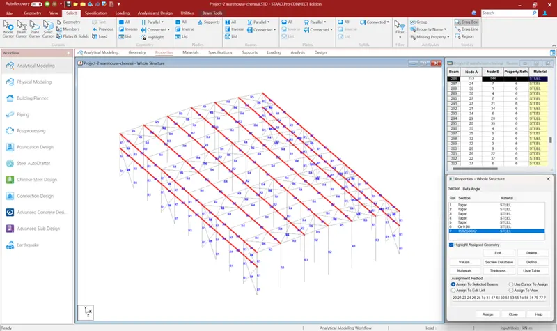
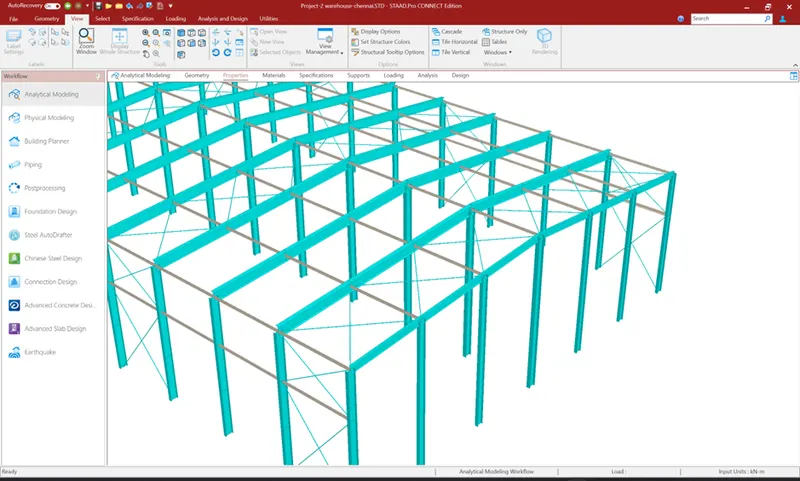
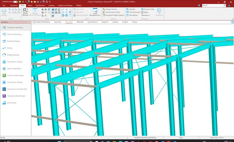
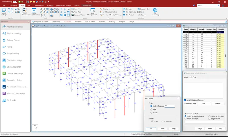
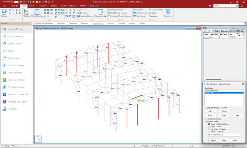
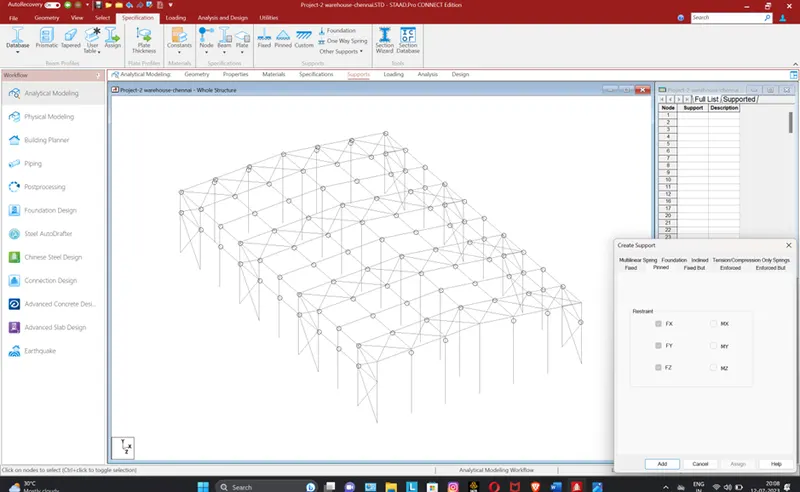
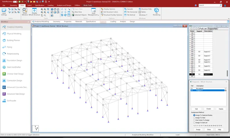
- Create structural model using STAAD Pro Connect Edition
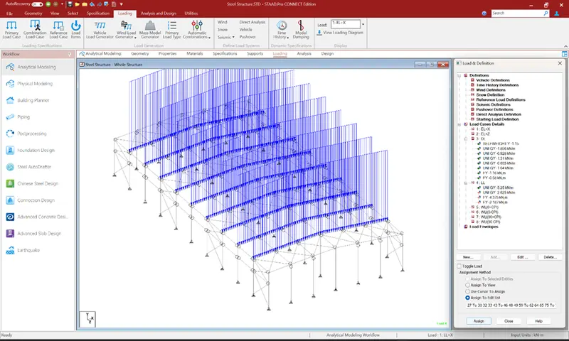
- Prepare DL, LL, WL and EQL load calculations as per IS 875 standards
- Design using MS – Excel
- Steel column
- Rafter
- Base plate
- Pedestal
- Z- purlin
- Design Foundations using STAAD Foundation.
- Attach necessary sketches and drawings wherever required.
- All stipulations, assumptions and design parameter must adhere to Indian Standards.
Dead Load (DL):
Roof Dead Load:
Assuming a reinforced concrete roof with a thickness of 0.15m and a density of 25 kN/m³:
DL roof = thickness x density = 0.15m x 25 kN/m³ = 3.75 kN/m²
Floor Dead Load:
Assuming a reinforced concrete floor with a thickness of 0.15m and a density of 25 kN/m³:
DL floor = thickness x density = 0.15m x 25 kN/m³ = 3.75 kN/m²
Wall Dead Load:
Assuming a masonry wall with a thickness of 0.3m and a density of 20 kN/m³:
DL wall = thickness x density = 0.3m x 20 kN/m³ = 6 kN/m²
Total Dead Load:
DL total = DL roof + DL floor + DL wall = 3.75 kN/m² + 3.75 kN/m² + 6 kN/m² = 13.5 kN/m²
Live Load (LL):
Assuming an occupancy category of storage, with a live load of 5.0 kN/m²:
LL_total = 5.0 kN/m²
Earthquake Load (EQL):
Importance Factor (I):
Based on the occupancy category, the importance factor is 1.0 for storage.
Response Reduction Factor (R):
For Chennai, in seismic zone 3, the response reduction factor (R) is typically 5.0 as per IS 1893.
Zone Factor (Z):
For Chennai, in seismic zone 3, the zone factor (Z) is typically 0.16 as per IS 1893.
Design Horizontal Acceleration (Ah):
Ah = Z x g, where g is the acceleration due to gravity (approximately 9.81 m/s²).
Ah = 0.16 x 9.81 m/s² = 1.57 m/s²
Earthquake Load:
EQL = R x (DL_total + LL_total) x Ah
EQL = 5.0 x (13.5 kN/m² + 5.0 kN/m²) x 1.57 m/s² = 104.08 kN/m²
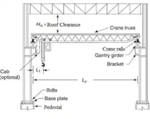
2. Design a simply supported gantry girder to carry electric overhead travelling crane
Given:
Span of gantry girder = 7 m
Span of crane girder = 9 m
Crane capacity = 250 kN
Self-weight of trolley, hook, electric motor etc. = 40 kN
Self-weight of crane girder excluding trolley = 100 kN
Minimum hook approach = 1.0 m
Distance between wheels = 3 m
Self-weight of rails = 0.2 kN/m
Given
Moment Load of maximum moment
Crane capacity + Self weight of trolley
250 + 40 = 290 kN
Self weight of the crane girder is 100 kN
For maximum reaction on gantry girder, The moving load should be as close to gantry as possible.
MB=0
RA x 9 – 290 x 8 -100 x 4.5 = 0
9RA = 290 x 8 + 100 x 4.5
RA = 290 x 8 + 100 x 4.5 / 16
= 173.12 kN
This load is transferred to gravity gantry girder through two wheel
The wheel base being 3 m
Load gantry Girder from each wheel = 173.12/2 = 86.56
Factored wheel load = 186.56 x 1.5 = 129.87 kN
Maximum moment due to maximum loads of calls under a wheel when the center of gravity of wheel load and the wheel are equidistant from the center of gravity
MB=0
-RB x 7 + 129.84 x 2.25 + 129.84 (4.5+0.75)=0
7RB = 129.84 x 2.25 + 129.84 (4.5+0.75)
RB = 129.84 x 2.25 + 129.84 (4.5+0.75)/7
RB = 486.9 kN
Max Moment ME = Force x Perpendicular
ME = 486.9 x 3.75
= 1825.87 kNm
25% of ME = 0.25
Moment due to Impact = 0.25 x 1825.87
= 456.46 kNm
Assume self weight of girder = 2kNm
Therefore DL due to self weight + rails = 2 +0.2
= 2.2 kNm
Factored DL = 2.2 x 1 = 2.2 kNm
Moment due to DL = 2.2 x 72 / 4.5 = 23.95 kNm
Max moment ME + Moment due to Impact + Moment due to DL
1825.87 + 456.46 + 23.95 = 2306.28 kNm
MAX MOMENT DUE TO HORIZONTIAL FORCE
Horizontial force transfers to rail: 10% of weight to rail + load lifted
10/100 (250 + 40) = 29 kN
Assume double frame wheel, This is distributed over 4 wheel = 29 / 4 = 7.25
Factored horizontial force on each wheel = 1 x 7.25 = 7.25
For maximum shear force on the girder the trailing Wheel should be just on the girder
Therefore vertical shear due to wheel loads = 129.84 + 129.84 x 3.5 / 7 = 194.76 kN
Vertical due to impact = 0.2 x 194.76 = 39.35 kN
Vertical shear due to self weight = 2.2 x 7 / 2 = 7.7 kN
Total vertical shear = 194.76 + 39.35 + 7.7
= 241.81 kN