Project 2
AIM
Is to create the core and cavity blocks with proper dimensions for the given model and create ejector system, Sliders, Air Vent, Cooling System, Runner and Gate and Washers and bolts
PROCEDURE
- First analysis the given plastic component by using Draft Analysis option for the correct Tooling direction.
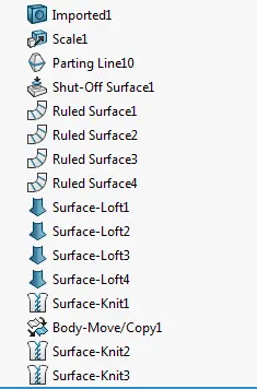
- After giving draft use Scale option to increase the shrinkage of the component and shrinkage value is given as per the data.
- After scaling use Parting Line option to indentify the line in given plastic component to separate Core and Cavity.
- If there is holes in the component use Shut Off Surface option to close the holes.
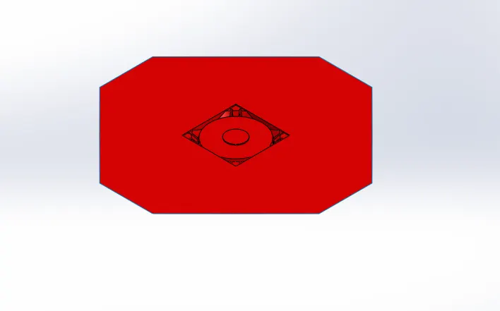
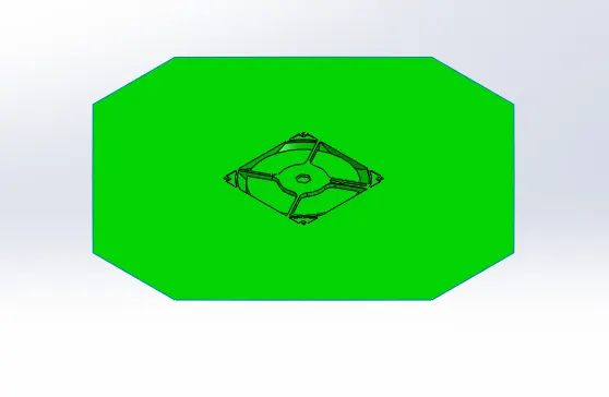
- After separating the core and cavity colour will change Green is Cavity and Red is Core and folder is created in the feature tree.
- After spliting use Ruled Surface option to create parting surface.
- For the curved corners use Lofted Surface option and to join the surfaces use Knit Surface option.
- To make a copy of the parting surface use Move/Copy Bodies option it will be in Direct Editing
- To coimbine core and cavity with the parting surface use Knit Surface option.
- Go to Assembly option and create a assembly.
- After creating a assembly design bring the created core and cavity part in the assembly design.
- Create a new parts by using Insert Components option and name it as Core Steel and Cavity Steel.
- After creating go to core steel and create two rectangle sketch.
- To create a block create two rectangle sketch and use Extruded Boss/Base option for extruding the sketch and use Offset Surface option to offset the core surface.
- To cut the required position of the block use Cut with Surface option for both core and cavity and give colour to the block.
- For the big rectangle use Extruded Boss/Base option and to reduce the block size use Move Face option.
- After completing the process done the same process for Cavity Steel.
- At last in core and cavity there should be some relief for that use Move Face option to create gaps for the relief for the easy movement.
- Create a plane in the undercut area by using Referance Plane option and create a sketch by using Convert Entities option.
- After creating use Split option to split the cavity and slider after spliting it show as split 1 and 2.
- In slider create remaining sketch and extrude using Extruded Boss/Base option.
- In between split and undercut there will a gap for that again use Extruded Boss/Base option.
- Inside the split 2 there will some surfaces to remove use Cut Extruded option.
- For the slider create a sketch as per the given data as use cut and extrude by using Cut Extruded and Extruded Boss/Base option.
- Slider should be fit in the Core and Cavity mold block for that take a copy of the slider and use Combine option and select subtract option.
- To close the holes and gaps create a rectangle sketch and extrude using Extruded Boss/Base option and for gaps use Move Face option and select offect option.
- In assembly create a New Part and name as Slider and after creating import the slider part in the slider folder by going to insert - feature - imported.
- In Core block slider movement should be available for that create a sketch and cut the area by using Cut Extruded option.
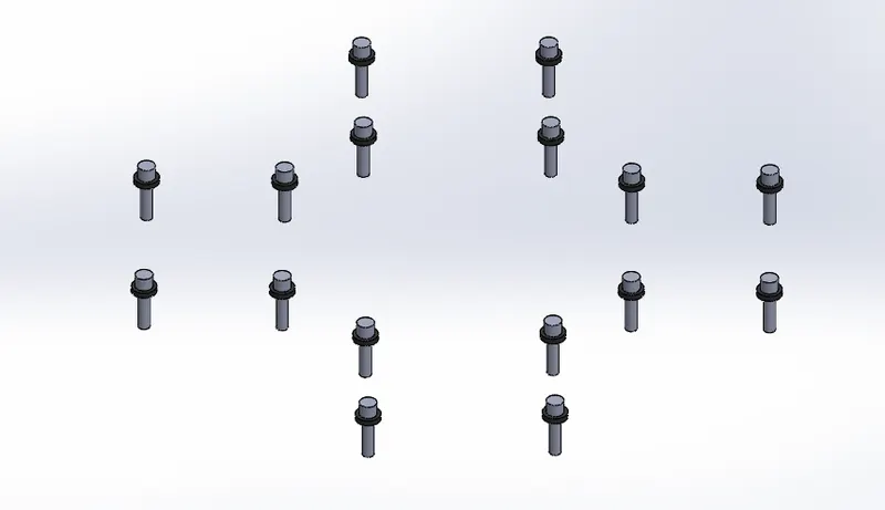
- For washers and bolt create a rectangle sketch as per the data given and extrude it and some position is removed in the slider for that create a sketch and use Cut Exturded option.
- Give fillets to the edges in the core, cavity and the slider by using Fillet option.
- In cavity create a circle sketch and cut using Cut Extruded option for the Bolt.
- For Locking Mechanism create a sketch in the core as per the given data as create another sketch in the slider as cut using Cut Extruded option.
IMAGES OF CORE AND CAVITY SURFACE
FEATURE TREE
IMAGES OF CORE AND CAVITY STEEL
FEATURE TREE
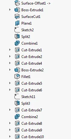
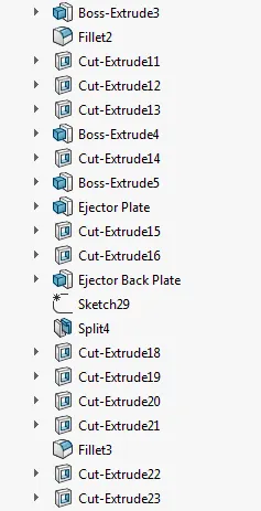
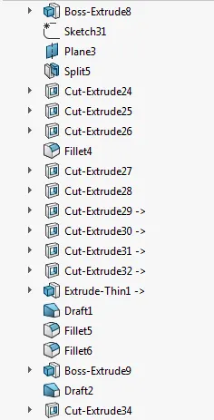
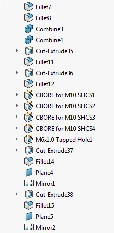
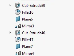
FEATURE TREE
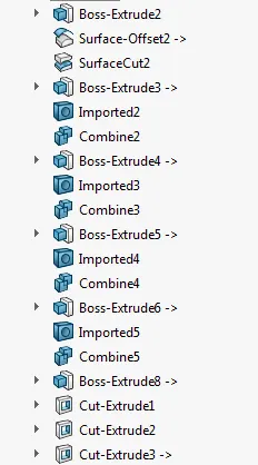
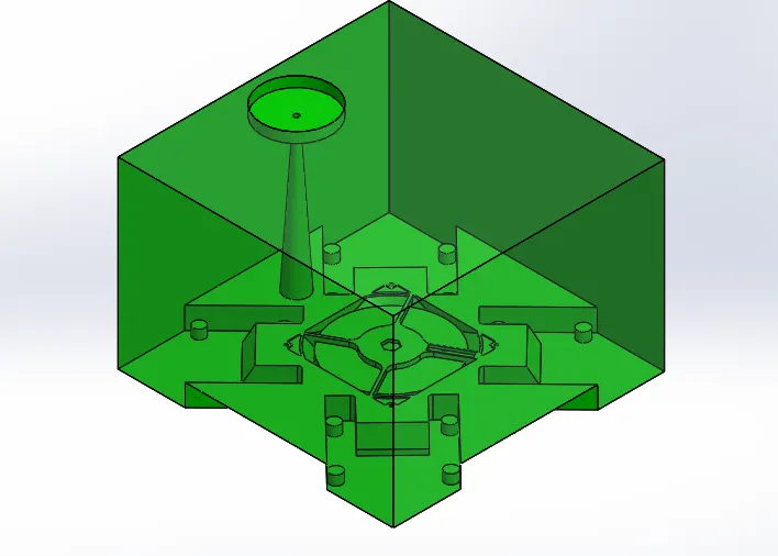
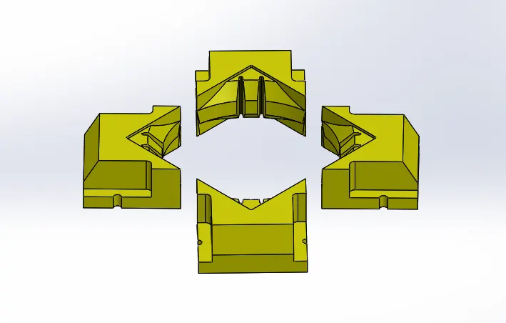
iMAGES OF SLIDERS
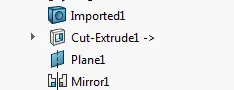
FEATURE TREE
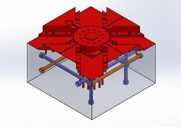
IMAGES OF WASHERS AND BOLTS
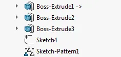
FEATURE TREE
PROCEDURE FOR EJECTOR SYSTEM
- For creating Ejector Pin first create a Plane using Reference Geomentry option and use circle profile to create circles and cut it using Extruded Cut option.
- Using the same circle sketch and use Extruded Boss/Base option to extrude the circle for creating Ejector Pins.
- For Relief create a circle using circle profile option and cut it using Cut Extruded option.
- For creating a circle Head create a circle and line sketch using circle profile and extrude using Extruded Boss/Base option.
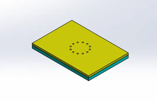
- For creating Ejector Plate create a rectangle sketch using rectangle profile option and extrude using Extruded Boss/Base option.
- For creating Ejector Back Plate create a rectangle sketch using rectangle profile option and extrude using Extruded Boss/Base option.
IMAGE OF EJECTOR PIN
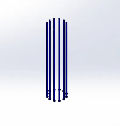
IMAGE OF EJECTOR PLATE AND BACK PLATE
PROCEDURE FOR RUNNER AND GATE
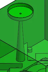
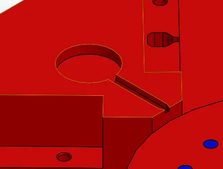
- First create a circle using circle profile option and cut it using Cut Extruded option.
- Again create a circle using circle profile option and cut it using Cut Extruded option and give some draft.
- In core near the spure create a circle using circle profile option and cut it using Cut Extruded option.
- For creating a Runner create a line sketch and extrude using Extruded Boss/Base option and in that use thickness option and give draft by using Draft option and give some fillets using Fillet option.
- For creating a Gate create a line sketch and extrude using Extruded Boss/Base option and give draft by using Draft option give some fillets using Fillet option.
- Finally join the Runner and Gate using Combine option in that use add option and Sub it using Combine option.
IMAGE OF SPURE, RUNNER AND GATE
PROCEDURE FOR AIR VENT
- Create a rectangle sketch and extrude using Extruded Boss/Base option.
- And give some fillets to the edges using Fillet option.
- Do the same process of another offset sketch and join it using Combine option
- After that create a line sketch at the end of the body and do the same process as pevious done.
- And add the two bodies using Combine option.
- For other side use Mirror option and Sub it using Combine option.
IMAGE OF AIR VENT
PROCEDURE FOR COOLING CHANNEL
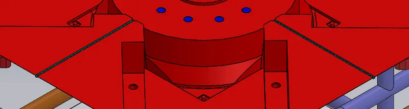
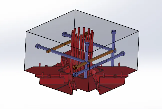
- For creating Cooling Channels use Hole Wizard option as per the given data in the front plane
- Do the same process for the right plane and top plane.
IMAGES OF COOLING CHANNEL
FINAL MOLD DESIGN
FEATURE TREE