Project 2
- Topograhical Survey is required to fix the horizontal and vertical alignment.
Topographic surveys consist of determining the horizontal and vertical locations of objects on the surface of the earth.
Topographic surveys show the nature of the ground or profile of ground which is the most essential part for proper road alignment.
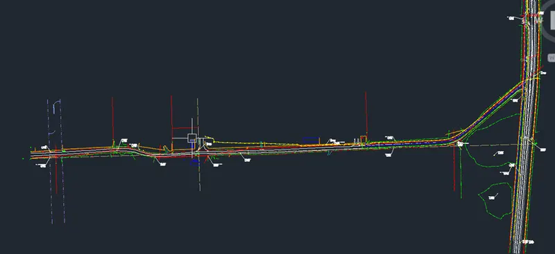
Create GTMRD01 Survey surface using topograhical data.
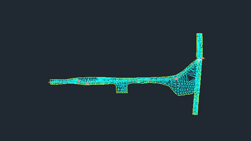
- Create ALGNRD-01 file for Alignment and Profiles
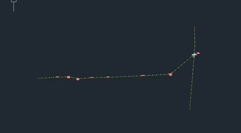
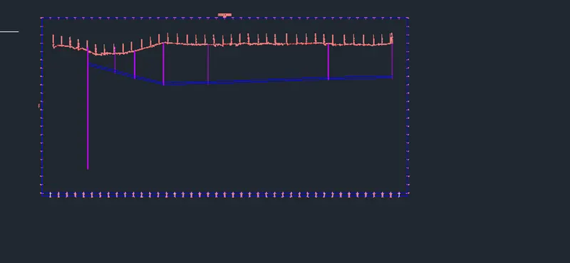
- Create Profiles of the Alignment.
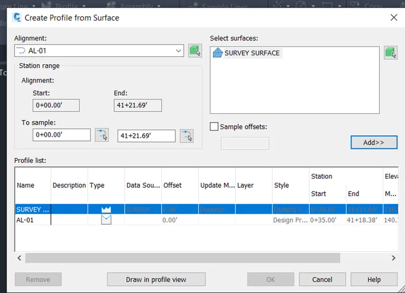
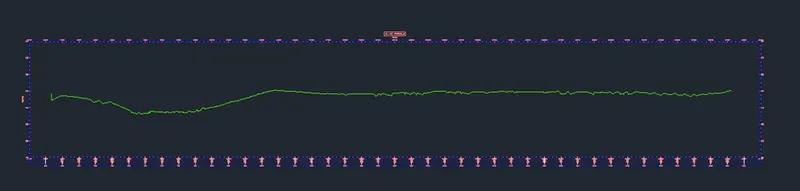
- Create Design Profile
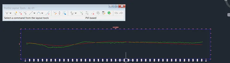
-
Alignment in Design
Alignment is a design principle that refers to lining up text or graphics on a page. A design with poor alignment will look cluttered and unfinished. But aligning elements on the page will organize your design and make it easier to read.
Horizontal Alignment Definition
The horizontal alignment is the route of the road, defined geometrically as a series of horizontal tangents (straight roadway sections), circular curves, and spiral transitions. It shows the proposed roadway location in relation to the existing terrain and adjacent land conditions.
Road Alignment
Road alignment is the positioning of the centreline of the highway or road. It is also called as highway alignment. Simply, it is the direction through which the road will pass. Road alignment provides a proper guidance to pass the road through the alignment which is most economical, easy to construct and free from conflicts.
Vertical Alignment of Road
The vertical alignment of a road consists of gradients (straight lines in a vertical plane) and vertical curves. The vertical alignment is usually drawn as a profile, which is a graph with elevation as a vertical axis and the horizontal distance along the centre line of the road as the horizontal axis.
5 Create Assembly and Sub-Assembly in MODLRD-01 File.
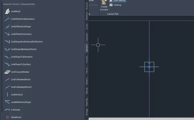
- Using Tool Palette try to create Assembly and after changing its Parameters, Mirror it.
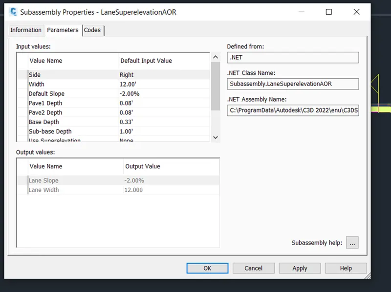
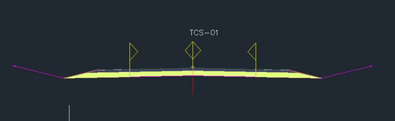
Create Corridor using Assemblies.
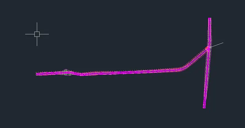
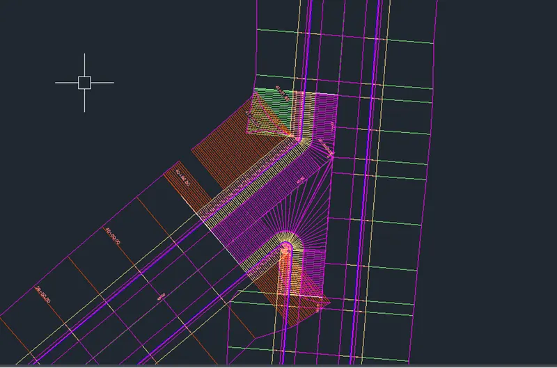
Create Junction using Assemblies.
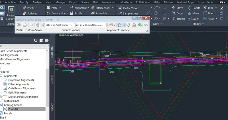
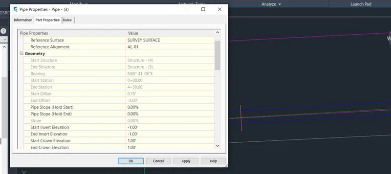
- Create PDLPRD-01 file for Pipe Network
- Create a pond in given surface data
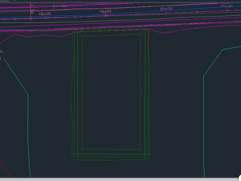
- Convert the PL line to feature line and provide gradient to the pond
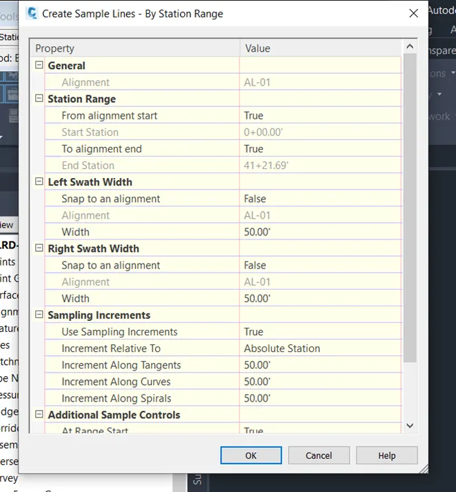
Create Sample Lines Group
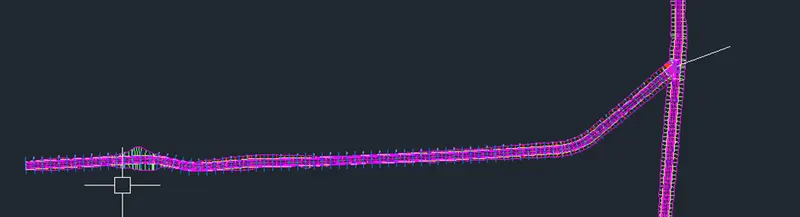
Go to Sections
Compute Materials
Add Existing Surface and Corridor Bottom Surface
Create Sections Multiple Views
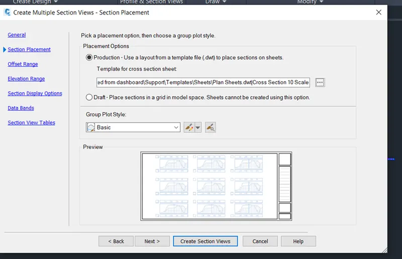
Cross-sections
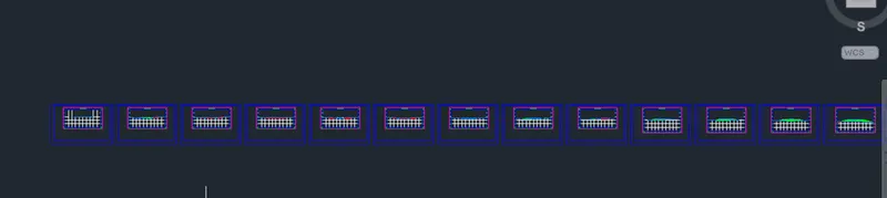
- For Sheeting
Go to Output
Create Section Sheets and Add in same or Different DST file.
Scale need to be set accordingly.
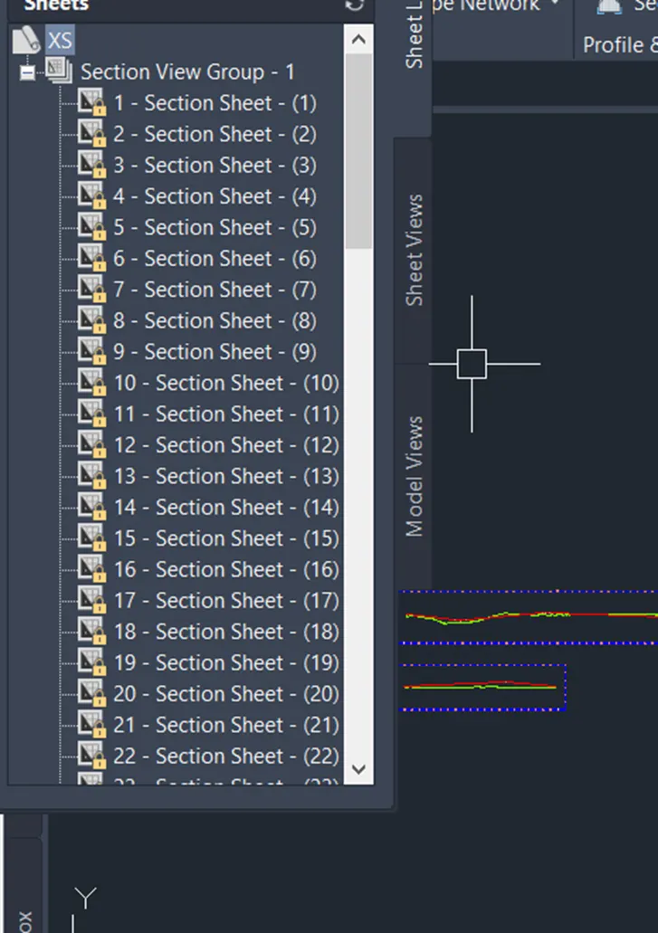
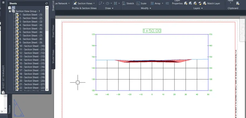
- Preparing QTSRD-01 Sheet
Import Agency Sheet
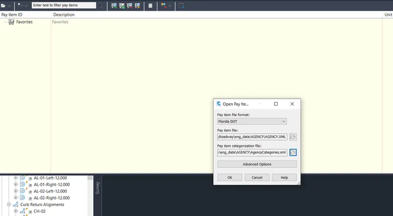
Select the Item and add to favorites and takeoff to get the quantity of the selected layer.
Add all the data in excel sheet and calculate the quantities.