Project 2
AUTOMOTIVE WIRING HARNESS BACKDOOR
Statement of assignment:
Route the Wiring harness on Given car body and Prepare flatten view drawing in CATIA V5. Application of all Packaging rules, Industry best practices studied in this course shall be demonstrated in design. Apply Protection coverings as required.
Available connector 3D data can be used, or you can download the connectors from www.te.com
Prepare & Submit all necessary reports like clearance, Clipping/Clamping selection, Harness fixing requirements, Harness continuity, Assumptions if any along with CATIA 3D data.
Introduction-
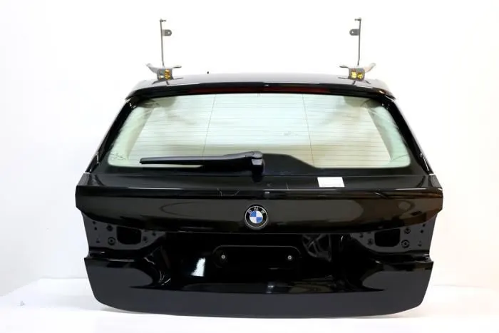
The trunk or boot of a car is the vehicle's main storage or cargo compartment it also have a hatch at the rear of the vehicle. It is also called a tailgate.These doors can be operated manually or electric powered. here we design the trunk or back door wire harness using the Catia.The Backdoor is an assembly of many parts such as inner panel, outer panel upper, outer panel lower and Reinforcement.Inner panel is attached to the outer panel using mastic sealant.
Types of doors based on working position
- Top Mounted Door
- Side mounted Door
- Bottom Door
Aim- To route the wiring harness on the given backdoor assembly and prepare the flatten view drawing in CATIA V5.
OBJECTIVE
- Define all the mechanical connectors electrically and save it in the Catalogue.
- Place required Connecters on the Back door CAD data.
- Place Fir Tree clips at the required position by following the packaging rules.
- Create the Wiring Harness Routing with all the electrically defined connectors and mounting equipments.
- Create branching points at required locations to create sub branches and connect to various connectors in the geometrical bundle.
- Apply Protection coverings as required.
- Create Wiring harness flattening for the final geometrical bundle.
- Using the drafting workbench, create a drawing sheet with the flattened wiring harness.
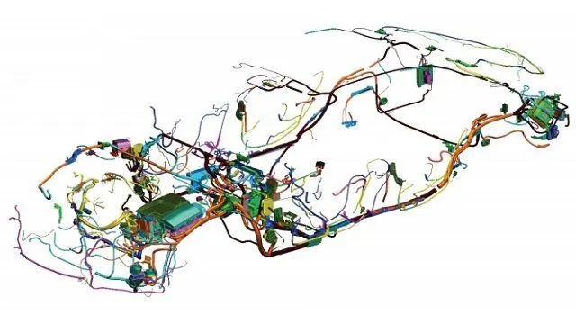
The objective of this project is to route the wiring harness and prepare flatten view drawing for the Backdoor of the car. All types of packaging rules have to be considered while routing the harness and industry based practices shall be demonstrated in harness design. All necessary details like clearance, clipping/clamping selection, harness fixing requirements, harness continuity should be provided in order to design the wiring harness.
Rules to be followed-
- Wiring harness should be routed in such way that it is easy to assemble and access.
- Easy manufacturing, installation, removal and maintenance have to be considered while designing the wire harness.
- Wiring Harness should be kept away from sharp environment like edges, corners etc.
- Avoid harness routing and clipping in the blind zones or hard to reach areas during harness assembly or service.
- Provide additional slack if needed according to the surrounding and harness bending requirement. If harness is passing through the closures/doors or tail gates then envelope dimensions during opening and closing of doors shall be considered to provide the slack. Check the harness slack requirements with open and close conditions to avoid excess slack.
- Routing through small structural holes and openings shall be avoided. To minimize chaffing and handling of the wiring harness during installation.
- It should be make sure that there is no case of fouling while designing the wiring harness in the CAD environment. Additional mounting equipments like clips/clamps may be used to avoid fouling.
- Use of rubber grommet is recommanded if harness is passing through sheet metal panels. Example- firewall, passing to door, tail gate etc.
- The branch length should be greater than 50mm.
- The minimum distance between the clip and branch point should be at least 25mm.
- The minimum distance between the two branch points should be at least 50mm.
- Clips/clamps used for the wiring harness should be easily available in the market to avoid extra cost for custom mounting solutions.
TECHNICAL SPECIFICATIONS AND ASSUMPTIONS:
Wiring harness routing shall be ease in manufacturing, accessibility, maintenance and removal.
Avoid routing through small structural holes, bolts, bolted joints, screwed joints to avoid harness puncture
Provide additional slack to the harness according to the surrounding and harness bending requirements.
Provide additional slack to the harness branch which connects to the loads and covered with enclosures.
Avoid routing near sharp edges or over the sharp edges, in case of non avoidable situations additional protection should be provided.
Ensure harness is routed atleast 100mm away from ABC pedals.
Enough clips and clamps shall be provided to ensure the positive clearance with surroundings and safety of wiring harness.
Keep the harness away from engine heat generation components, heating lines and EGR components.
Avoid direct support of harness on fuel lines routed in engine, in that case a separator clamp to be provided to satisfy clearance requirements.
Harness branch length should minimum 50mm.
Minimum distance between clip and nearest branching point should be 25mm.
Limit the number of branches from single branching point to 4.
Harness Protection should be provided according to the surrounding temperature.
Clips/Clamps that are used should be selected such that they are easily available in the market.
The given car body hatch focuses on different areas of study under which comprises of routing harness bundles for two tail lamps and two number plate lights which connects the car main electrical system.
For all these four lights a Deustch 2 pole connectors are used (DT06-2s) and a an Interconnection connector which connects from car body hatch to the main car body wiring harness and is used at a preferred location from where the routing for these lights starts. For interconnection 12 pole connector is used.
As for the mounting parts clips/clamps which are used where ever necessary, hellerman mounting clip and fixing clips are used.
Step 1: Creating Context Assembly
- We have created context assembly for the tail gate of the car as main assembly as shown in above figure.
- This context assembly contains the 3D cad data for the tail gate of the car and car tail gate harness geometrical bundle.
Step 2: Difining 2-pole and 8-pole connectors electrically
Here, according to the requirement, we are using
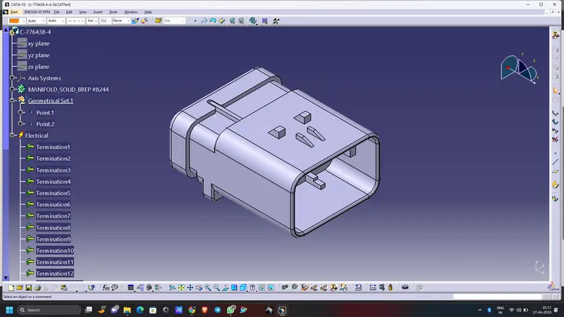
- ‘C-776438’ Which is a 12 Pole connector is used as an inline Connector
- 'C-DT06-4S' which is a 4-pole connector for Taillight
- 'C-DT06-2S' which is a 4-pole connector for Number Plate Light
This CAD data was obtained from te.com. To electrically define a connector, we must first define the geometrical parameters such as the bundle connection point and connector connection point in the Electrical Part Design workbench for the downloaded connector.
- Here, we will use 2-Pole and 8-Pole connectors for this assembly and for that we have downloaded these connectors from TE.Com
- We should have to define it electrically that is to define geometrical parameters, bundle connection point and connector connection point.
- Here, we have defined 2-Pole connector electrically for two number plate lights of the car as shown in above figure.
- In above figure, we have defined 8-Pole connector electrically for two tail lights of the car.
Step 3: Adding connectors to the 2 tail lights and 2 number plate lights
- We have added both 2-pole connectors and 8-pole connectors inside the tail gate harness geometrical bundle assembly.
- We have used commands like manipulation, compass, snap and smart move to place all the 4 connectors to their desired location.
- We have placed all the connectors at their desired position as shown in below figures.
Step 4: Defining and locating interconnection connector
- A 12-pole "C-776438-4" is used as an interconnection connector and "C-1924487-2" as mounting cavity.
- The 3D CAD data files for interconnection connector and cavity are downloaded from TE.com
- We have defined interconnection connector and mounting cavity electrically in Electrical Part Design workbench as shown in above figure.
- As shown in above figure, we have electrically connected both an interconnection connector and mounting cavity in Electrical Assembly Design workbench.
- After defining an interconnection connector electrically, we have mounted it near top slot on the tail gate of the car as shown in above figure.
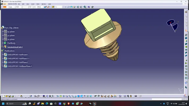
Step 5: Defining mounting clips as support
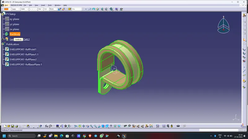
- We will be using Hellermann Tyton mounting clip for the mounting purpose.
- We have to define geometrical parameters, bundle entry points and exit points from both left and right side of the clip.
- We have defined these clips electrically as a support in Electrical Part Design workbench as shown in below figures.
Step 6: Mounting Clips at desired location
Here, we have used 6 bundle clips which have mounted at desired location as shown in below images.
IMAGGES OF THE CONNECTORS AND CLIPS DEFINED:
Connectors definition:
The following parameters are required to define any connector:
Geometry Parameters: Points & Co - ordinate system ( Axis ) .
Connector connection points: This point is used for the connection of one connector to another connector.
Harness bundle entry point: This point defines where the harness bundle segment point will end when routed to the electrical connector.
Cavity connection point (Optional) : This point is used to define the connection of a connector to a connector clip . This only applies to connectors that have the mounting feature for a connector clip.
Step 7: Bundle routing
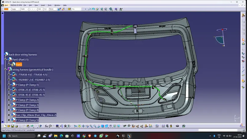
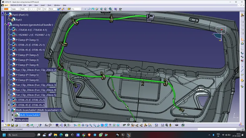
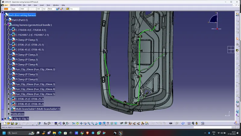
Before, bundle routing we have to make a curve by creating points in hollow part of the given tailgate. So we have made a curve through 11 points from the interconnection connector as shown in below image.
- Now, the car tail gate assembly is ready for the bundle routing as shown in below image.
- Also, we have activated harness assembly as geometrical bundle.
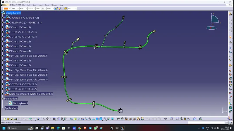
- Let, we have started bundle routing from interconnection connector and assumed diameter of main trunk is 12mm.
- The diameter of bundle leading to 2 tail lights and 2 number plate lights is 8mm and 5mm respectively.
- The bend ratio is assumed to be 1.4 and appropriate slack between 1-10% is given wherever needed.
IMAGES OF THE BUNDDLE ROUTING:
FLATENING AND DRAFITING:
Flatterning:
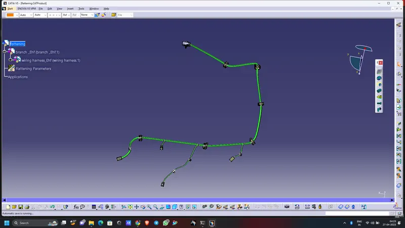
- Create a product file and navigate to the Electrical Harness Flattening for wire harness flattening option and save it in the same location where the wire harness or routing assembly is stored.
- Define the 'Harness flattening parameters' in order to flatten the required wire harness assembly.
- While defining the harness flattening parameters in the drawing menu single line is selected for bundle segment and double line is selected for protective coverings in order to differentiate between the wire bundle and cot tubes in drafting.
- Select the 'Extract' option from the Electrical Harness flattening workbench and select the Geometric bundle product in the wire harness assembly product file.
- Then wire harness assembly is imported to the Wire flattening product file with 'EHF' extension added to the geometric bundle assembly name.
- Select the 'Flatten' option to flatten the wire harness assembly.
- Then select the active plane, then select any one branch and then select the 'select all branches'.
- Save the product file using 'Save management' option so that all the related product files and part files are stored in single directory.
Conclusion -
Routing of the wiring harness for the car tail gate assembly has done and prepared flatten-view drawing in Catia V5. Applied all the packaging rules while routing the wiring harness, implemented industry best practices in the harness design. Also, provided details like clearance, clipping selection, harness fixing requirements, harness continuity in order to design the harness.
Routing of the wiring harness for the car Backdoor assembly has been succesfully done and prepared flatten-view drawing in Catia V5 as per the design requirements.