Project 2
BACK DOOR WIRING HARNESS ROUTING
AIM:
- Route the Wiring harness on Given car body and Prepare flatten view drawing in CATIA V5.
- Application of all Packaging rules, Industry best practices studied in this course shall be demonstrated in design.
- Apply Protection coverings as required.
PACKAGING RULES AND ASSUMPTIONS:
- Provide Enough Clearance to the wiring harness with respect to the surrounding
- Avoid harness routing and clipping in blind zone
- Provide additional slack to the harness according to the surrounding. 5-10% of slack
- Branch length should maintain with 50mm
- Minimum distance between clip and nearest branching point should be 25mm
- Minimum distance two breakouts should 50mm
WORKING PROCEDURES:
STEP 1:
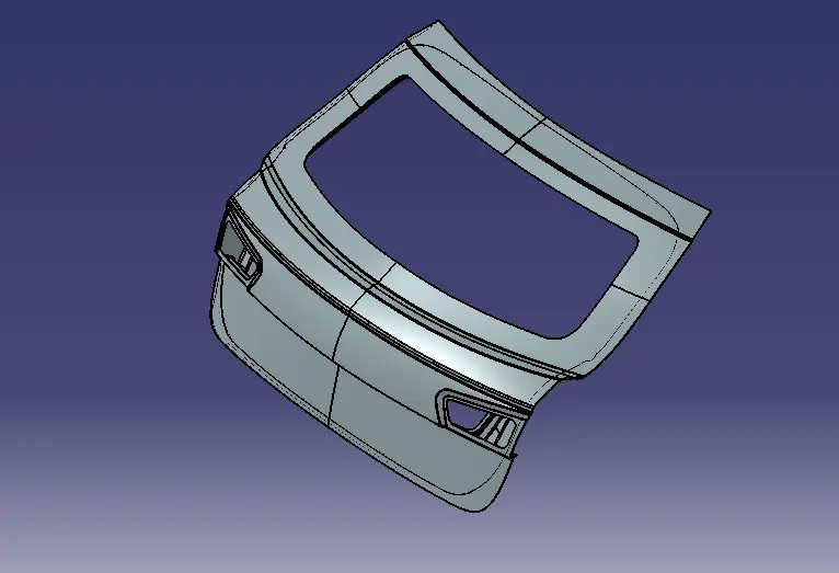
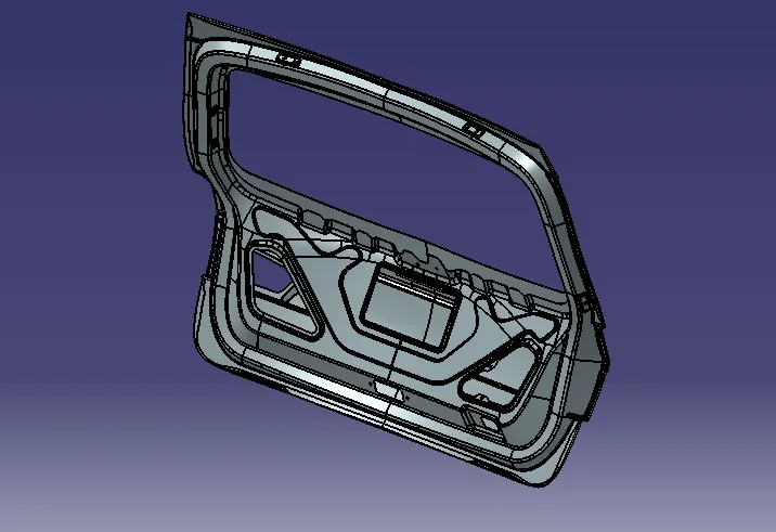
Download 3d Model from given Website
STEP 2:
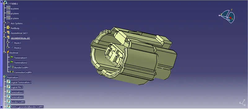
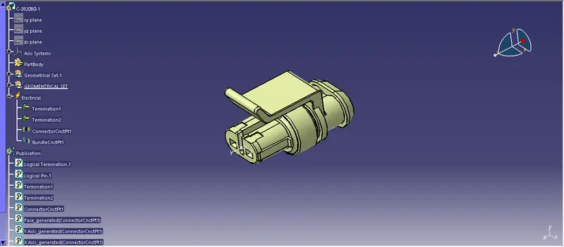
- Download all Connectors from Website and Defined Electrically Abby Geometrical Sets
- Points and Axis Sytems are used to defining the Connectors
- Define 3 Pole connector by Electrical Part Design workbench
- Define a 2 Pole Connector
- Define a 4 Pole Connector
- Define a Inter connection Point in a 12 pole connector
- Firr tree clip these clip defined by support part definition. It has 2 bundle entry Points and one Base Point
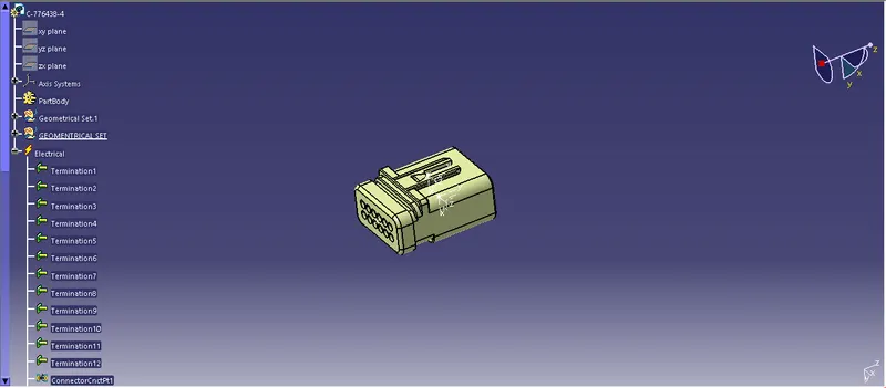
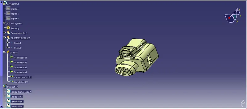
STEP 3:
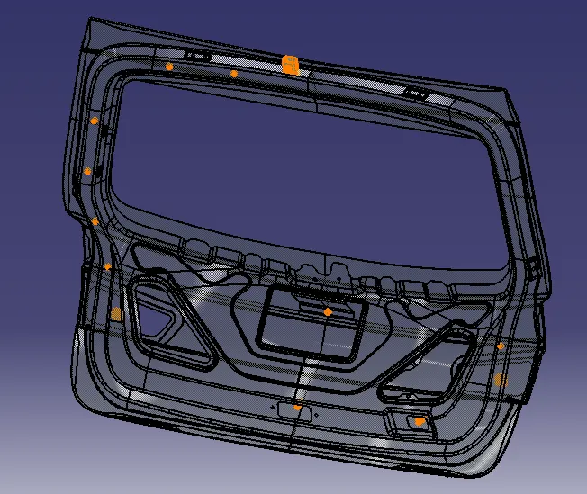
BACK DOOR WIRING HARNESS CONNECTORS AND FIRR TREE CLIPS PLACEMENTS
STEP 4:
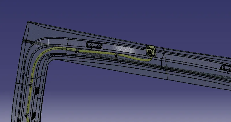
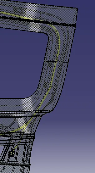
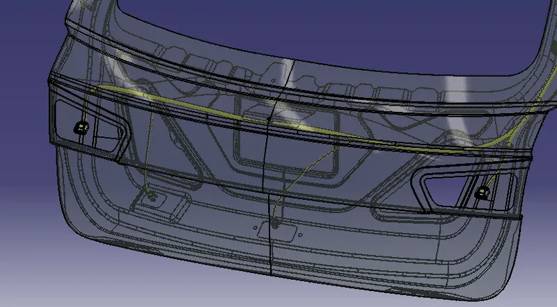
- Routing start with Inter Connection Connection Point to the Fir Tree Clip.
- Click on Geometrical budle command by convert to Electrical assembly.
- After Converted Start Routing with Connectors.
- Click Multibranchable to give diameter of bundle 10mm.
- Bundle bend radius must have 1.4 or 1.5 times greater than bundle Dia.
- Slack is given additional for avoiding clashes or anyother errors.
- Same Routing Procedure are followed by All bundle Connection.
STEP 5:
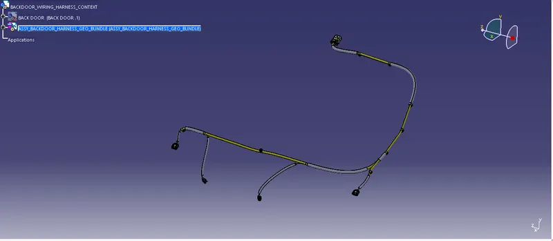
Add COT Tubes for protective covering
STEP 6:
CHECKING BUNDLE CONTINUITY:
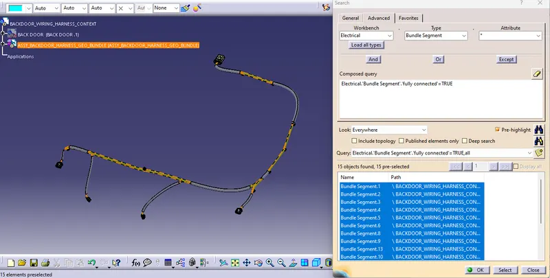
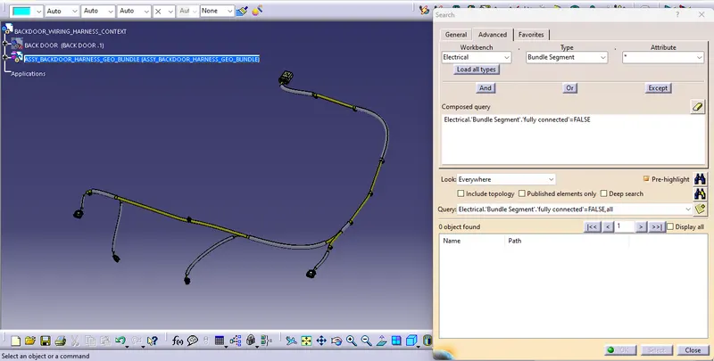
- First, we have to make sure that multi branchable is selected and then we have to go in WORKBENCH>TYPE-BUNDLE
- EDIT>SEARCH>ADVANCED>ELECTRICAL
- SEGMENT>ATTRIBUTE-FULLY CONNECTED
- Selecting the "TRUE" option will show all the connected bundle segments while the selecting "FALSE" will show all the non-connected bundle segments.
- For now, we will select "TRUE" and search for results. All the bundle segments are highlighted and found showing that all the bundle segments are electrically connected.
STEP 7:
- Geometrical Assy Extraction to Flattening Assembly
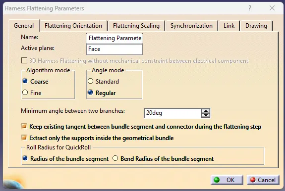
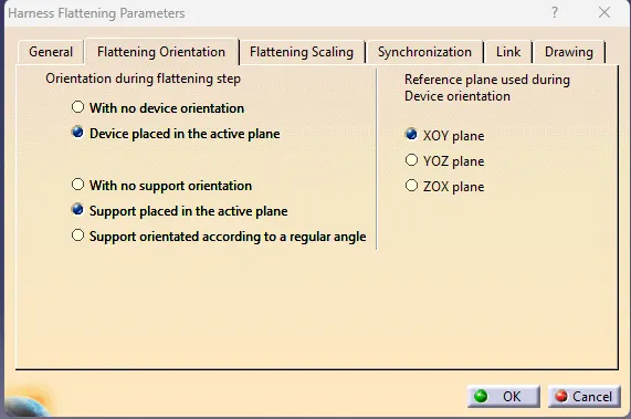
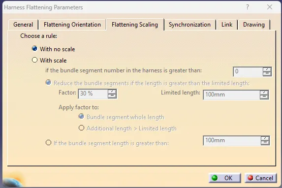
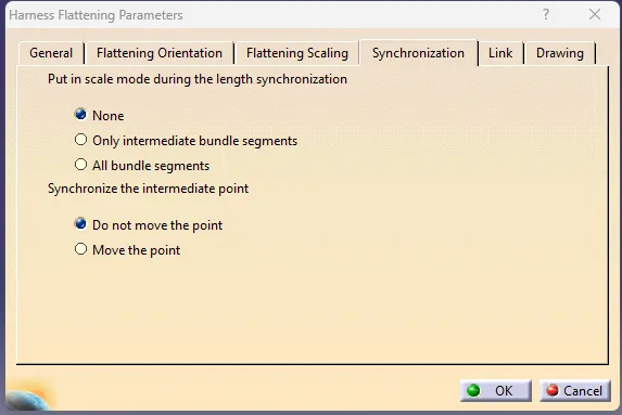
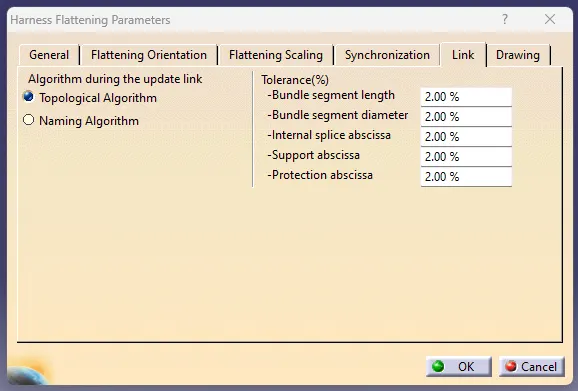
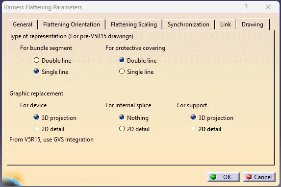
- Before Extraction Switch to the Flattening assembly & set flattening parameters
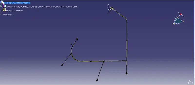
- After Extraction using flatten command to flatten the bundle segments.
FLATTENING PARAMETERS
STEP 8:
ELECTRICAL HARNESS FLATTENING
STEP 9:
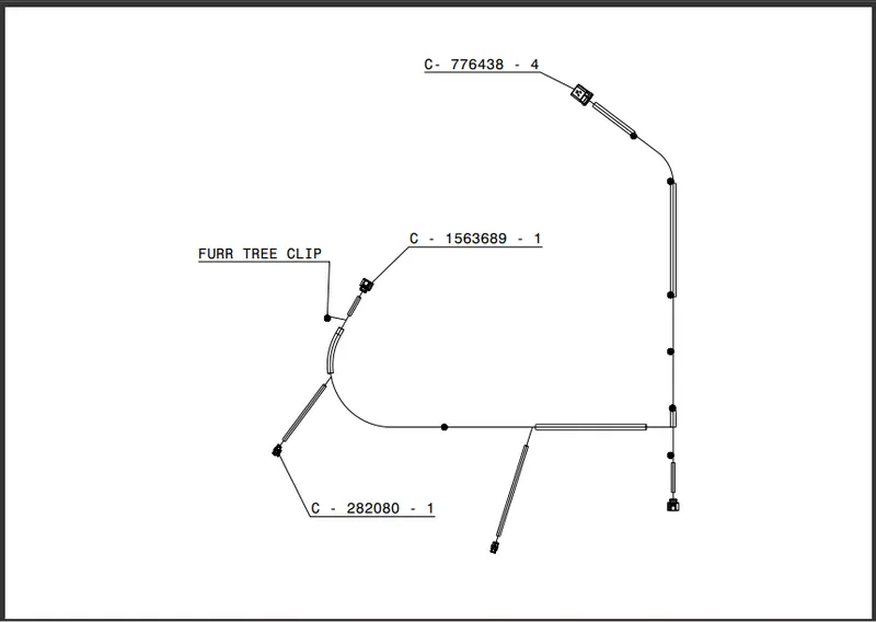
ELECTRICAL HARNESS FLATTENING DRAWING
CONCLUSION:
- Back Door Wiring Harness Assembly Created by using CATIA V6
- After Completed this model. It has been verified or tested by Electrical Engineers. If this model Ok continue to Manufacturing Department.