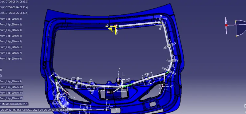
Project 2
Aim: Route the Wiring Harness on given Car body and prepare flatten view drawing in Catia V5
Objective: The objective of this project is to route the wiring harness and prepare flatten view drawing for the tailgate of the car. All types of packaging rules have to be considered while routing the harness and industry based practices shall be demonstrated in harness design. All necessary details like clearance, clipping/clamping selection, harness fixing requirements, harness continuity should be provided in order to design the wiring harness.
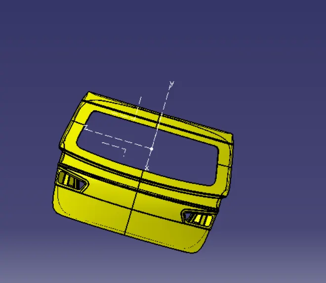
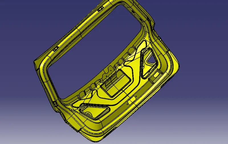
Assumptions:
- Wiring harness should be routed in such way that it is easy to assemble and access.
- Easy manufacturing, installation, removal and maintenance have to be considered while designing the wire harness.
- Wiring Harness should be kept away from sharp environment like edges, corners etc.
- Avoid harness routing and clipping in the blind zones or hard to reach areas during harness assembly or service.
- Provide additional slack if needed according to the surrounding and harness bending requirement. If harness is passing through the closures/doors or tail gates then envelope dimensions during opening and closing of doors shall be considered to provide the slack. Check the harness slack requirements with open and close conditions to avoid excess slack.
- Routing through small structural holes and openings shall be avoided. To minimize chaffing and handling of the wiring harness during installation.
- It should be make sure that there is no case of fouling while designing the wiring harness in the CAD environment. Additional mounting equipments like clips/clamps may be used to avoid fouling.
- Use of rubber grommet is recommanded if harness is passing through sheet metal panels. Example- firewall, passing to door, tail gate etc.
- The branch length should be greater than 50mm.
- The minimum distance between the clip and branch point should be at least 25mm.
- The minimum distance between the two branch points should be at least 50mm.
- Clips/clamps used for the wiring harness should be easily available in the market to avoid extra cost for custom mounting solutions.
- Now, we have to route wiring harness for two tail lights and two number plate lights, and connect them to main electrical system of car.
- For two tail lights and two number plate lights, we are using 8-pole connector and 2-pole connector respectively.
- A car body also have an interconnection connector which will connect the wiring harness of tail gate of the car body to the main harness of the vehicle.
- We will use 12-pole electrical connector with a mounting clip as an interconnection connector.
- The bend ratio for all the bundle segment is considered to be 1.4
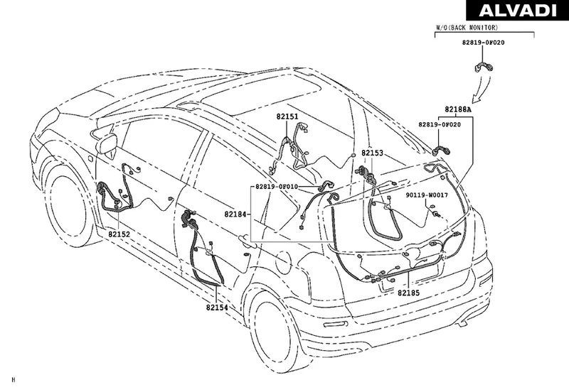
Below are the few references from the real world which were considered while designing the wiring harness for this project
The wiring harness packaging rules and the industry best practices that have to be followed to complete this project are as follows:-
- Easy manufacturing, installation, removal, and maintenance must be considered while designing the wiring harness.
- Routing through small structural holes or openings shall be avoided to minimize chaffing and handling during installation.
- Avoid harness routing and clipping in the blind zone or hard-to-reach areas during harness assembly or service.
- Provide additional slack if needed according to the surrounding and harness bending requirement. For this project, a slack value between 1-5% is used.
- It should be made sure that there is no case of fouling while designing the wiring harness in the CAD environment. Additional clips/ clamps may be used to avoid fouling.
- Avoid harness routing near sharp edges or else protect the harness.
- Enough mounting equipment such as clips and clamps should be provided.
- The branch length should be greater than 50mm.
- The minimum distance between the clip to the branch point should be at least 25mm.
- The minimum distance between the two branch points should be at least 50mm.
- The wiring harness should be easy to assemble and easy to excess.
- Clips/ clamps used for the wiring harness should be readily available in the market to avoid extra costs for custom mounting solutions.
Step 1: Creating Assembly
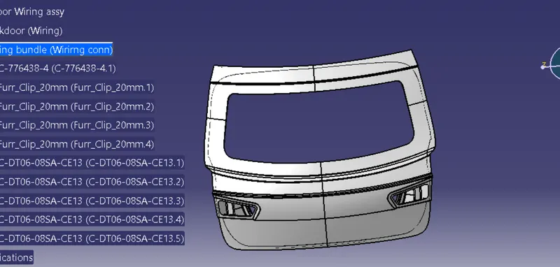
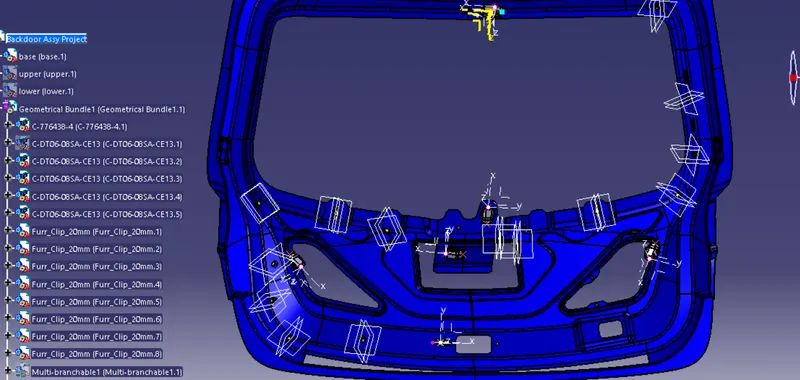
- A Context Assembly for Backdoor Wire Harness has been created, which will work as the main assembly as shown in the figure above.
- A Context Assembly will contain Backdoor Assembly data and Backdoor Wire Harness Geometrical Bundle Assembly.
Step 2: To Define the Connectors
Here, according to the requirement, we are using
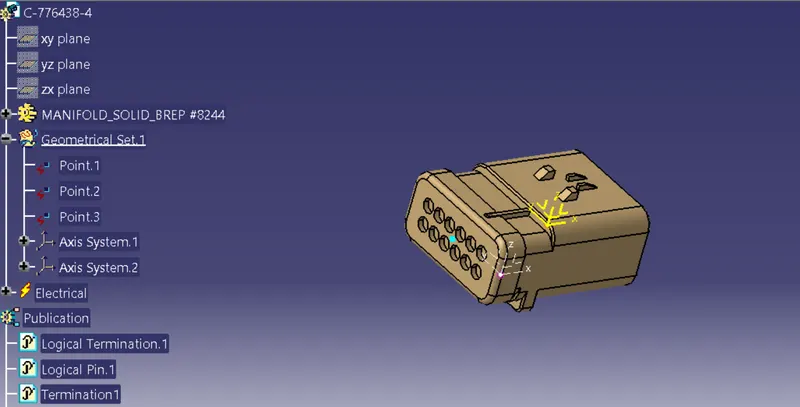
- ‘C-776438’ Which is a 12 Pole connector is used as an inline Connector
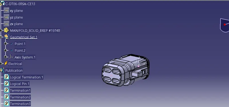
- C-DT06-08SA-CE13which is a 8-pole connector for Taillight
- C-DT06-08SA-CE13which is a 8-pole connector for Number Plate Light
This CAD data was obtained from te.com. To electrically define a connector, we must first define the geometrical parameters such as the bundle connection point and connector connection point in the Electrical Part Design workbench for the downloaded connector.
‘C-776438’
C-DT06-08SA-CE13
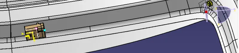
For Supporting clip we used firr tree clip for Backdoor to provide support as well as act as a guiding channel, so we must first define it electrically with geometrical parameters, entry, and exit points on both the left and right sides of the clips, as shown in the figure below
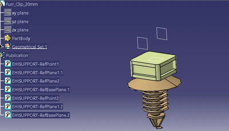
Placement of the Connectors & firr tree clip
Step 4: Bundle Routing:
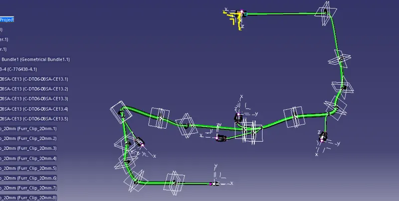
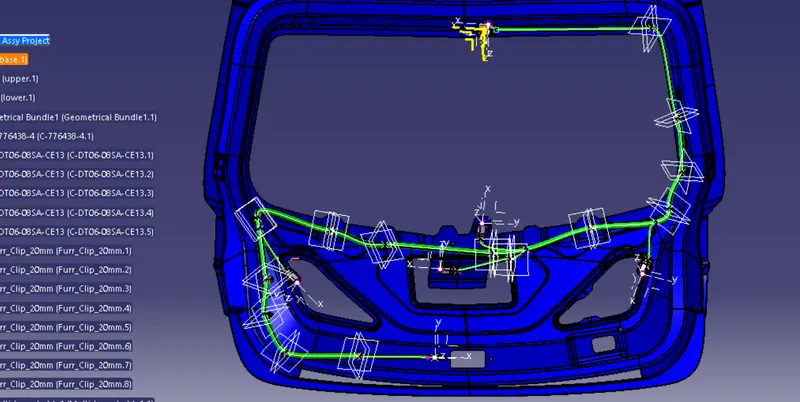
- The bundle segment is routed from the interconnection connector to the Omega clips and guided towards the 4 and 2 Pin connectors. while maintaining the Bend radius ratio of 1.4.
- We have used bundle thickness 15-10mm
Step 5: Checking bundle continuity
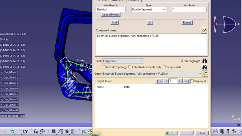
In this step, we must first ensure that multi-branch capability is selected before proceeding to Edit>Search>Advanced>Workbench-Electrical>Type-Bundle Segment>Attribute-Fully Connected.
Selecting 'True' displays all connected bundle segments while selecting 'False' displays all non-connected bundle segments.
In this case, we chose the 'False' option and searched for results. As shown in the figure below, indicating that they are all electrically connected.
Step 6:Adding protective coverings and guiding channels top shell to harness bundle
Here is the below figure, we have done with the whole wiring harness routing for the Backdoor. Now, we have to add protective coverings to all bundle segments
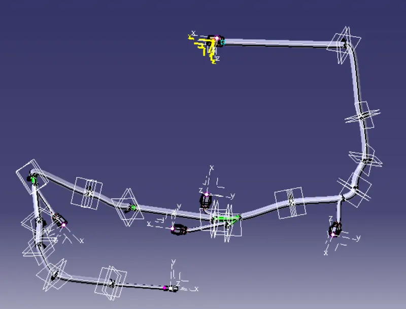
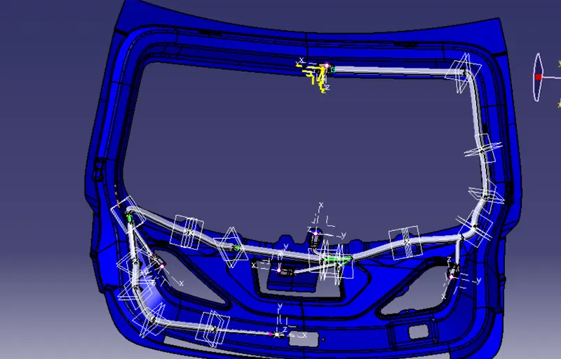
NOTE-while giving protective covering start extremity and enf not showing regarding that i created a session but it seems to software issue
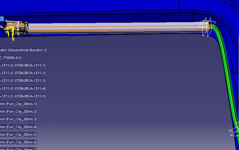 Like this error occurs
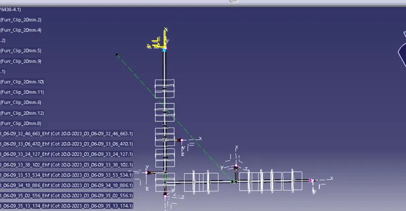
Step 7: Creating flatten view of the Backdoor Wire harness geometrical bundle assembly
In this step, we will use Catia V5's Electrical Harness Flattening workbench to create a flattened view. We should also ensure that the flattening file is saved in the same folder as the other harness assembly files.
- The bundle assembly was extracted into a Back door wire Harness Flattening Product file, which was then flattened along the face of the interconnection connector.
- We developed a flattened view.
- we must rotate bundle segments connecting to the four cam-shaft connectors using the 'Rotate' feature of the flattening workbench.
- It should be noted that the 'face' of the interconnection connector serves as the flattening plane, so we must rotate the bundle segments only along that plane.
- We used various features such as bend, rotate, and roll to streamline the harness for better representation.
The flattened view's final representation
Step 8: Creating a flattened view drawing for the wiring harness assembly
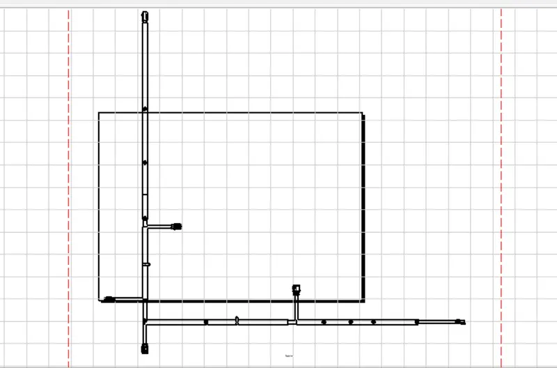
In the figure above, we're creating a new drawing file and defining all of the required drawing parameters. The front view of the Backdoor wire Harness Flattening Product file must be inserted into the Drawing file. As shown in the preceding figure, we must define drawing properties. It should be noted that the 3D wireframe is always ON in the 'Dress up settings. If this option is not enabled, the bundle segments will not be visible in the drawing view. the Backdoor wire Harness Flattens view's final Drawing view
Overall Images of the Assembly