Project 2
Design and Analysis of a Permanent Magnet Synchronous Motor using ANSYS Electronics
Abstract:
This paper presents the design and analysis of a permanent magnet synchronous motor
(PMSM) considering the axial asymmetric PM overhang for a smart actuator (SA) application such as
an isokinetic exercise machine. This structure helps take advantage of the motor space effectively
and makes the system small in size and light in weight. However, two drawbacks related to the
performance of motor occur when the axial asymmetric PM overhang is used: (1) an axial attractive
force (AAF) is created, which can produce motor noise and vibration; (2) the torque of motor is
reduced compared with the symmetric PM overhang model. We used five steps to solve these
problems. Firstly, the AAF according to the variation in axial position of the rotor to the stator was
calculated and analyzed. Secondly, the torque was calculated under the same conditions to confirm
that the system requirements were satisfied. The three-dimensional finite element analysis was used
to determine the AAF and torque. Thirdly, the appropriate axial position of the rotor to the stator
was suggested considering the analysis results and space inside the housing. Next, the commercial
bearing type was chosen so that the total force acting on the bearing was below the bearing load limit
to ensure motor stability. Finally, a prototype model was made and tested to confirm the accuracy
of the analytical results. Through this study, by using the axial asymmetric PM overhang, the total
length of SA was reduced by 5mm and the performance of motor was guaranteed.
Keywords: axial asymmetric permanent magnet overhang; axial attractive force; groove ball bearing
selection; isokinetic exercise machine; permanent magnet synchronous machine; smart actuator
1. Introduction
Smart actuators (SAs) composed of modules integrating an electric motor, gear reducer,
and controller, which are widely developed as driving modules for robots, are used in many applications
to make the compact system. In this study, we examined when SAs are used as an electrical load on
an isokinetic exercise machine (IEM), and described the design and analysis of the electric motor that
constitutes the SA
IEM is a machine that controls the speed of contraction within the range of motion. It is widely
used in rehabilitative activities or sports rehabilitation [1]. The main components of an IEM system
are shown in Figure 1a. The electric load mainly consists of a controller, electric motor, and reduction
gear. Conventionally, the three main components of the electric load are placed separately, creating the
conventional electric load, as shown in Figure 1b. However, since the space for the system is limited,
using a SA type electric load is useful, as shown in Figure 2. The SA module may help simplify the
system structure, improve reliability, and create a compact system [2]. Researchers are interested in the
permanent magnet synchronous motor (PMSM) design for SA module to achieve high efficiency and
high power density, which can be designed using optimal design techniques or the PM overhang to
generate more magnetic flux in the air-gap [3–16]. Most PMSMs use a PM overhang structure in the
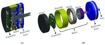
Figure 2. Smart actuator type electric load: (a) cross-section view and (b) close-up view.
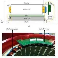
Figure 3. (a) Half cross-section view of brushless PMS ,(b) coil connection and Hall effect sensor
board in brushless PMSM prototype.
The use of PM overhang has a positive effect on the performance of the motor; however,
the asymmetric PM overhang breaks the axial magnetic symmetry of motor and reduces the magnetic
torque. This generates an axial attractive force (AAF). AAF can damage the bearing and create noise
and vibration [5]. Therefore, we investigated the value of AAF according to the axial position of the
rotor to the stator. The torque value is also affected by the asymmetric PM overhang, so we calculated
the torque to ensure that the system requirement was satisfied. Both AAF and torque were determined
using three-dimensional finite element analysis (3-D FEA). Afterward, the commercial bearing was
selected to ensure the stability of the motor. Considering the analysis results together with the actual
dimension of the motor, the appropriate axial position of the rotor to the stator was determined. Finally,
the analysis results were validated by the experiment.
2. Proposed Model Description
Several periodically 3-D analysis models of the PM motor with different rotor core to stator core
positions are shown in Figure 4, in which Dx is the distance between the mechanical centers of the
rotor and stator. The motor is symmetrical when Dx = 0 mm, i.e. the symmetrical model has a 5mm of
PM overhang on both sides. The concentrated winding with the 20-pole and 24-slot model is designed
to have lower end-winding length and lower copper loss. The axial length of the rotor is 10 mm longer
than the stator’s axial length, i.e., 5 mm of PM overhang for each side in the axial symmetrical model.
The design target is to meet the rated torque requirement and obtain high efficiency. Table 1 shows the
output performance requirements and dimensions of the motor.
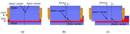
Figure 4. Periodic three-dimensional (3-D) analysis model, when Dx, which is the distance between the
stator center and rotor center, is (a) 0, (b) 5, and (c) 15 mm.
Table 1. Specifications of the analysis model
| Specifications | Value | Unit |
| Output Requrment |
Rated output power (Continuous operation) Maximum output power (Instantaneous operation,30s) Rated speed Rated torque |
1.5 kW 4.5 kW 540 rpm 26.7 rpm |
| Dimensions |
Stator outer diameter Rotor inner diameter Length of stator Length of rotor Air gap |
180 mm 90 mm 90 mm 100 mm 2 mm |
| Cooling type | Natural cooling |
3. AAF Analysis Due to Asymmetric PM Overhang
Due to the asymmetric configuration, the 3-D FEA was used to calculate the AAF values.
The magnetic field can be solved using commercial software (3D Maxwell, ANSYS, Inc., USA).
The virtual work method is used to determine the axial attractive force and magnetic torque [18].
Wmag =
1
2
y B.HdV (1)
AAF =
∂Wmag
∂z
(2)
T =
∂Wmag
∂θ = Fθ × Rrotor (3)
where Wmag is the total stored magnetic energy, B is the magnetic flux density, H is the magnetic field, z
is the axial displacement, Fθ is the force in the θ -direction, and Rrotor is the radius of the outer rotor.
Figure 5 shows the periodical 3-D analysis models of the PM motor. Since the model has a fractional
slot per pole configuration, which is 20-pole and 24-slot, a 1/4 periodic of the machine was modeled
in 3-D FEA. The Neumann boundary condition was applied to reduce the analysis time. The model
with symmetrical PM overhang has a 5 mm on both sides. The air-gap flux density distribution in
both symmetric and asymmetric models is shown in Figure 6. In the case of the symmetric model,
the air-gap flux density is distributed symmetrically on both sides of the overhang region. In contrast,
the asymmetric model generates asymmetrical flux, which produces AAF and motor vibration.
4. DESIGN METHODOLOGY
The design involves an RMXPRT model of the BLDC motor.
The permanent magnets are embedded in the laminations inside
the rotor slots while the poly-phase armature winding is
embedded in the stator whose number of poles is the same as
that of a rotor. The stator poly-phase winding is connected to a
power supply that is D.C in nature. The connection is made
through a switched circuit to produce a rotational magnetic field
in the air gap. The conduction sequence of the switched circuit
depends on the position of the rotor magnetic field. The attempt
is to make the stator magnetic field orthogonal to the rotor
magnetic field. The function of the switched circuit is the same
as the commutator in the conventional dc electric machine.
4.1 RMXPRT model – ANSYS Electronics
Table 1: Model design parameters
Parameters Motor Design
Number of Poles 8
Types of magnets embedded
Number of Winding 3
Number of slots 48
Rotor position I nner rotor
Transistor & Diode drop 0.8 V
Load angle or trigger 0
Voltage 240 V
Rated speed 4000 RPM
Rated current 18 amps
Efficiency 96%
4.2 Design Flowchart
The process initiates with specifying the design aspects of the
motor allocating the poles in stator and rotor and setting up the
voltage and input current. The setup is followed by entering the
value for motor dimensions i.e. stator and rotor inner and outer
diameter. Slots and winding types are entered and the value of
air gap length follows. The selection of magnet is important for
better conduction and high strength magnetic field. Some of the
used magnets are Ferrite, Alnico, Samarium Cobalt, and
Neodymium Ferrite Boron. Once we input the values, a solution
setup needs to be set up with values of rated voltage, rotational
speed and operating temperature of the motor. This is followed
by the analysis and results
Design Specification
Rotor, stator specification
Dimension of the motor
Slots and winding type
Air gap length
Winding factor
Magnet selection and positioning
Solution setup
Analyze
Fig. 1: Design flowchart
Table 2: Stator specification
Parameters Motor design-stator (inch)
Outer Diameter 8
Inner Diameter 5
Length 4
Stacking Factor 0.93
Steel type M19-24G
Number of slots 48
Skew Width 0
Number of branches 3
Table 3: Rotor specification
Parameters Rotor Specification (inch)
Outer Diameter 4.75
Inner Diameter 1.5
Length 3.8
Steel M19 -24G
Stacking factor 0.93
The model of the IPM BLDC motor was made in ANSYS
electronics suite and later the FEA simulation is carried out in
MAXWELL 2D.
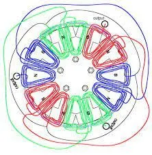
Fig. 2: Connected stator coil setup
The stator coil was not connected during the analysis stage. The
diagram just shows the coils connected in the designing phase
when the values to stator slots and coil pitch were allocated
The values taken are as follows: (Inch)
Tooth width – 0.042*1.2
Hs0 -0.028
Hs2 – 0.72
Bs0 – 0.080
The parallel arrangement of a tooth is selected with whole-coiled
windings. The number of slots on the winding is taken as 28.
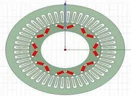
Fig. 4: IPM BLDC motor setup RMXPRT model
The value of the rotor pole parameters are as follows: (inches)
Embrace - 0.7
Bridge – 0.05
Rib – 0.5
Magnet – NdFe30
Magnet width – 0.5
Magnet thickness -0.15
The values used in solution setup –
The parameters used for the solution setup are as follows:
Load type – constant power
Rated horsepower – 10 HP
Rated voltage – 356 V (240 *pi*sqrt (2)/3)
Rated speed – 4000 RPM
Operating temperature – 75 Celsius.
Based on the solution set up an analysis of the DC machine is
carried out which provides no-loaded, full –load and steadystate value of the electric parameters.
5. OBSERVATION
Based on the analysis of the RMXPRT model of the IPM BLDC
motor setup the following results are obtained:
Now to carefully asses the dependency of these results on certain
parameters another solution setup is added and certain changes
were brought in the design.
The design changes include:
• The control type is changed from D.C type to Chopped
current control (CCC).
• Maximum current = 20 Ampere and minimum current = 18
Ampere.
• The orientation of the winding is changed and the coil pitch
is changed from 3 to 7.
• Slot value of stator set to 9.
• The slot figure modified.
• Number of strands in the machine set to 1 from 0
• Rib -0.5, Bridge – 0.1
The intention is to measure the variation of the torque and power
characteristics curves with variation in the air gap between
magnets and certain winding changes.
Modified RMXPRT model:
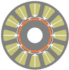
Fig. 7: Modified Design of IPM BLDC motor
6. COGGING TORQUE ANALYSI
The torque present due to the interaction between the permanent
magnet of stator and rotor slots in an IPM BLDC machine is
known as cogging torque. The presence of cogging torque in
addition to the electromagnetic torque and reluctance torque
induces vibration, acoustic noise, speed ripples, and position
inaccuracy, which hampers the motor performance at low
speeds and low loads.
In order to accurately calculate the value of cogging Torque, the
process followed involves solving a parametric sweep in
Magnetostatic (the input parameter being the angle between
rotor and stator). The method adopted might not lead to excellent
results, as the error due to the mesh will be different for each
position (the mesh will change for every row).
Therefore, the steps followed will have a particular sequence
and it will be carried out in accordance with the design presented
in the initial stage. Another approach that is preferred in this
research is by using a transient solver with motion. In the
simulation process, the rotor is moved at the speed of 1 degree/s.
Therefore, the mesh remains unchanged for all the positions due
to the Band object: the mesh inside the Band object will rotate
with the rotor. Due to this, each time step will be independent of
the other. The adaptive mesh will not be used therefore the
simulation time will be shorter.
STEP 1: Simulation at NO –LOAD
The meshing operation and calculation setup of the analysis of
the motor at full-load are done. To carry out this operation in
ANSYS electronics a MAXWELL 3D model of the motor is
made and static and dynamic analysis is carried out with
appropriate input parameters and master-slave and Vector
potential boundary conditions.
The Maxwell model is first reduced in size for adaptive meshing
and application of initial boundary conditions. This resulted in a
plot of magnetic flux strength highlighting the magnetic flux
densities at all faces of the rotated motor setup.
simulation time will be shorter.
STEP 1: Simulation at NO –LOAD
Fig. 11: Maxwell Design with Lap coil arrangement
The meshing operation and calculation setup of the analysis of
the motor at full-load are done. To carry out this operation in
ANSYS electronics a MAXWELL 3D model of the motor is
made and static and dynamic analysis is carried out with
appropriate input parameters and master-slave and Vector
potential boundary conditions.
The Maxwell model is first reduced in size for adaptive meshing
and application of initial boundary conditions. This resulted in a
plot of magnetic flux strength highlighting the magnetic flux
densities at all faces of the rotated motor setup.
Fig. 12: Cut section for electrical simulation
Fig. 13: Magnetic flux density at the face of the cut-section
The model highlights the maximum value of the magnetic flux
density obtained at the face of the magnet at a no-loaded
condition. However, for cogging torque, we are considering the
solution setup of full –load motor condition with variations in
the calculation.
STEP -2 Variation in FULL-LOAD DATA:
• The rotor is moved at 1 Degree/sec.
• One pole pair takes 7.5 mechanical degrees.
• Solving over 15 in order to have two periods.
• The time step is set to 0.125 s to have a very smooth curve.
• Lowering the nonlinear residual to 1e-4.
Selecting the parameters to a plot that involves torque and time
we get a curve showing the value of cogging torque relevant to
this design i.e. 1.82 Nm.
The cogging torque can be expressed by the integration of the
normal and tangential magnetic flux components within the air
gap. [1]. We can also consider this design aspect of the machine by
relating the parameters of pole shoe variation and magnetic
span angle to the cogging torque.
7. CONCLUSION
The research paper covers all the aspects pertaining to the
designing and solution-based analysis of an Interior permanent
magnet DC brushless motor. It also assesses the performance of
the motor and the dependency on the positioning of rotor
magnets. The variation of torque and induced phase voltage by
the change in the magnet width and spacing is highlighted with
performance curves. A major discovery would be the reduction
in air gap flux density and cogging torque with changing rib and
bridge in the rotor slots.
In addition, the simulation with full-load data in ANSYS
electronics suite with the objective of calculating the cogging
torque was successful and thus by reducing the angular speed of
the movement of the rotor along with keeping a smaller time
step resulted in a complete simulation with the lesser error.
However, many aspects of motor design and performance
testing are untouched by this paper due to a lack of information
and resources. The non – availability of funds and limited access
to the labs have limited my research to only computer designing.
Therefore, a lot of further progress could be made and a variety
of design approaches can be tested to assess the performance of
an IPM BLDC motor.