Project 2
Automotive Wiring Harness for Backdoor
Aim: To create a Wiring Harness for the Backdoor,Flatten the same for the production and apply the neccsary protective covring using CATIA V5 software.
Objective: The objective is to route the wiring harness for the backdoor and flatten the wiring harness to Drawing for the representation. By Considering proper Packaging rules and Industry Based practices are consired while routing the wiring harness. In this harness, we should have to consider the necessary Rules for clearence, selection of clips and Connectors and Check for Bundle continuity.
Introduction
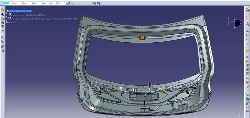
The cover over the primary baggage compartment or storage area is called the trunk lid. The lid may be lifted thanks to hinges. The panel can be maintained in the open position using tools like a manually adjusted prop rod. The trunk lid can also be raised and held open with the assistance of counterbalancing torsion or other spring(s). There may be a third brake light positioned in the centre of the trunk lid on vehicles with a rear-mounted trunk. A decorative air spoiler may also be present on the back lid. The key fob for the vehicle may be used to release the trunk lids of many current vehicles.
Together with the passenger compartment, the trunk may be locked.
The trunk may sometimes be opened remotely in some vehicles. This can be done in a number of ways, including:
- The trunk opens after the latch is released, possibly hiding the opening under the lid when the door seals push the decklid away from the lock.
- The trunk opens once the latch is released, revealing the opening when the decklid is pushed away from the lock and away from the opening.
- The trunk is opened once the latch is released and a drive, either hydraulic (BMW 7 Series) or electric (BMW X6), is activated to push the decklid away from the lock. The lid then lifts to show the opening. Then, this might be electrically closed once more.
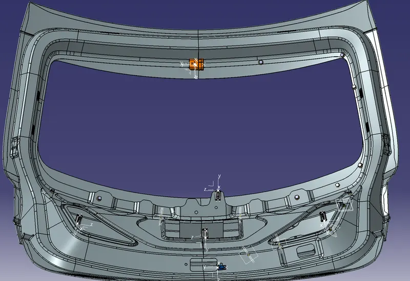
Fig. Backdoor/Trunklid
Rules to be followed to route the Harness
- Easy manufacturing, installation, removal and maintenance needs to be addressed in designing the wire harness.
- It is important to route the wiring harness so that it is simple to install and access.
- The area around a wiring harness should be free of sharp objects like corners and edges.
- When assembling or servicing a harness, avoid routing and clipping in regions that are difficult to access or in blind spots.
- If more slack is required due to the environment or the harness bending requirement, give it. The envelope dimensions during door opening and shutting should be taken into consideration to allow slack if the harness is going through the closures/doors or tail gates. Here the slack should be between 1 to 5mm.
- When designing the wire harness in the CAD environment, it is important to ensure that there are no instances of fouling. To prevent fouling, additional mounting tools like clips or clamps may be employed.
- Avoid passing through tiny structural apertures and holes. to reduce handling and chaffing when installing the wire harness.
- Use of rubber grommet is recommanded if harness is passing from wet zone to dry zone of Vehicle.
- The branch length should be greater than 50mm.
- The distance between the clip and connector should be more than 25mm.
- The distance between the two branch points should be greater than 50mm.
- Clips/clamps used for the wiring harness should be easily available in the market to avoid extra cost for custom mounting solutions.
- Before routing the componet all the neccessary parts like connctors, clamps, clips and Bacshell should be electrically defined.
- Check for the bundle continuity.
- Keep harness away from Transmission dynamic assemblies like Drive shaft or propeller shaft.
- Limit the number of branches from single branching point to 4.
Coceptual Harness Routing
Here I have considered the connectors for power supply, Tail lights, Clutch, Number plate and Wiper
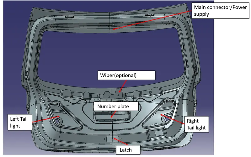
Steps carried out in the catia v5 are as follows,
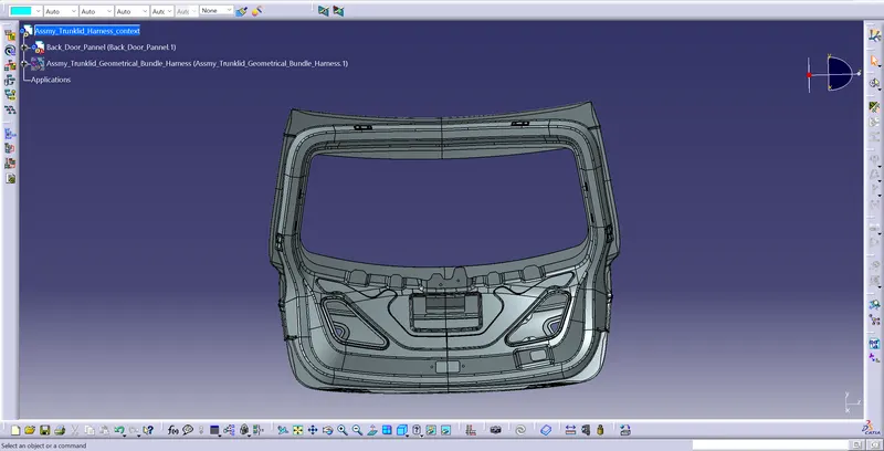
- Fist download the backdoor catia part from the challenge Dashboard, save the compnent and copy the part in the Assembly context is shown in the fig,
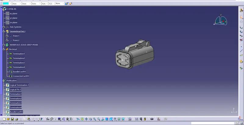
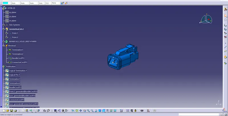
- Download the C-776438, C-DT06-4S, C-DT06-2S Connectors from www.te.com and Define it as electrically using Electrical part design and copy under Assmy harness bundle
C-776438
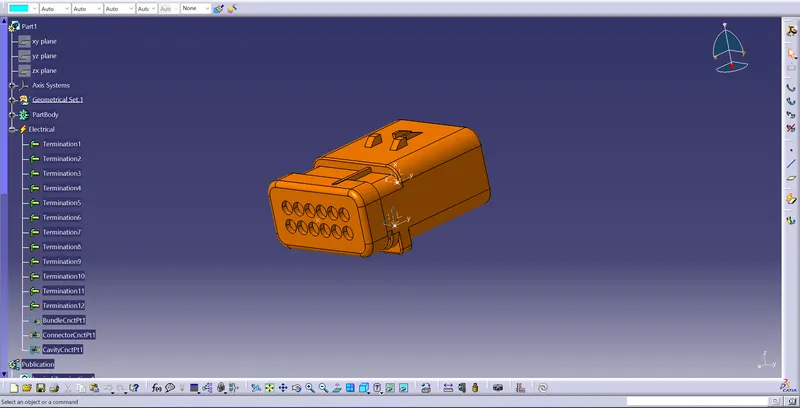
C-DT06-4S
C-DT06-2S
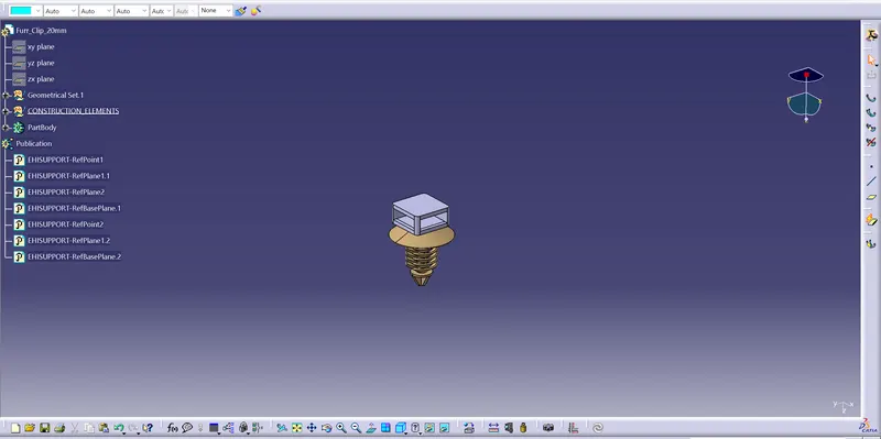
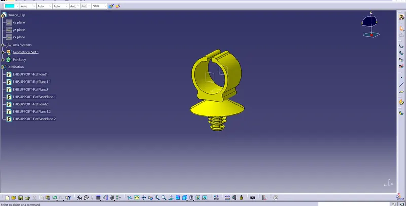
- The clips used are Furr-tree clip and Omega clip and it should be electrically defined
Furr-tree clip
Omega clip
- Place all the connectors and clips on the Backdoor pannel using manipulate, snap and smart move tools in the Assembly Design
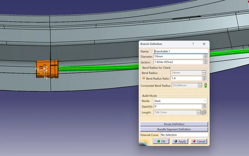
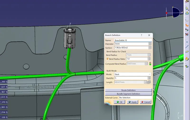
- Next is to Bundle harness to the connectors and clips using Electrical Harness Assembly and Main branch diametr is 10mm and Sub-Branch is 5mm diameter.
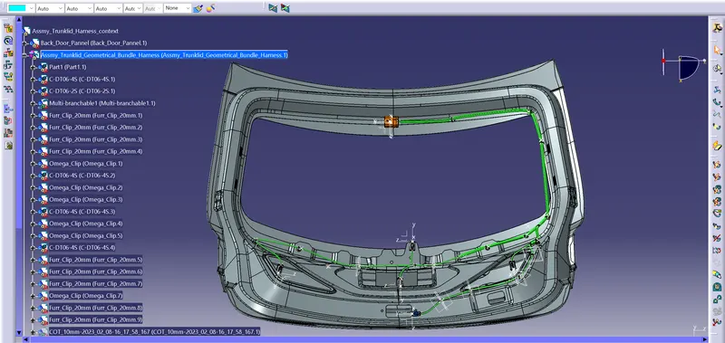
- Add Protective covering to the Bundle for protection and it also absorbs vibrations of 15mm and 10mm from the catalog.
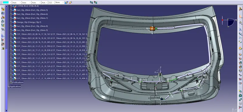
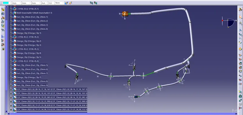
- Check for the Bundle Continuity, Select the neccessary options as shown in the fig.
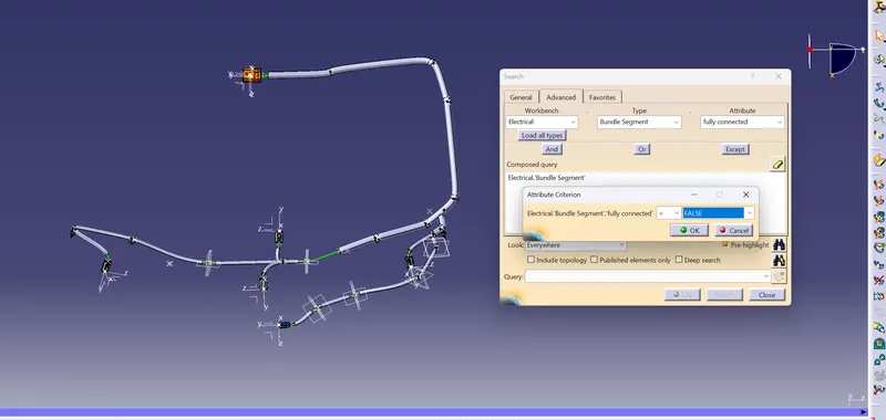
Click ok and click the Binocular icon(First)
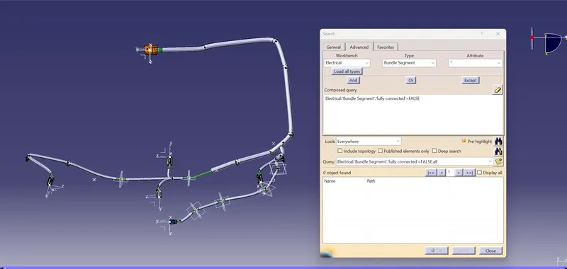
- Then the Bundle harness is flattened from 3D model to 2D model using Electrical Harness flattening workbench.
- Use the Harness flattening parameters option to give neccessary parameters for easier Bundle flattening and sis shown in the below fig
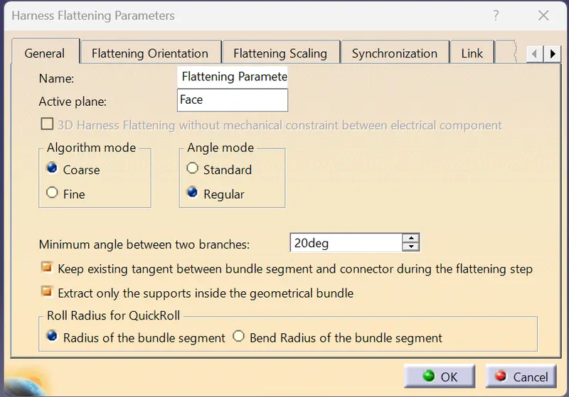
- Next, use the extract tool and select the Geometrical Bundle product file from Context assmy file and It will create Ehf file.
- Then click the flatten option and shown in the below fig.
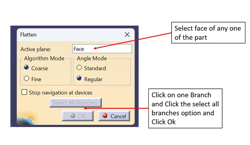
- Using tools like Rotate, Roll and Scale to create desired flattening
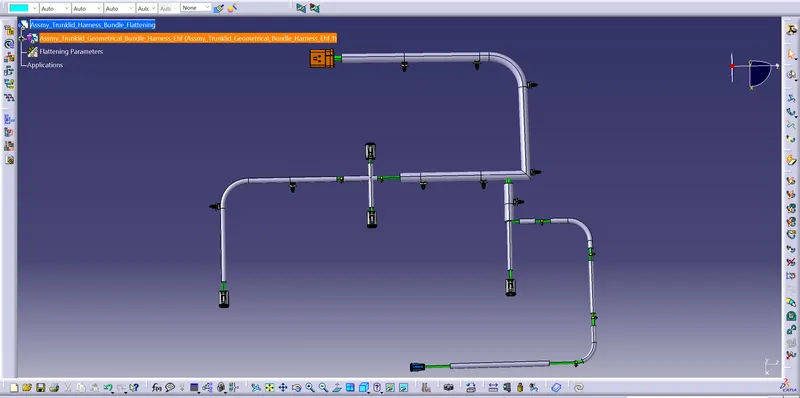
- The final step is to create a Drawing sheet to represent 2D model for production purpose.
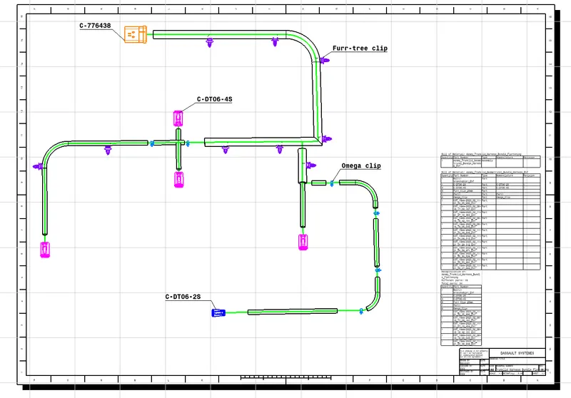
- Save all the product files in one main file by using save management option.
Visualiation of the Product