Project
Your Answers
1.AIM:-
To propre to technical report of simulation of BAJA ALL-TERRAIN Vehicle(ATV) Under different conditions.
SOFTWARE:
1)MATLAB
2)Simulink
3)Simscape
4)Simscape Driveline
ABOUT THE MODELS:-
These models show how to build an ATV with CVT which is mostly used in BAJA competitions. Simscape and Simscape Driveline have been used to complete the system. The engine data used in the model is provided as an image which shows the Engine Speed (RPM) Vs Torque curve.
OBJECTIVES:-
1).study the baja ATV with CVT model .
2).study the baja ATV with CVT model with dashboard.
3).study the baja ATV with CVT model using lookup table.
4).study the baja ATV with CVT model using lookup table with dashboard.
ALL TRERRAIN VEHICLE:
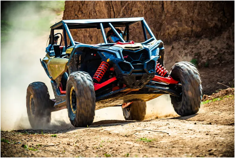
Major Components of ATV:-
*vehicle Body
*suspension
*tire
*engine
*Continuously Variable Transmission.
If a vehicle is described as an all terrain vehicle, it usually has four-wheel drive, high ground clearance and the big tyres needed to tackle . An ATV can go places that a road car can’t: fields, hills, rocks, rivers, mud
CVT TRANSMISSION:-
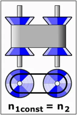
The Components of CVT:
*primary pulley
*variator
*secondary pully
*Belt
A continuously variable transmission (CVT) is an automatic transmission that can change seamlessly through a continuous range of gear ratio. This contrasts with other transmissions that provide a limited number of gear ratios in fixed steps. The flexibility of a CVT with suitable control may allow the engine to operate at a constant RPM while the vehicle moves at varying speeds.
Condition:
1.The primary pulley moves inward while the secondary pulley moves outward then it will lead to overdrive.
(Rp>Rs)
2.The primary pully moves outward and the secondary pully moves inward then it will lead to speed Reduce.
(Rp<rs). < p=""></rs). <>
STUDY1:-
The model is Contains Simscape model of BAJA ATV with Continous Variable Transmission.
Figure-1
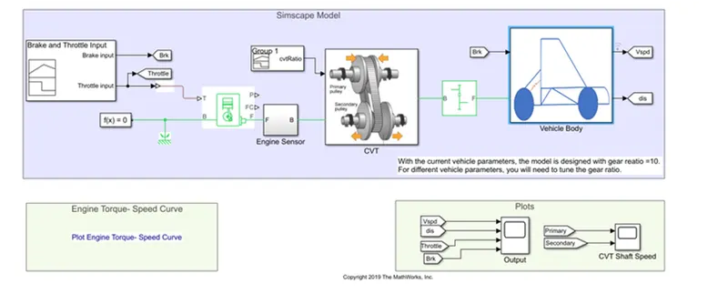
The simscape model of CVT consists of Signal builder and generic engine,ideal motion sensor,vehicle transmission,simple gear vehicle body, tyres and solver configuration block etc...as shown in figure -1.T
CVT MODEL USING BLOCK:
SIGNAL BUILDER:
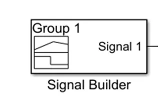
The Signal Builder block allows you to create interchangeable groups of piecewise linear signal sources and use them in a model. You can quickly switch the signal groups into and out of a model to facilitate testing. In the Signal Builder window, create signals and define the output waveforms.
The model ,there are two inputs give is Barke and throttle
GENERIC ENGINE:
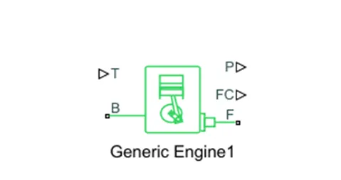
*The Generic Engine block represents a general internal combustion engine. This block is a suitable generic engine for spark-ignition and diesel. Speed-power and speed-torque parameterizations are provided. A throttle physical signal input specifies the normalized engine torque. Optional dynamic parameters include crankshaft inertia and response time lag.
*Generic engine T will connected for the throttle and B will the connect the mechanical Rotational Reference.
* F connected the engine sensor
SIMPLE GEAR:
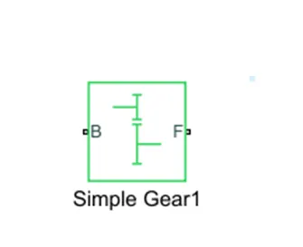
The Simple Gear block represents a gearbox that constrains the connected driveline axes of the base gear, B, and the follower gear, F, to corotate with a fixed ratio that you specify. You choose whether the follower axis rotates in the same or opposite direction as the base axis.
VEHICLE BODY:
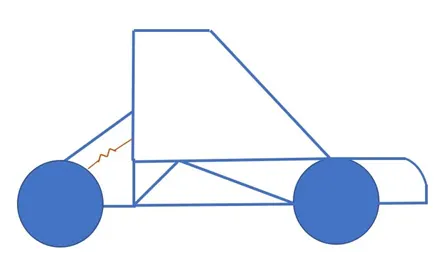
The Vehicle Body block represents a two-axle vehicle body in longitudinal motion. The vehicle can have the same or a different number of wheels on each axle. For example, two wheels on the front axle and one wheel on the rear axle.
FROM & GOTO BLOCKS:
FROM:
The From block accepts a signal from a corresponding Goto block, then passes it as output. The data type of the output is the same as that of the input from the Goto block. From and Goto blocks allow you to pass a signal from one block to another without actually connecting them.
GOTO:
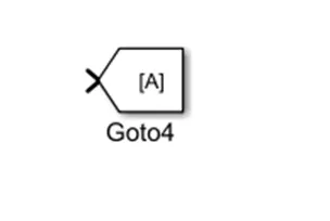
The Goto block passes its input to its corresponding From blocks. The input can be a real- or complex-valued signal or vector of any data type. From and Goto blocks allow you to pass a signal from one block to another without actually connecting them.
Solver Configuration:
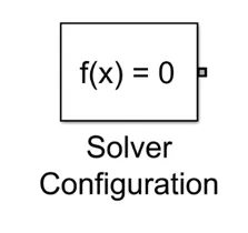
Each physical network represented by a connected Simscape block diagram requires solver settings information for simulation. The Solver Configuration block specifies the solver parameters that your model needs before you can begin simulation.
Each topologically distinct Simscape block diagram requires exactly one Solver Configuration block to be connected to it.
SCOPE:
The scope block use to displaying the result in graphical wave from.
CVT SUBSYTEM BLOCKS:
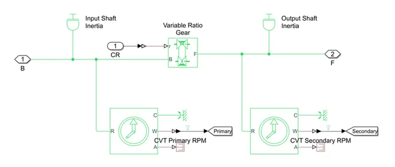
Figure-2
The CVT subsystem includes transmission block ,input and output shaft inertia and motion sensor as shown in figure-2.T
VARIABLE GEAR TRANSMISSION:-
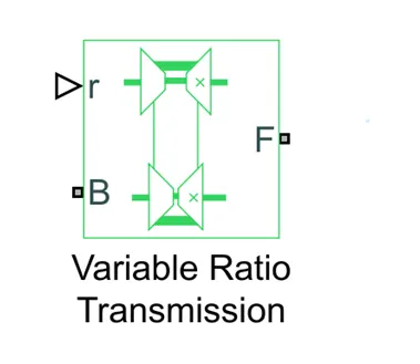
The Variable Ratio Transmission block represents a gearbox that dynamically transfers motion and torque between the two connected driveshaft axes, the base and the follower.
When you choose to have the block ignore the dynamics of transmission compliance, it constrains the driveshafts to corotate with a variable gear ratio that you control. You can choose whether the follower axis rotates in the same or opposite direction as the base axis. If the follower and base axis rotate in the same direction, ωF and ωB have the same sign. If the follower and base axis rotate in opposite directions, ωF and ωB have opposite signs.
INERTIA:
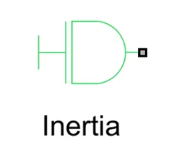
The Inertia block represents an ideal mechanical translational inertia that is described with the following equation:
T=Jdωdt
where:
- T is inertia torque.
- J is inertia.
- ω is angular velocity.
- t is time.
INPORT:
Inport blocks link signals from outside a system into the system.
IDEAL ROTATIONAL MOTION SENSOR:
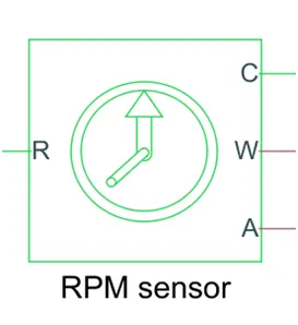
The Ideal Rotational Motion Sensor block represents an ideal mechanical rotational motion sensor, that is, a device that converts an across variable measured between two mechanical rotational nodes into a control signal proportional to angular velocity or angle.
PS -simulink converter:
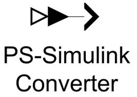
The PS-Simulink Converter block converts a physical signal into a Simulink output signal.
Simulink -ps converter:
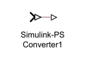
The Simulink-PS Converter block converts the input Simulink signal into a physical signal.
Mechanical Rotational Reference:
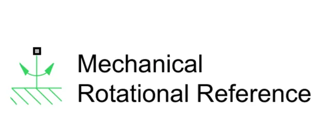
The Mechanical Rotational Reference block represents a reference point, or frame, for all mechanical rotational ports. All rotational ports that are rigidly clamped to the frame (ground) must be connected to a Mechanical Rotational Reference block.
PS TERMINATOR:
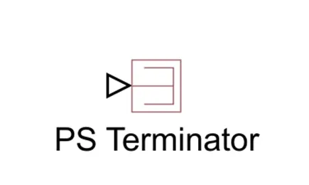
Use the PS Terminator block to cap physical signal output ports that do not connect to other blocks.
VEHICLE BODY SUBSYSTEM:
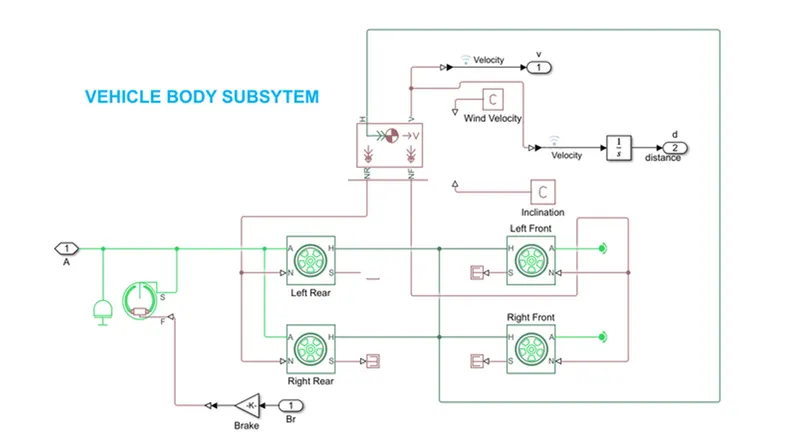
Figture-3
The vehicle body subsytem includes vehicle body block ,double drum brakes and tyres in as shown in figure-3.The initial engine speed is given as 2100rpm,mechanical rotation for driven pulley and driver pulley as 0.8 &.0.7respectively.The mass of the vehicle as 250kg and 2 axles which connects 4 wheel accordingly.
Vehicle Boad Subsystem block:-
Double-shoe Brake:
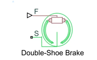
The Double-Shoe Brake block represents a frictional brake with two pivoted rigid shoes that press against a rotating drum to produce a braking action. The rigid shoes sit inside or outside the rotating drum in a diametrically opposed configuration. A positive actuating force causes the rigid shoes to press against the rotating drum. Viscous and contact friction between the drum and the rigid shoe surfaces cause the rotating drum to decelerate.
Tire (Magic formula):
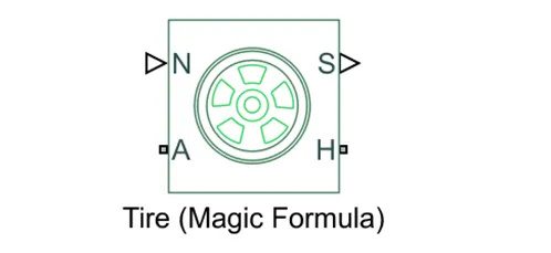
The Tire (Magic Formula) block models the tire as a rigid wheel-tire combination in contact with the road and subject to slip. When torque is applied to the wheel axle, the tire pushes on the ground (while subject to contact friction) and transfers the resulting reaction as a force back on the wheel. This action pushes the wheel forward or backward. If you include the optional tire compliance, the tire also flexibly deforms under load.
Rotational Free End:
The Rotational Free End block represents a mechanical rotational port that rotates freely, without torque.
PS Constant:
The PS Constant block generates a physical signal of a constant value. You specify the value and unit of the signal as the Constant parameter.
Intergator:
The Integrator block outputs the value of the integral of its input signal with respect to time.
INPUT:-
*The signal builder is used as input for Brake,Throttle and Gear Ratio.
*Brake input is maintained as 0 for overall simulation.
*The throttle input is given as 0.3 for 20sec and increases to 1 for overall simulation. And change the other one throttle input 0.5 in 20 sec increase to 1 for overall simulation.
*The throttle value is mainly to control the flow or amount of fuel into the engine ,if the throttle value increases the flow of fuel increases to the lC engine which in turn increases the power of engine.
*The input of Brake ,Throttle and Gear Ratio as shown Figure (4,5,6).
BRAKE AND THROTTLE INPUT:-
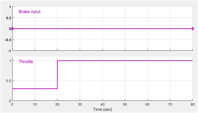
FIGURE-4
Brake will be 0 overall simulation and throttel given value of 0.3 (20 sec) and increase 1 for overall simulation.
AND CHANGE THE VALUE INPUT:
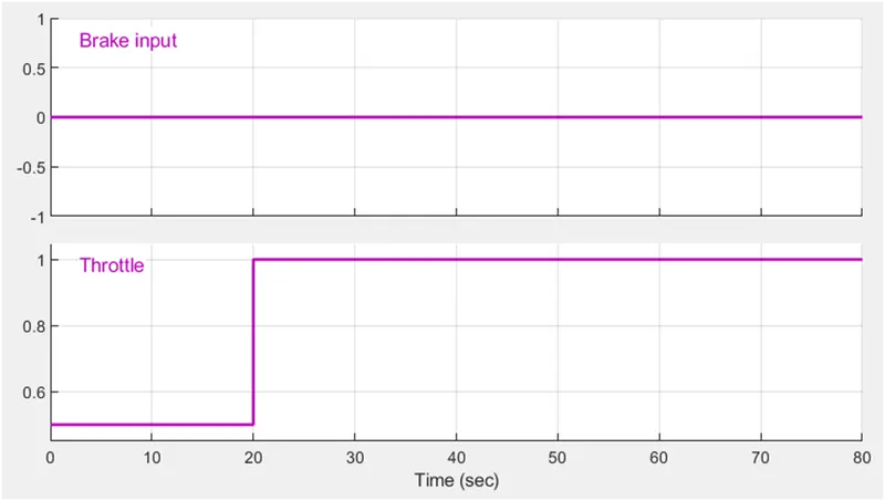
( FIGURE:-5)
Brake will be 0 overall simulation and throttle given value of 0.5 (20 sec) and increase 1 for overall Simulation
CVT Ratio:-
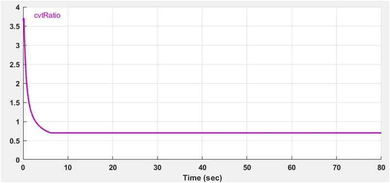
(FIGURE:-6)
Engine Torque -Speed Curve:
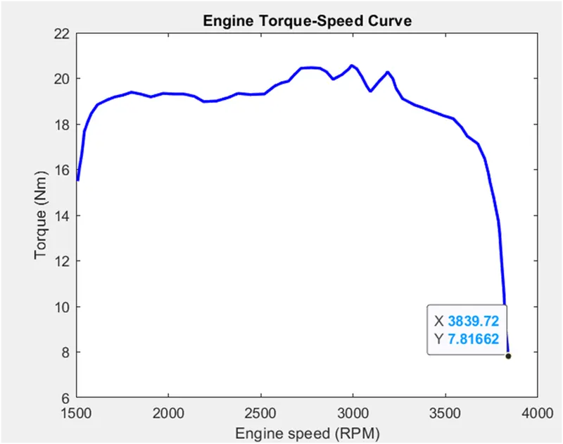
Figure-7
CVT Ratio affects vehicle speed. The GRABIT is used to extract data points and feed them to the workspace's engine. We can calculate the maximum speed and velocity from the aforementioned graph, which is 3839.72.
THE MAXIMUM SPEED OF THE VEHICLE (RPM)=3839.72
SUTDY. 1-RESULT:-
Figure-8
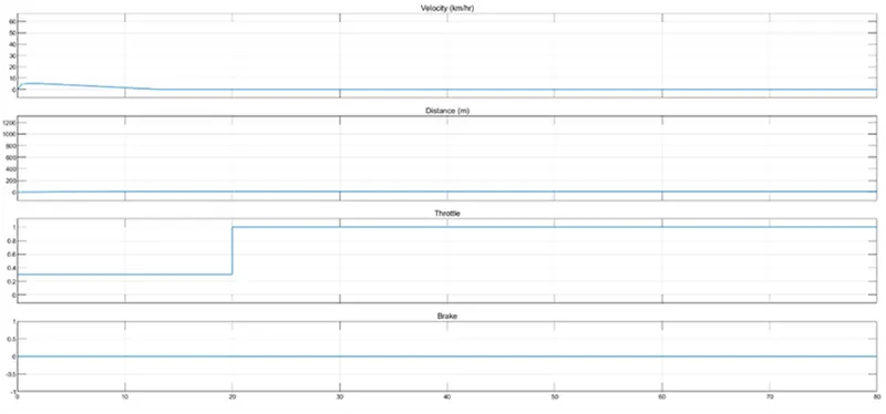
Figure-8
When applying throttle, we noticed that if the value 0.3 is taken into acct, the velocity exhibits a dramatic reduction in speed. Therefore, we changed it to 0.5 for a 20-second total simulation in order to obtain a smooth velocity flow. It is shown in (figure-8,9).
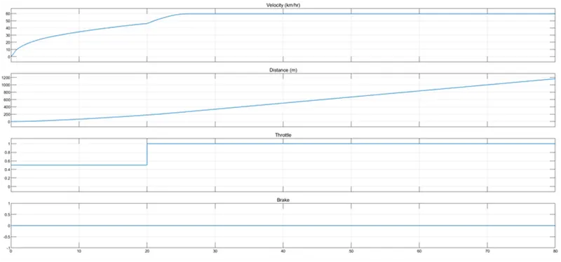
Figure-9
The brake is kept at a constant setting while the throttle is increased to show an increase in velocity. When the throttle is opened to 0.5 for 20 seconds in a simulation, the flow of fuel increases, increasing the engine's power. The gear ratio is directly proportional to the torque once the torque reaches about gear Ratio. This gear ratio allows for the maximum speed and velocity.
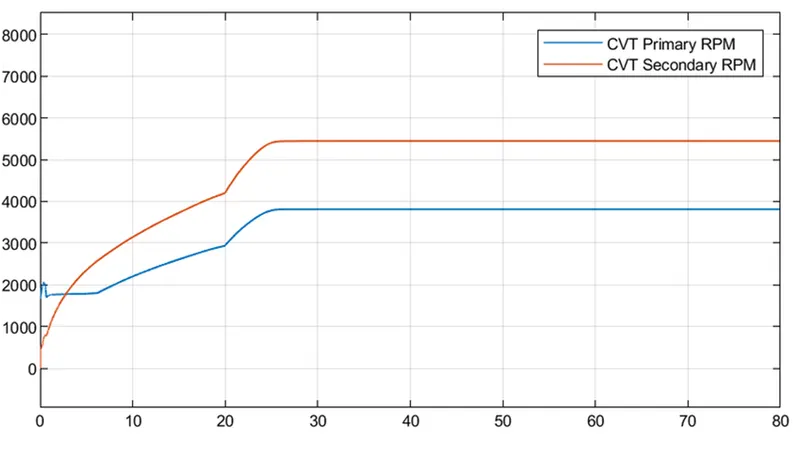
Figure-10
These graphs shown the variation in angular velocity of input and output shafts of the variable gear transmission system .These value differ with respect to the gear ratio.
STUDY-2:-
SIMULINK MODEL FOR BAJA ATV WITH CVT USING DASHBOARD:-
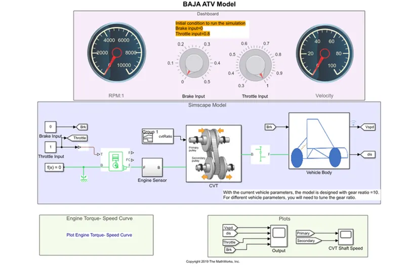
Figure-10
The above figure show "Baja ATV in CVT model with dashboard "model which consists throttle and brake input in the dash board instead of given in through constant block and signal builder .Rest of the blocks and subsystems are common in the above baja ATV model without dash board as shown in( figure 2&3). The main concept of using dash board is study the result varying the input of brake and throttle, which shown that velocity and speed of the engine. The Gear ratio as per maintained the same value shown the figure-6
CONSTANT:-
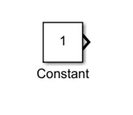
The Constant block generates a real or complex constant value signal. Use this block to provide a constant signal input.
GIVEN INPUT VALUE:-
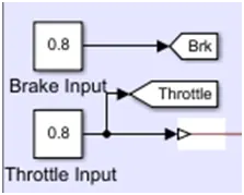
*As the brake input give from 0.8, and throttle value give 0.8 the velocity and speed decreases accordingly.
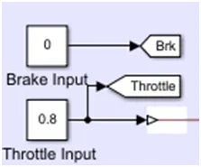
*And change to value of throttle value 0.8 and reduce the brake value 0 .it will be increase the velocity and speed of the engine &shaft increases.
RESULT:-
Givenytyvalue input : Break-0.8 and Throttle-0.8
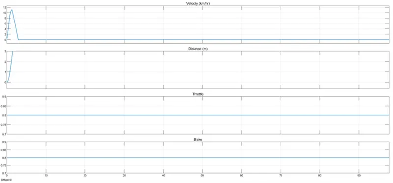
Figure-11
In the above figure, given the throttle value 0.8 given then increasing the velocity apply break value 0.8 then decreasing value of velocity constant and maintain tha 0 value overall simulation

Figure-12
In the above figure, given the throttle value 0.8. and Brake value is 0 Run the constant value. the velocity linearly increase and maintain the constant.
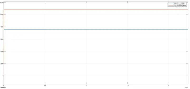
Figure-13
In the above figure ,the primary shaft speed increase by increasing throttle and decreasing by increasing brake input value ,which defines that the throttle can flow more amount of fuel which increases the power of the engine .the radius of the secondary shaft as more the primary shaft .as the radius increases the speed of the also increases.
STUDY-3
SIMULINK MODEL FOR BAJA ATV WITH CVT USING LOOKUP TABLE WITHOUT DASHBOARD:-
By using simulink model
of CVT consists of step time , generic engine , Engine sensor , vehicle transmission ,vehicle body ,tyre and solver configuration blocks etc..,as shown in figure-14. The CVT subsystem includes look up table transmission block, input and output shaft inertia and motion sensor ,as shown in figure-15.The vehicle body includes vehicle body block as shown in figure -16.The initial engine speed is given as 2100rpm , mechanical rotation for driven pulley and driver pulley as 0.8 &0.7 respectively .The mass of the vehicles 250kg and 2 axles whichare connect 4 wheel accordingly.
A look up table is an array of data that input values to output value ,there by approximating a mathematical function.Given a set of input value , a look up operation retrieves the corresponding output value from the table .
GRABIT:-
Its use to extract tha data point and feed in the engine.
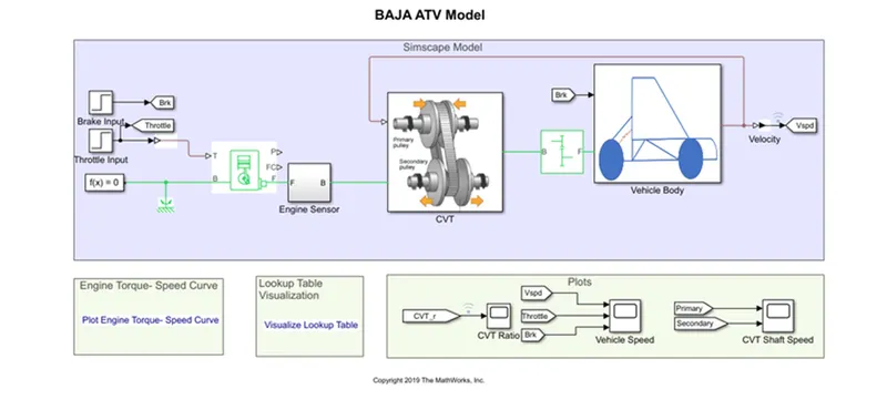
FIgure-14
STEP SIGNAL:
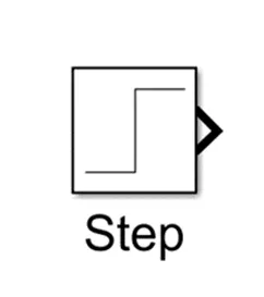
*The Step block provides a step between two definable levels at a specified time. If the simulation time is less than the Step time parameter value, the block's output is the Initial value parameter value. For simulation time greater than or equal to the Step time, the output is the Final value parameter value.
*Step signal given input of the brake and throttle.
CVT Subsystem Block :-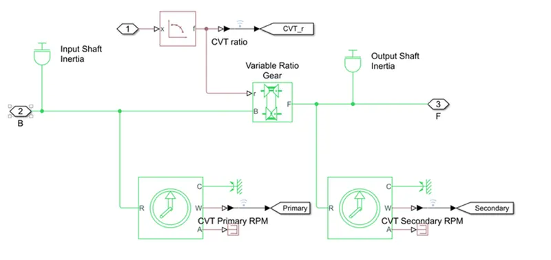
Figure-15
Figure-15
1D LOOKUP TABLE:
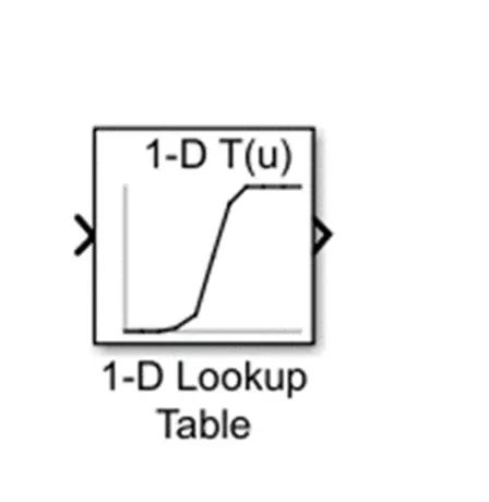
. The block maps inputs to an output value by looking up or interpolating a table of values you define with block parameters. The block supports flat (constant), linear (linear point-slope), Lagrange (linear Lagrange), nearest, cubic-spline, and Akima spline interpolation methods. You can apply these methods to a table of any dimension from 1 through 30.
lookup table feed input data in variable gear ratio.
Vehicle Body subsystem:-
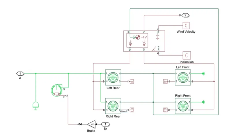
Figure-16
The brake input and throttle input is given by step time ,which depend on the run time and varies accordingly. by using lookup table for gear ratio which take as input to the CVT and works accroding to the input gear ratio and obtained the output .the method is very effective which can avoid the unusual torque at the certain speed and easy to achieve greater velocity &engine speed. it works as closed loop when the input is given by lookup table.the simulink get the input value from lookup table and obtain the result according to the input values of gear ratio.the maximum velocity reached as 66 kmph approximately.
Given Input :
Throttle-0.5 20 sec to 1 constant over simulation.
Brake=0 for 0 sec overall simulation.
Result:-
Lookup Table:
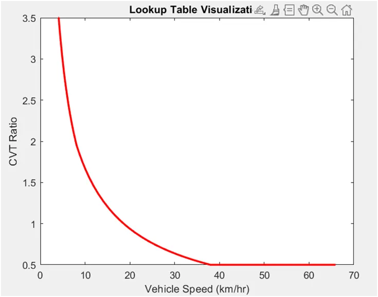
Figure-17
CVT RATIO:-
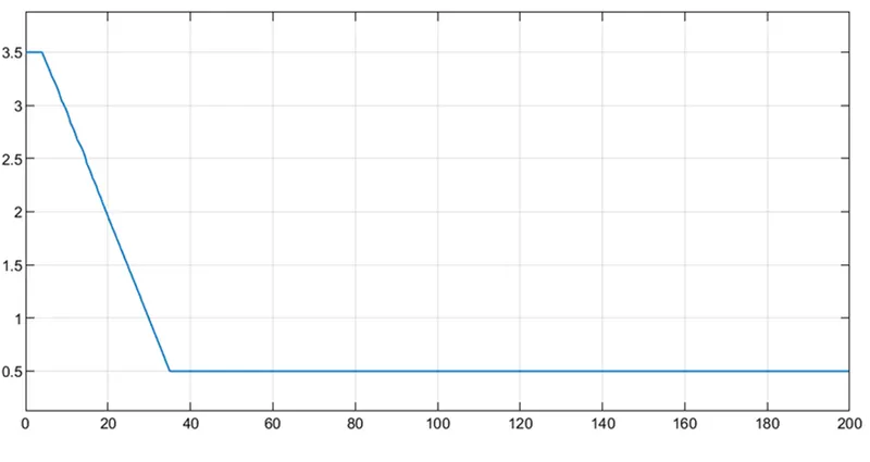
Figure-18
The lookup plot and the CVT Ratio plot is simular.
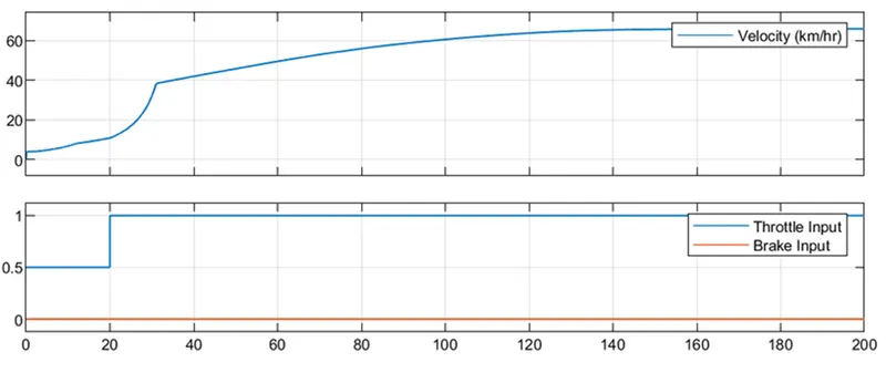
Figure-19
In the above figure the brake is maintained as constant and increase in the throttle which shows increase in the veloity.the flow of fuel is increases from 0.5 20 sec to 1 constant over simulation, thus the power in the engine increases. The torque reaches approximatley 7n-m at 1.8 gear ratio, which defines that gear ratio is directly proportional to the torque .By this gear ratio,the speed & velocity can achieve maximum. the gear ratio is assigned in lookup table and given as input to the simulink which reads every input value and obtain the result according to the input.
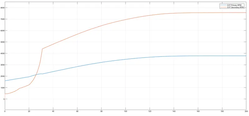
Figure-20
The CVT show variations with respect to primary and secondary RPM based on Gear Ratio.
STUDY-4:-
BAJA ATV MODEL WITH DASHBOARD USING LOOKUP TABLE :-
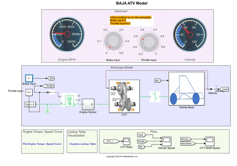
Figure-21
This model is simular to the previous models . the only difference is dashboard along with a lookup table .Here the input can be given using the knobs on the dashboard one is for brake and throttle the simulation changes will show us the impact on vehicle speed.
Here brake input =0 and throttle input =0.5 during the simulation. the lookup table need to be arranged in ascending or descending order to work. we simulationfor an inf period and gave throttle input to get the final results.
RESULTL:-
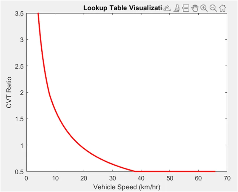
Figure-22
Variation of velocity & shaft speed:-
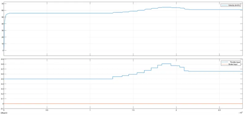
Figure-23
In the above figure , the velocity of the vehicle is maintained as constant for constant throttle value as 0.5 and varying by increasing the value of throttle which increases the velocity of vehicle . brake as maintained value of =0
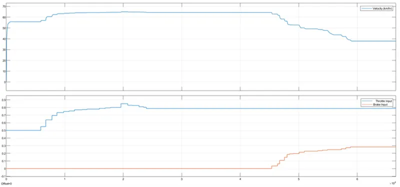
Figure-24
In the above figure , the velocity of the vehicle is maintained as constant for constant throttle value as 0.5 and varying by increasing the value of throttle which increases the velocity of vehicle . brake constant value 0 . and give varying by increaing the brake value and stanley decreaseing the trottle value if will same dicreaseing velocity
CVT Shaft speed:-
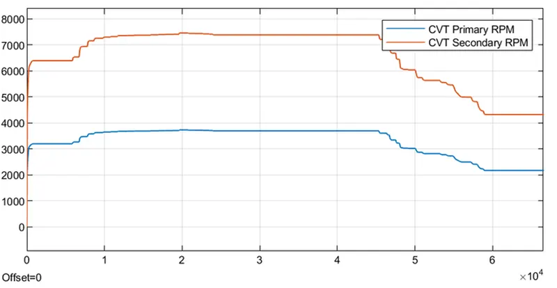
Figure-24
The CVT show variations with respect to primary and secondary RPM based on Gear Ratio.
CONCLUSION:-
We run a system -level simulation for a BAJA ALL-Terrain-vehicle (ATV)model using with CVT model.in the model use to from of engine speed, vehicle speed, and CVT shaft speed helped to determine the vehicle's performance.