1. Wiper control system
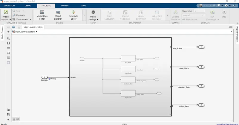
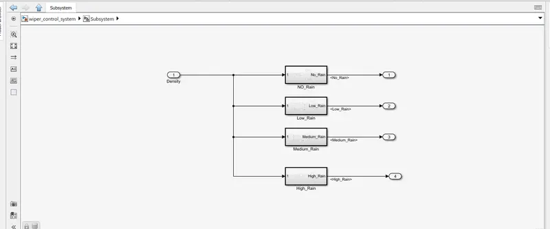
Develop Simulink/state flow model for wiper control system based on the given conditions.
Description of Challenge:
- If the density of the rain is low, then wiper rotates with low speed & the output signal should be 100rpm
- If the density of the rain is medium, then wiper rotates with medium speed & the output signal should be 200rpm
- If the density of the rain is high, then wiper rotates with high speed & the output signal should be 500rpm
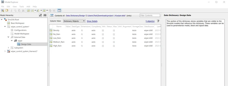
Note: Rain density input comes from the external sensor, for the simulation purpose constant block with knob can be taken.
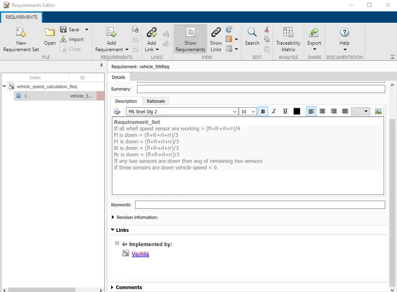
Requirement tagging:
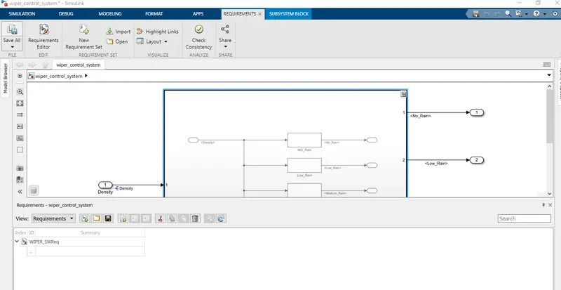
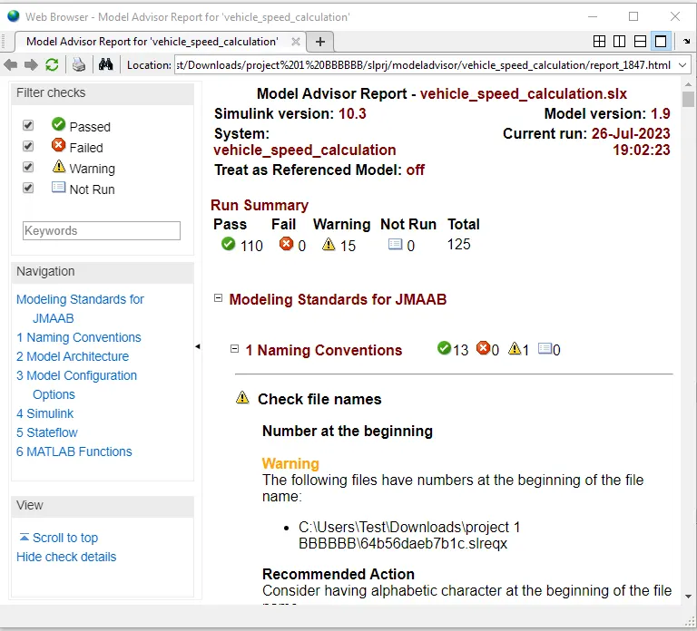
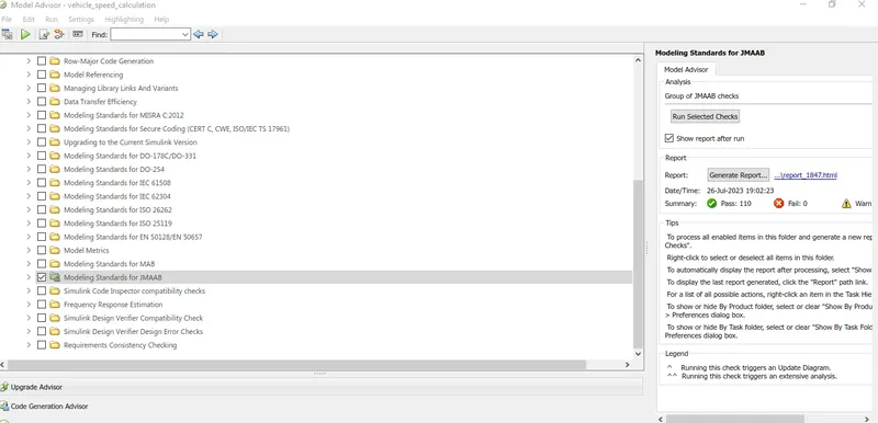
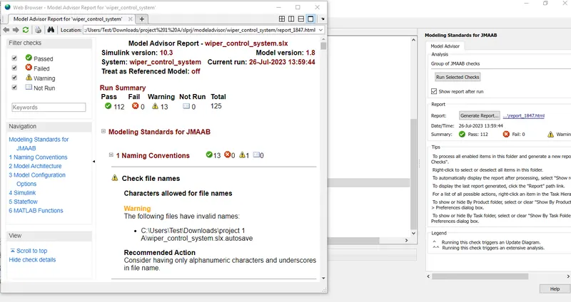
MA Report:
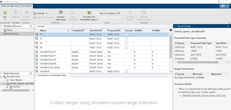
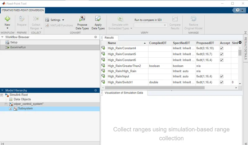
Fixed Point Tool:
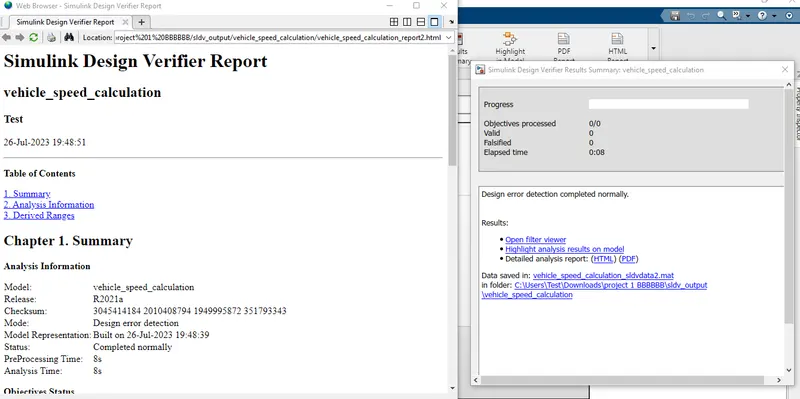
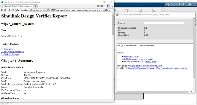
SLDV Design Error Detection Report:
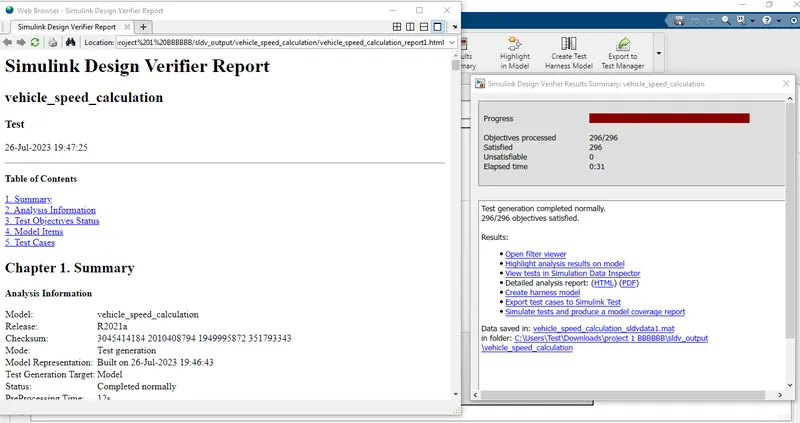
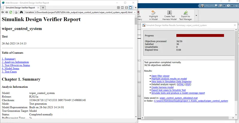
SLDV Test Generation Report:
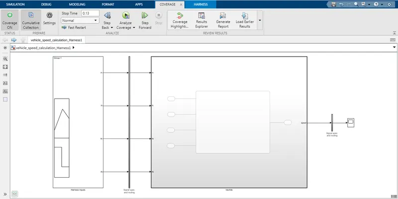
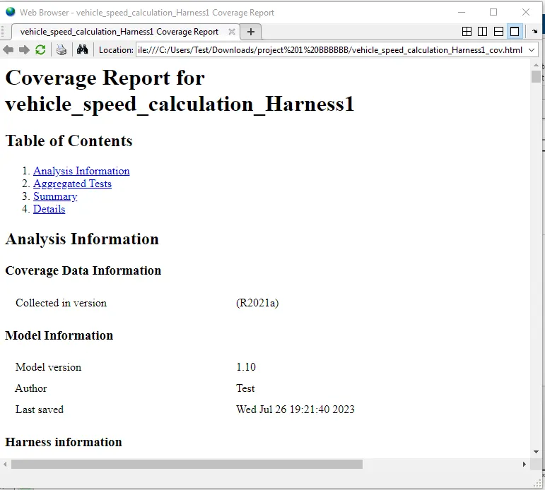
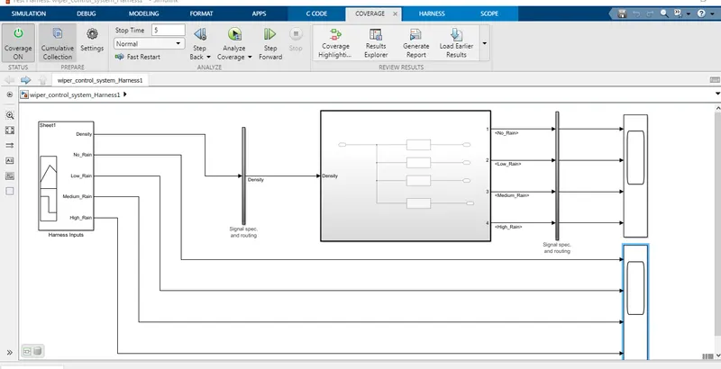
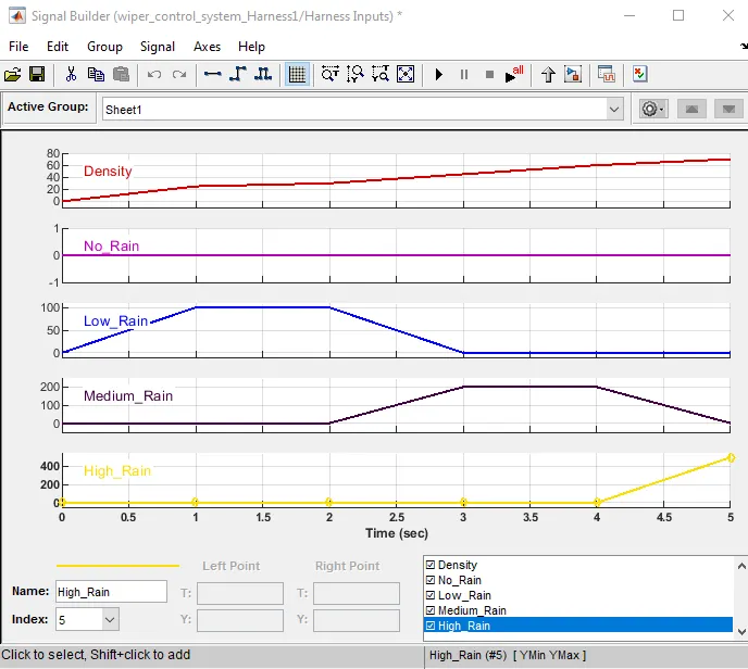
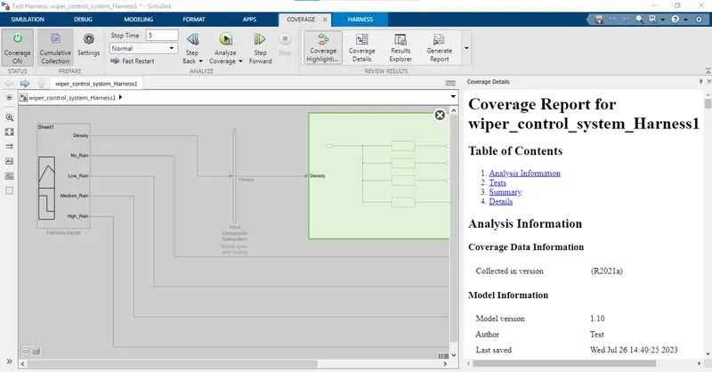
Functional Test Caes MIL,SIL Harness and Coverage Report:
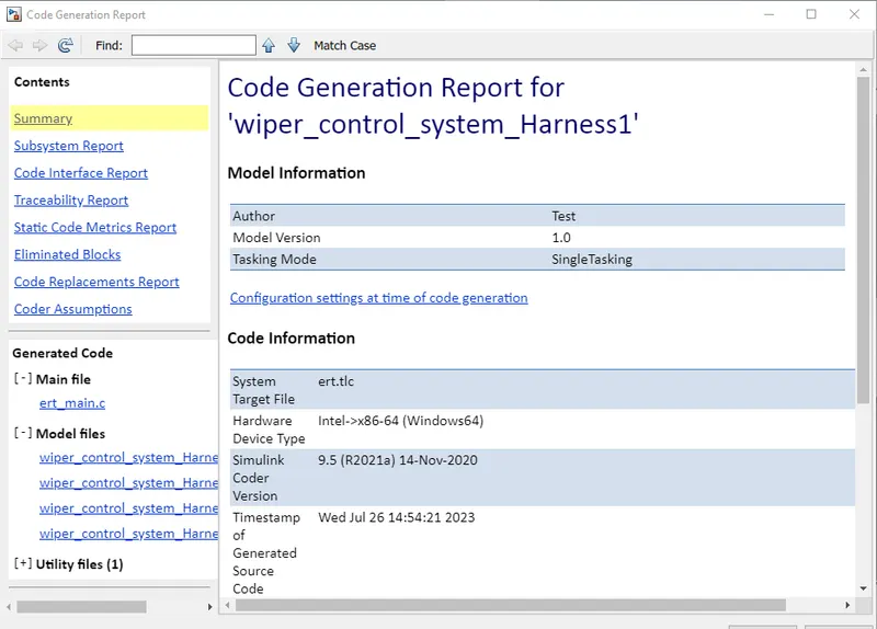
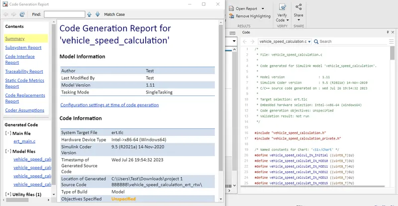
Auto Code Generation Report:
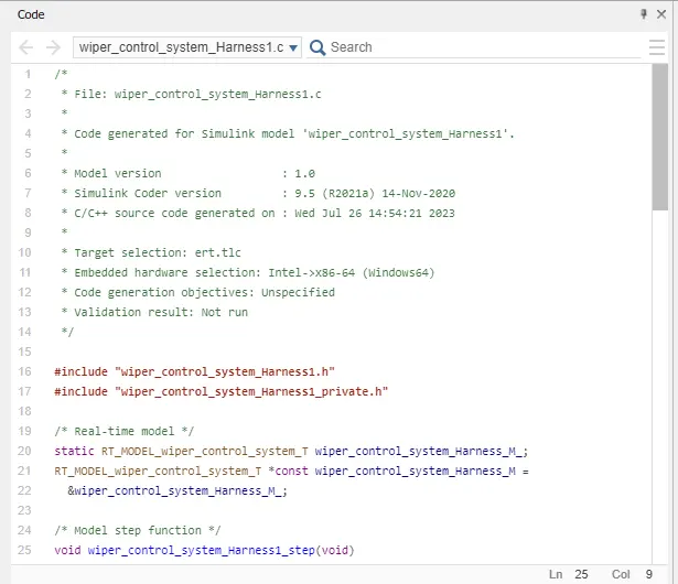
* File: wiper_control_system_Harness1.c
* Code generated for Simulink model 'wiper_control_system_Harness1'.
* Simulink Coder version : 9.5 (R2021a) 14-Nov-2020
* C/C++ source code generated on : Wed Jul 26 14:54:21 2023
* Target selection: ert.tlc
* Embedded hardware selection: Intel->x86-64 (Windows64)
* Code generation objectives: Unspecified
* Validation result: Not run
#include "wiper_control_system_Harness1.h"
#include "wiper_control_system_Harness1_private.h"
static RT_MODEL_wiper_control_system_T wiper_control_system_Harness_M_;
RT_MODEL_wiper_control_system_T *const wiper_control_system_Harness_M =
&wiper_control_system_Harness_M_;
/* Model step function */
void wiper_control_system_Harness1_step(void)
/* Update absolute time for base rate */
/* The "clockTick0" counts the number of times the code of this task has
* been executed. The absolute time is the multiplication of "clockTick0"
* and "Timing.stepSize0". Size of "clockTick0" ensures timer will not
* overflow during the application lifespan selected.
wiper_control_system_Harness_M->Timing.t[0] =
((time_T)(++wiper_control_system_Harness_M->Timing.clockTick0)) *
wiper_control_system_Harness_M->Timing.stepSize0;
/* Update absolute timer for sample time: [1.0s, 0.0s] */
/* The "clockTick1" counts the number of times the code of this task has
* been executed. The resolution of this integer timer is 1.0, which is the step size
* of the task. Size of "clockTick1" ensures timer will not overflow during the
* application lifespan selected.
wiper_control_system_Harness_M->Timing.clockTick1++;
/* Model initialize function */
void wiper_control_system_Harness1_initialize(void)
/* Setup solver object */
rtsiSetSimTimeStepPtr(&wiper_control_system_Harness_M->solverInfo,
&wiper_control_system_Harness_M->Timing.simTimeStep);
rtsiSetTPtr(&wiper_control_system_Harness_M->solverInfo, &rtmGetTPtr
(wiper_control_system_Harness_M));
rtsiSetStepSizePtr(&wiper_control_system_Harness_M->solverInfo,
&wiper_control_system_Harness_M->Timing.stepSize0);
rtsiSetErrorStatusPtr(&wiper_control_system_Harness_M->solverInfo,
(&rtmGetErrorStatus(wiper_control_system_Harness_M)));
rtsiSetRTModelPtr(&wiper_control_system_Harness_M->solverInfo,
wiper_control_system_Harness_M);
rtsiSetSimTimeStep(&wiper_control_system_Harness_M->solverInfo,
rtsiSetSolverName(&wiper_control_system_Harness_M->solverInfo,
rtmSetTPtr(wiper_control_system_Harness_M,
&wiper_control_system_Harness_M->Timing.tArray[0]);
wiper_control_system_Harness_M->Timing.stepSize0 = 1.0;
/* Model terminate function */
void wiper_control_system_Harness1_terminate(void)
/* (no terminate code required) */
* File trailer for generated code.
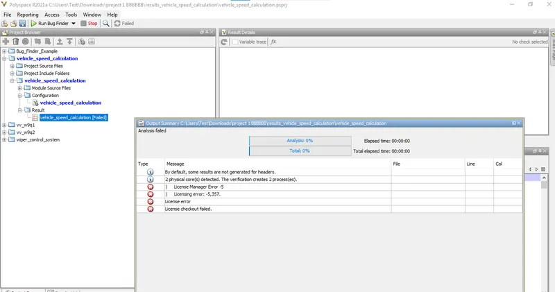
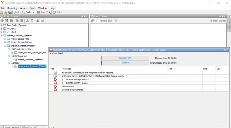
Poly Space Analysis Report:
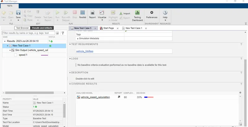
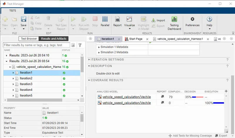
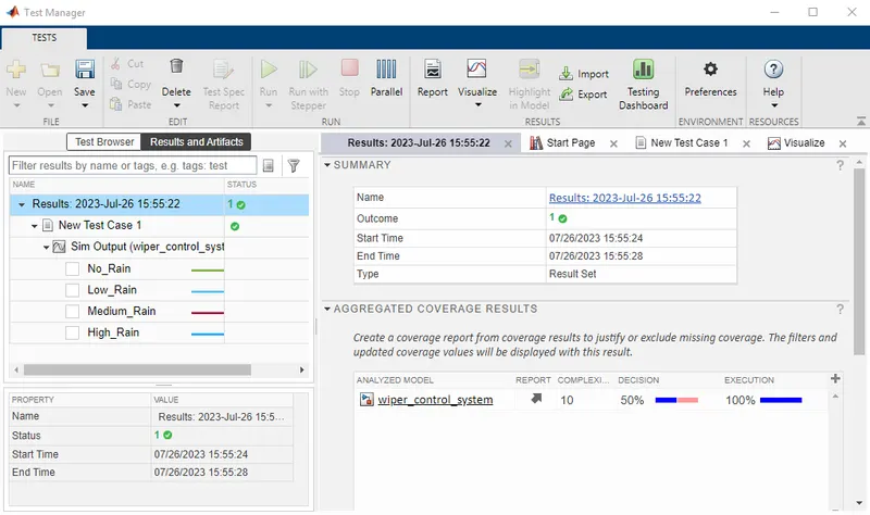
Test Manager Report:
-Base Line Testing
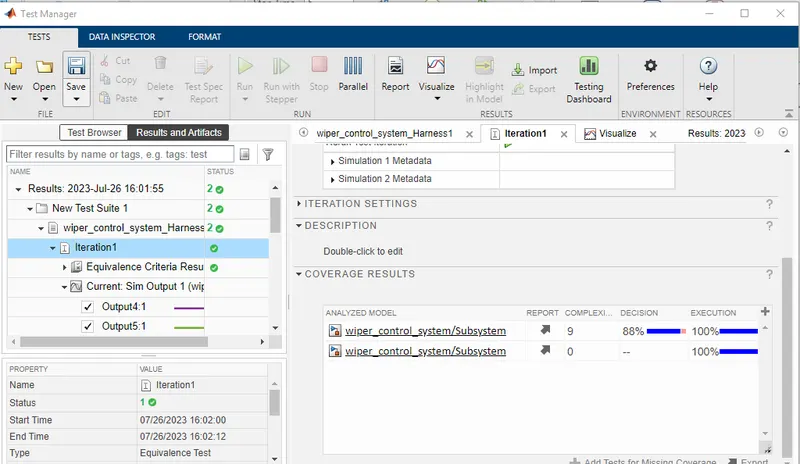
- Back to Back Testing:
2.Vehicle speed calculation for ABS using Wheel Speed sensor
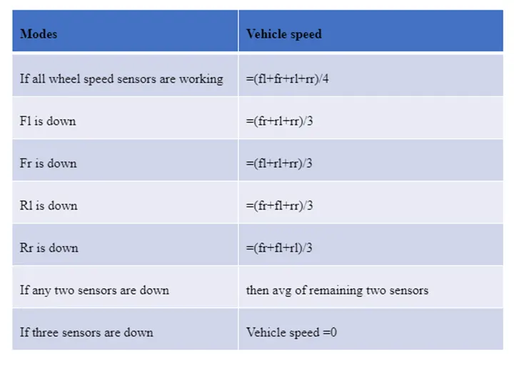
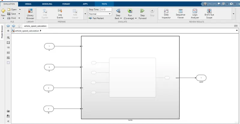
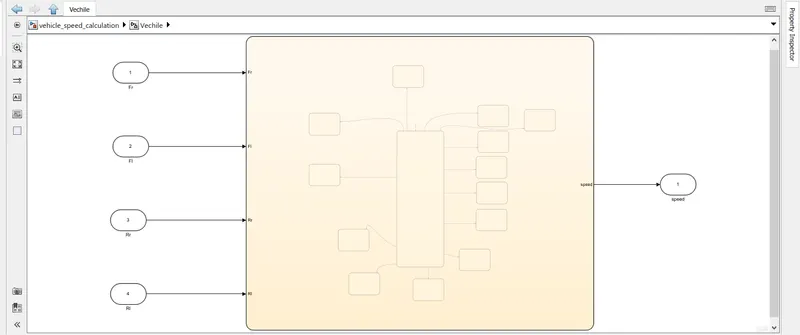
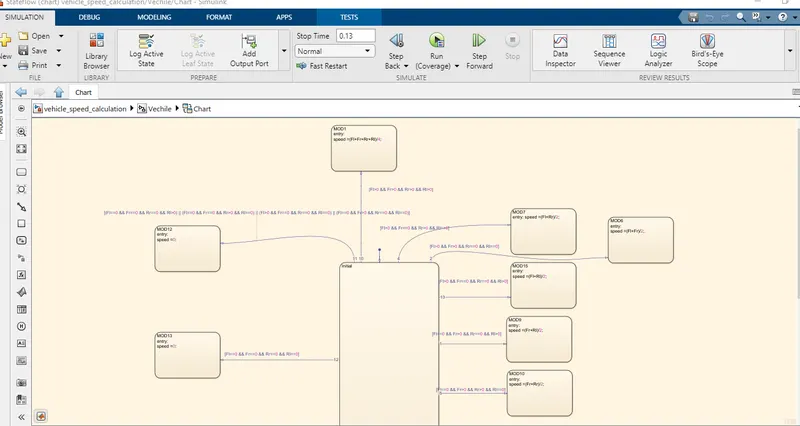
Develop Simulink/state flow model for the vehicle speed calculation unit inside the ABS system for the below conditions.
Description of Challenge:
fl, fr, rl and rr are the wheel speeds of front left, front right, rear left and rear right respectively.