Project 1 - Wiper control system and Vehicle speed calculation for ABS using Wheel Speed sensor
1)
- Wiper control system
Develop Simulink/state flow model for wiper control system based on the given conditions.
Description of Challenge:
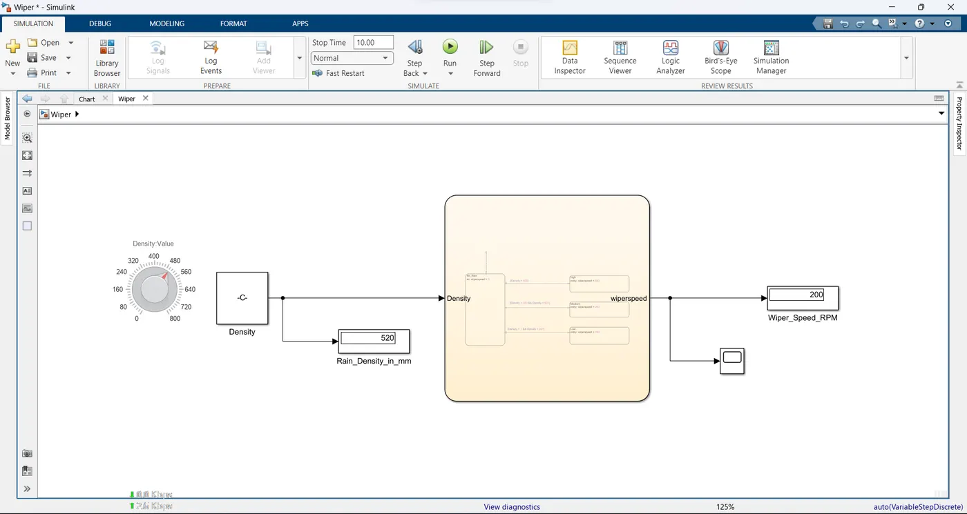
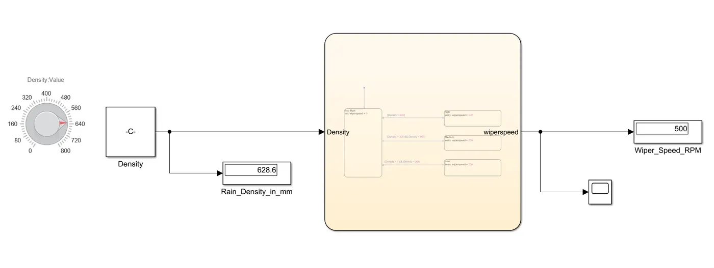
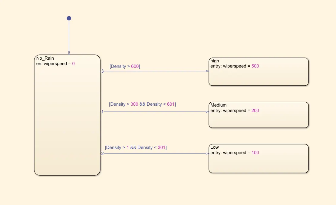
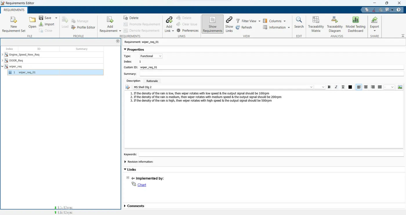
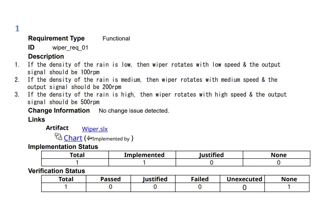
- If the density of the rain is low, then wiper rotates with low speed & the output signal should be 100rpm
- If the density of the rain is medium, then wiper rotates with medium speed & the output signal should be 200rpm
- If the density of the rain is high, then wiper rotates with high speed & the output signal should be 500rpm
Solution:
Low density = 0 -300 mm
medium density = 301-600 mm
High density = above 601 mm
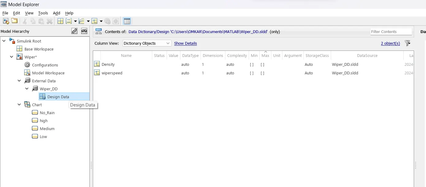
SLDD:
Requirement Tagging and link:
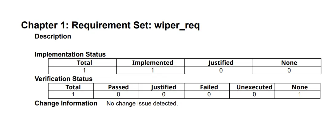
Requirement tagging Report:

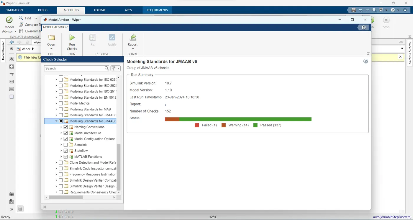
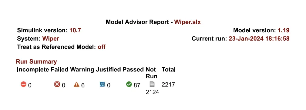
JMAAB Report:
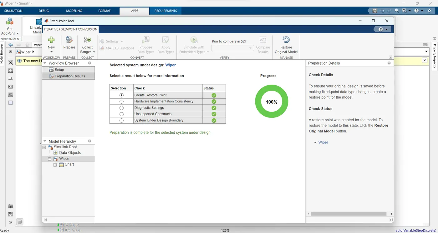
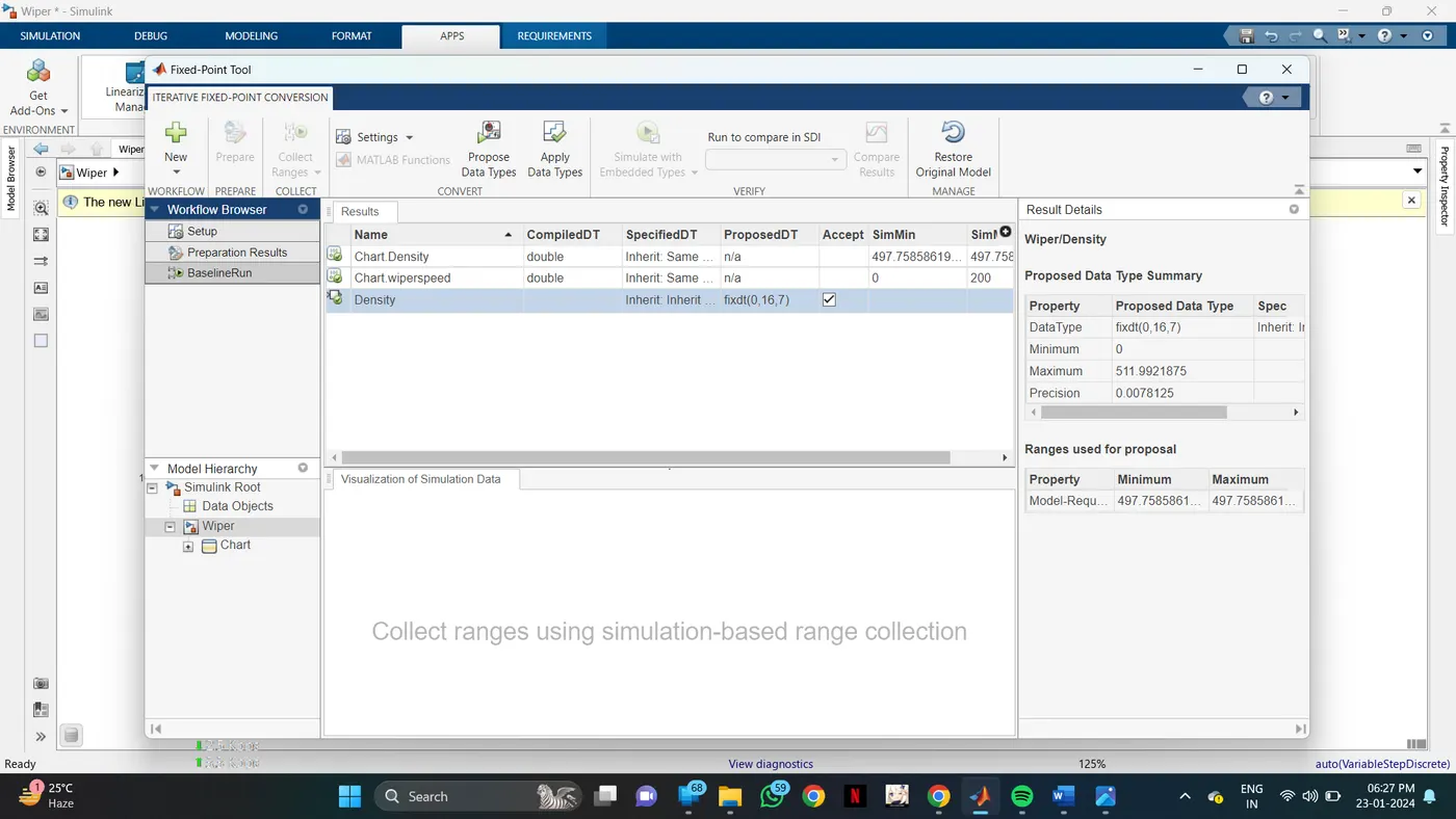
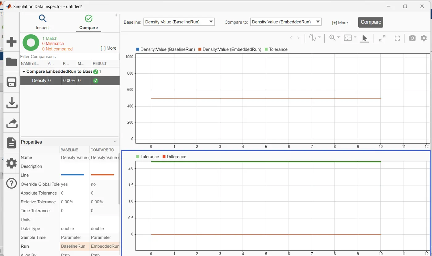
Fixed point tool:
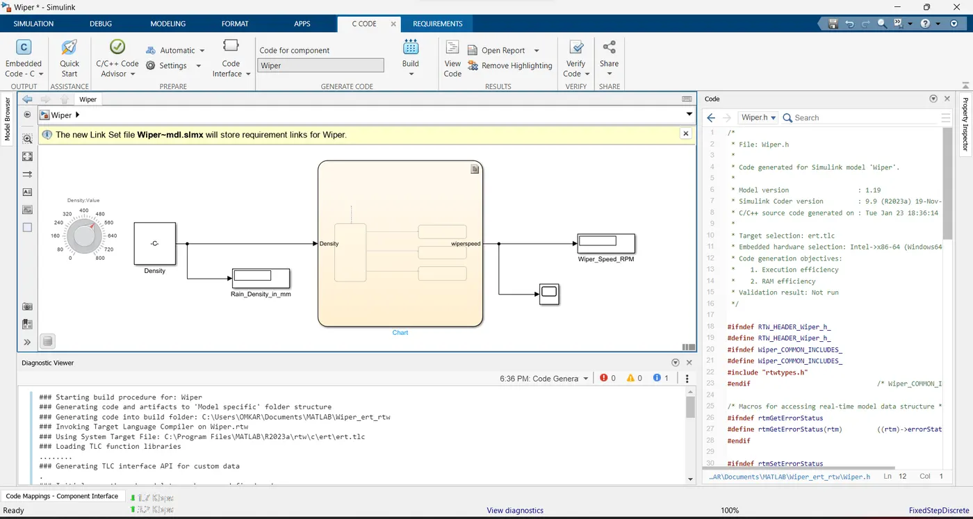
Code generation Report:

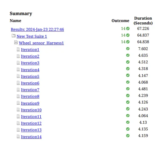
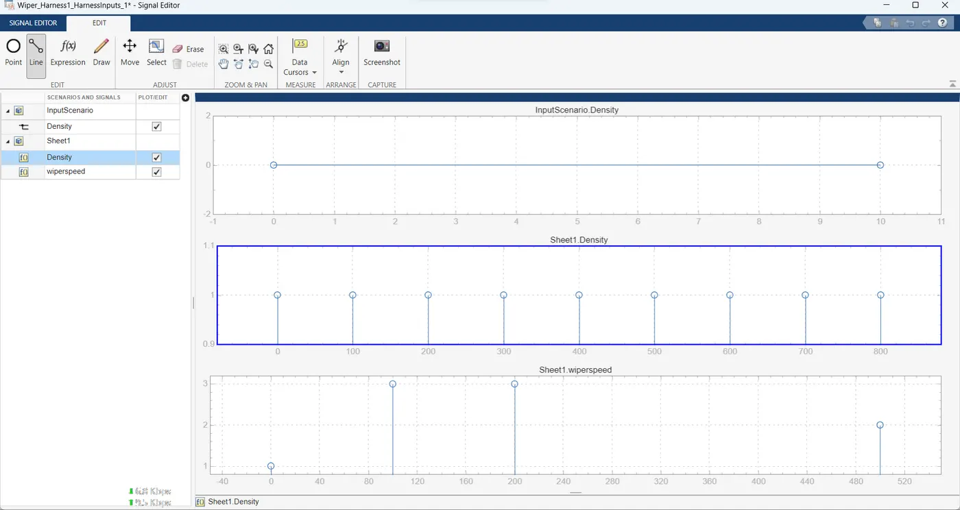
MIL Harness:
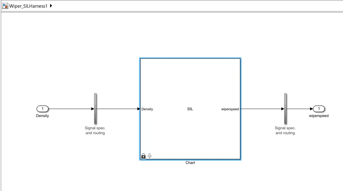
SIL :
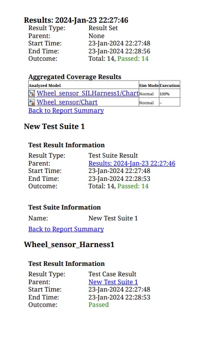
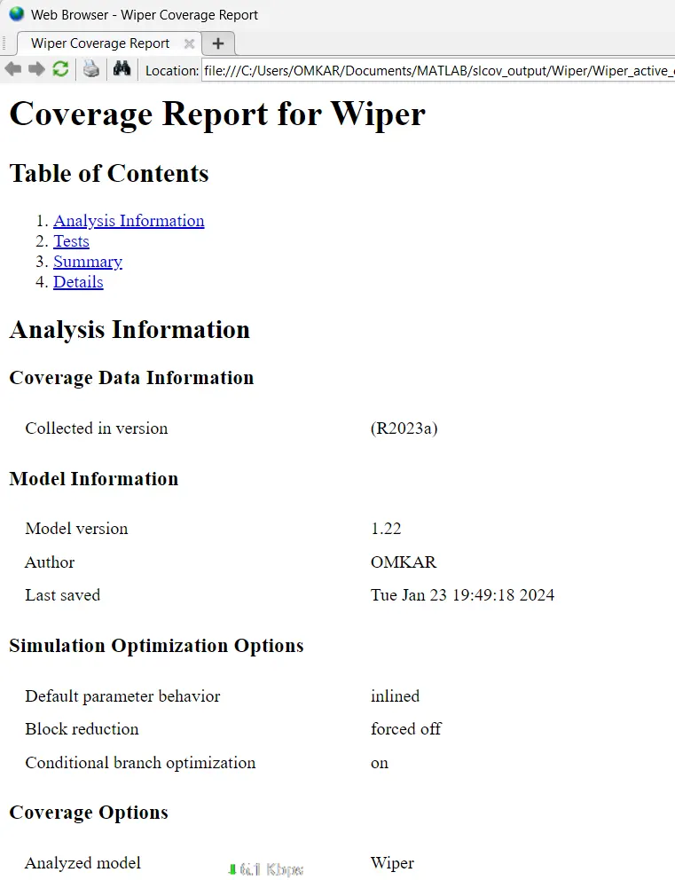
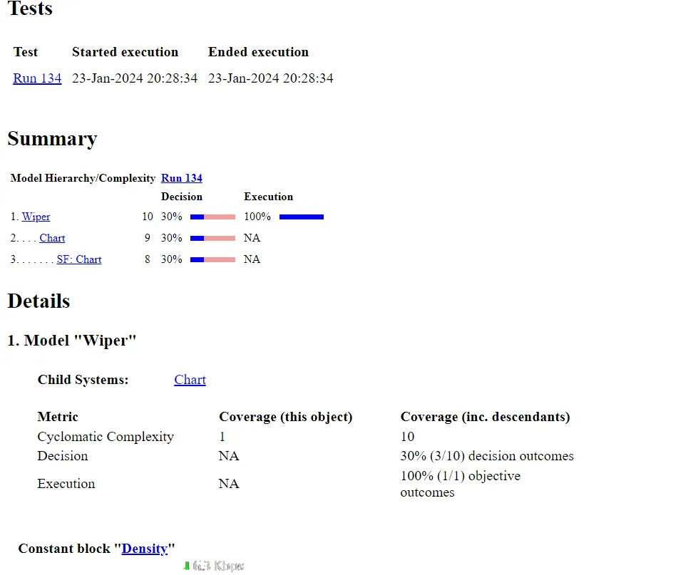
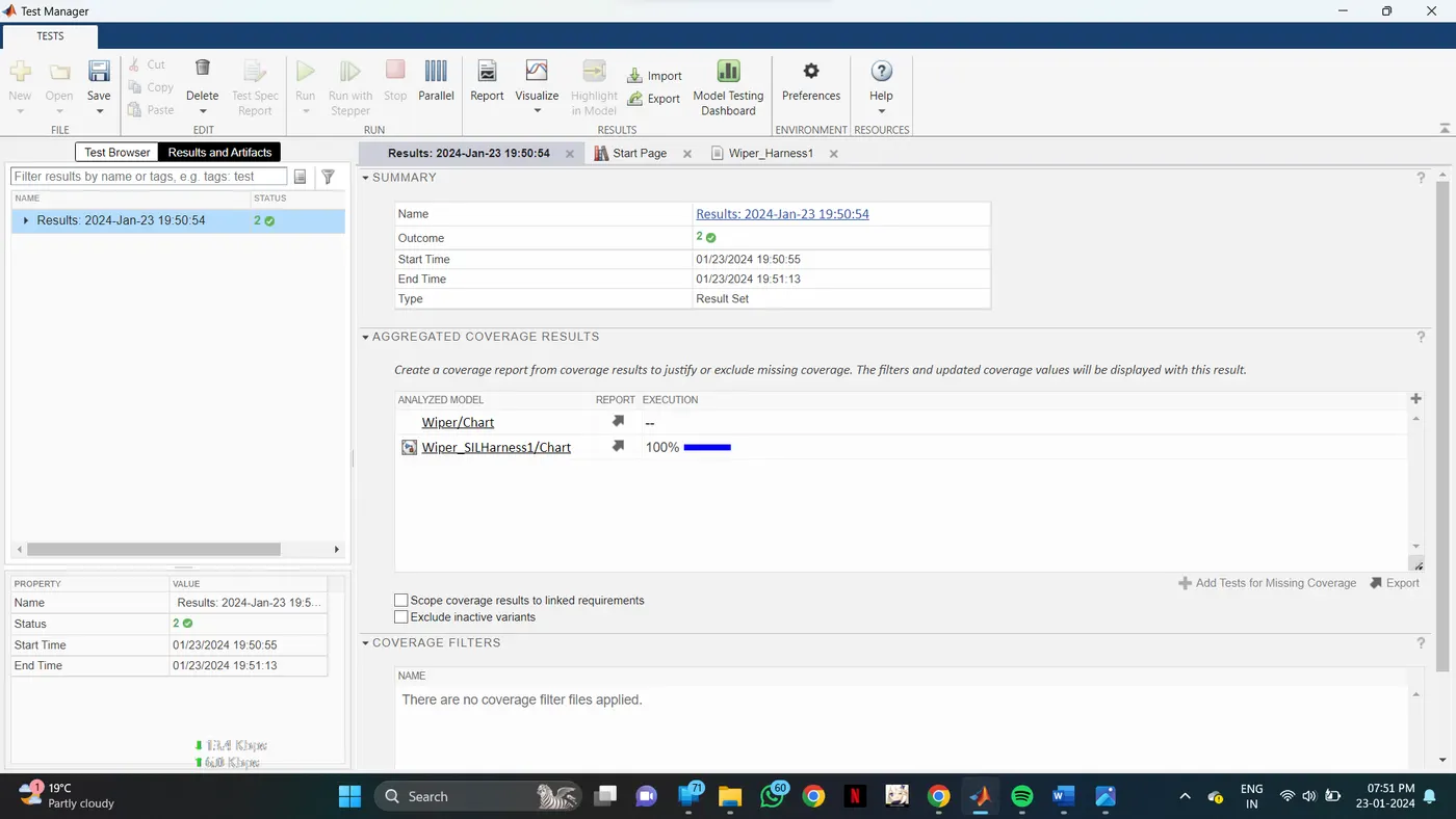
Coverage Report:
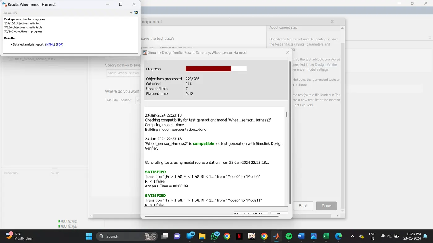
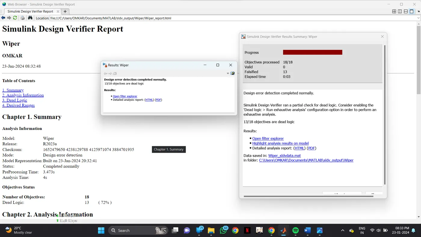
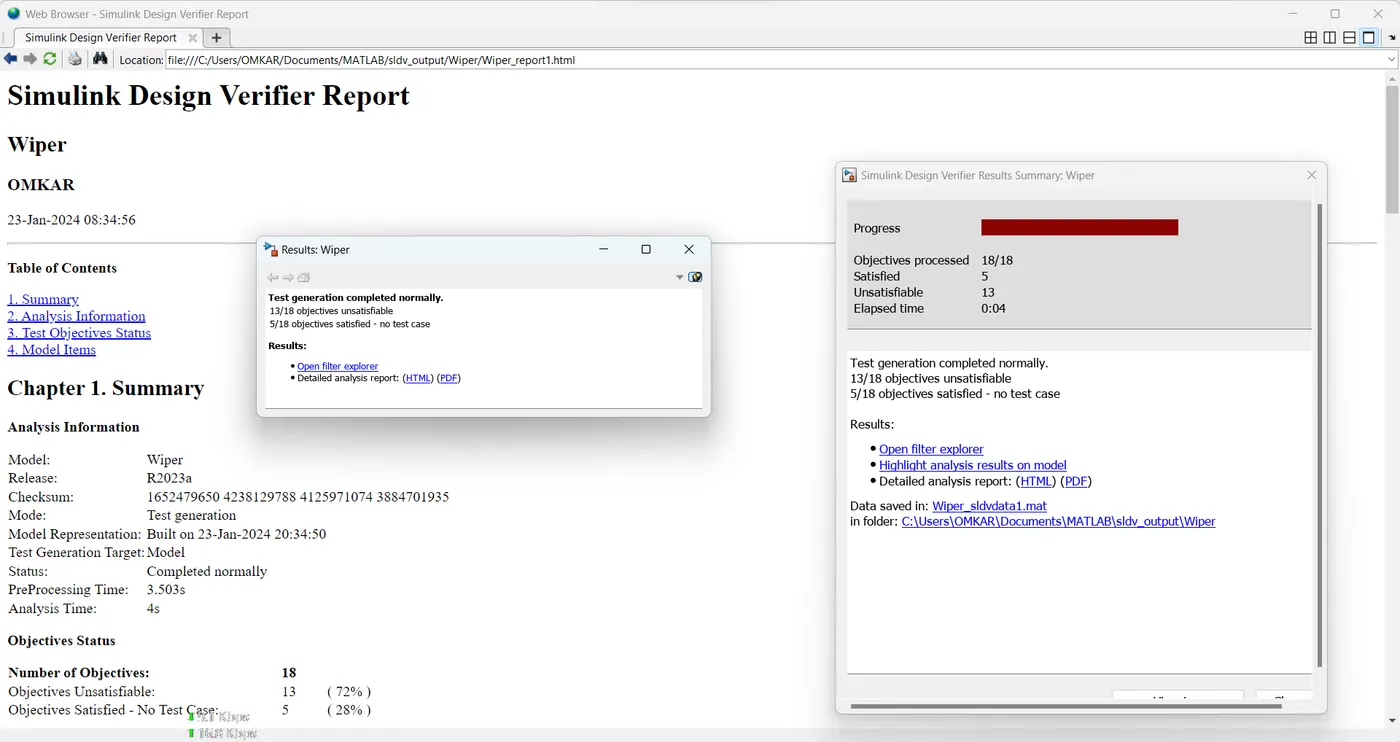
SLDV Report:
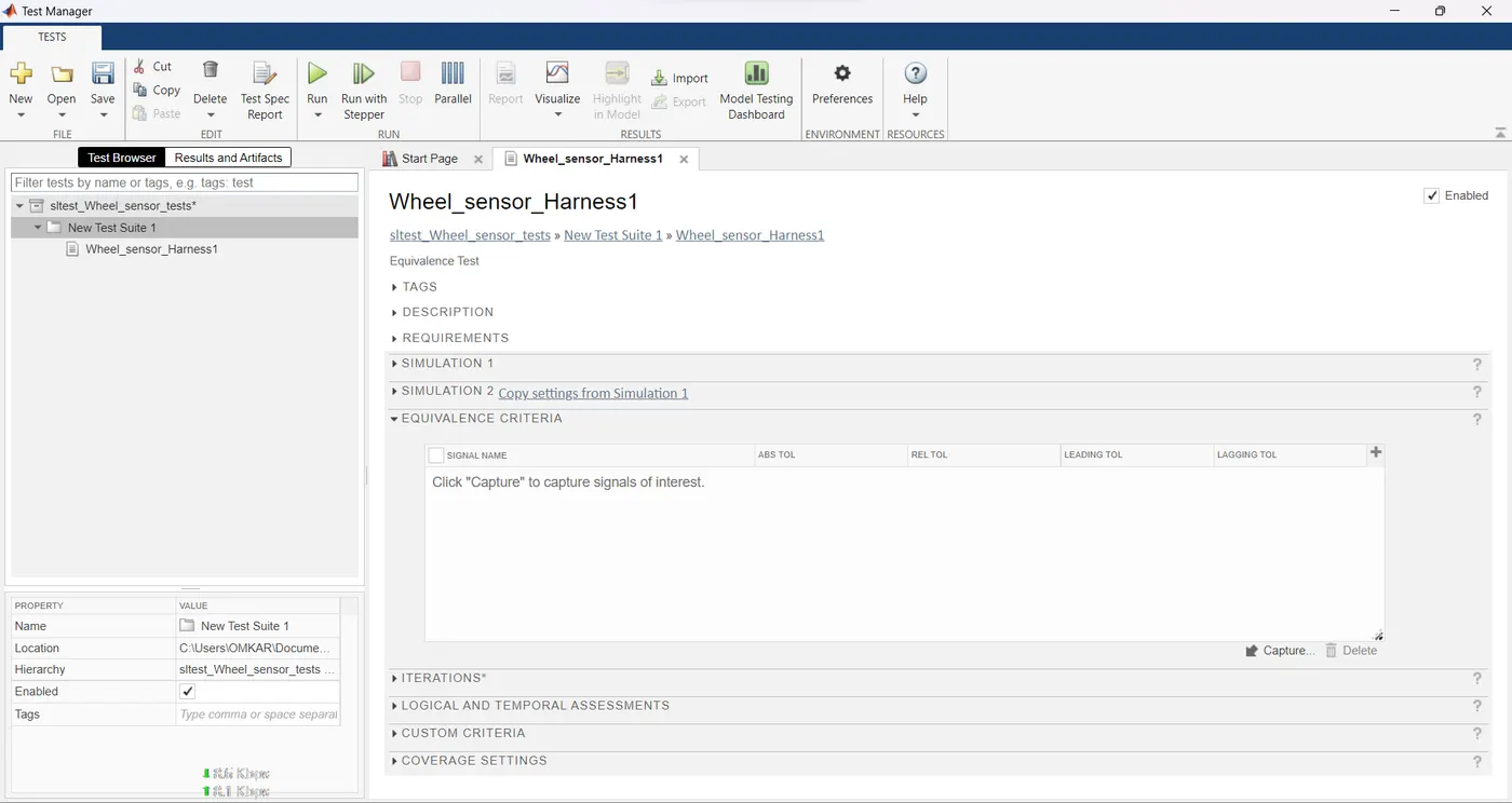
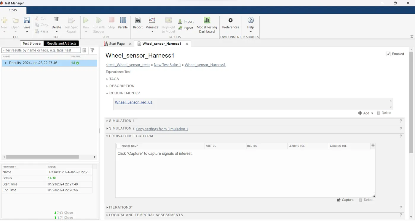
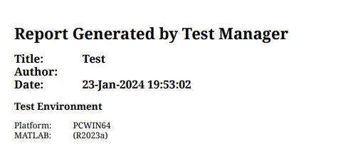
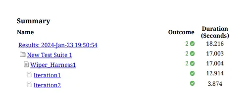
Back To Back Test:
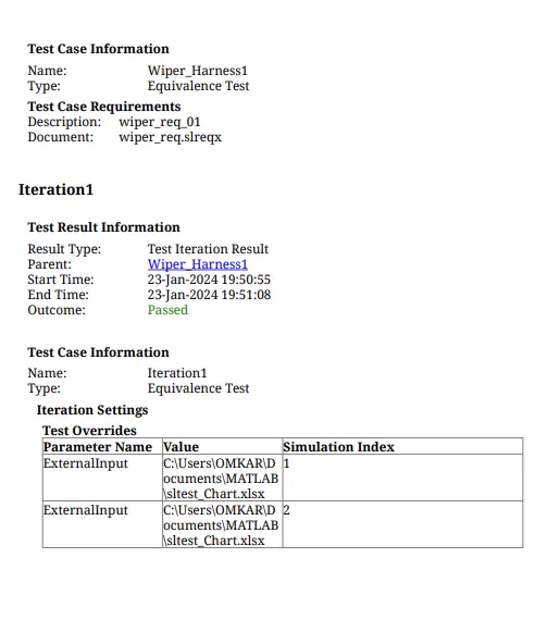
2)
Vehicle speed calculation for ABS using Wheel Speed sensor
Develop Simulink/state flow model for the vehicle speed calculation unit inside the ABS system for the below conditions.
Description of Challenge:
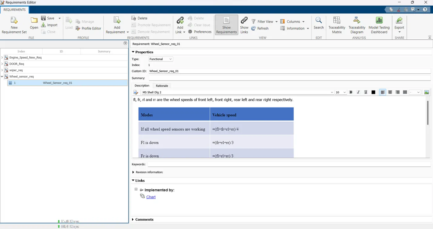
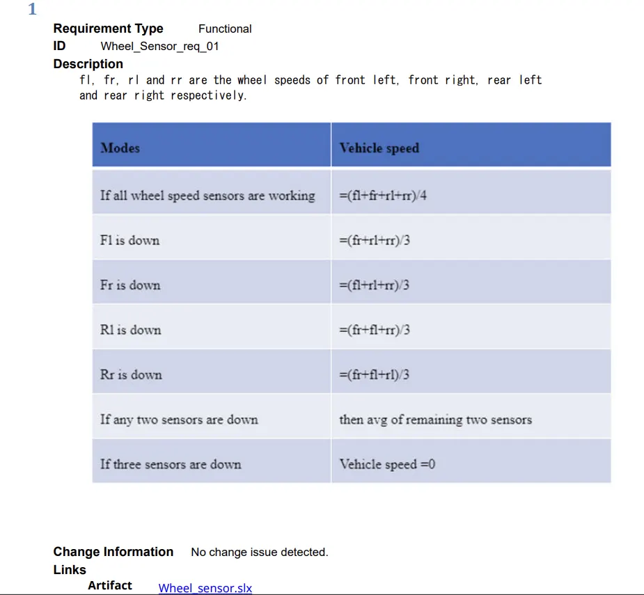
fl, fr, rl and rr are the wheel speeds of front left, front right, rear left and rear right respectively.
Note: Based on the conditions, requirements can be framed up.
Solution:
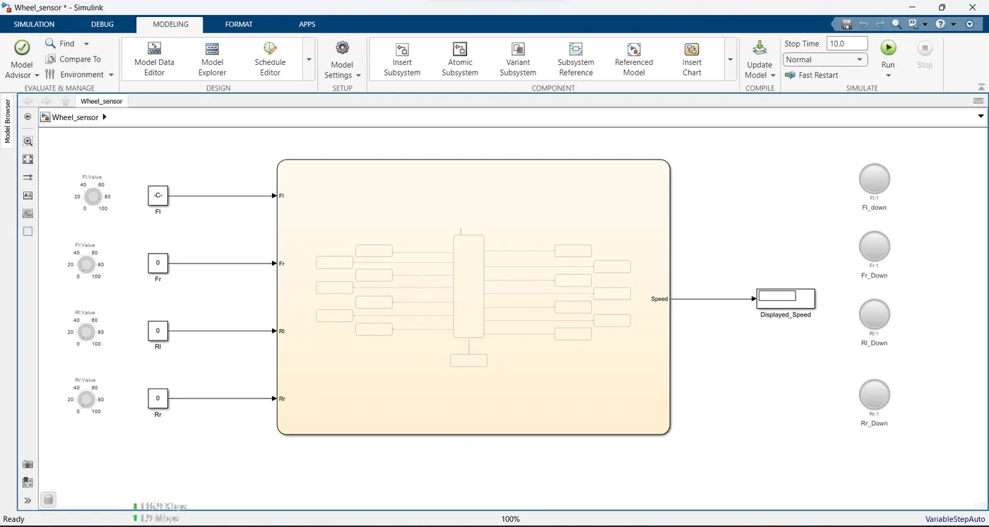
- Four knobs are connected to chart to verify sensor values.
- All knobs are connected to LED to indicate which sensor is down.
- If LED glows it means the connected sensor gives 0 output when the vehicle is running and that sensor is not working.
- If LED is off then sensor is working.
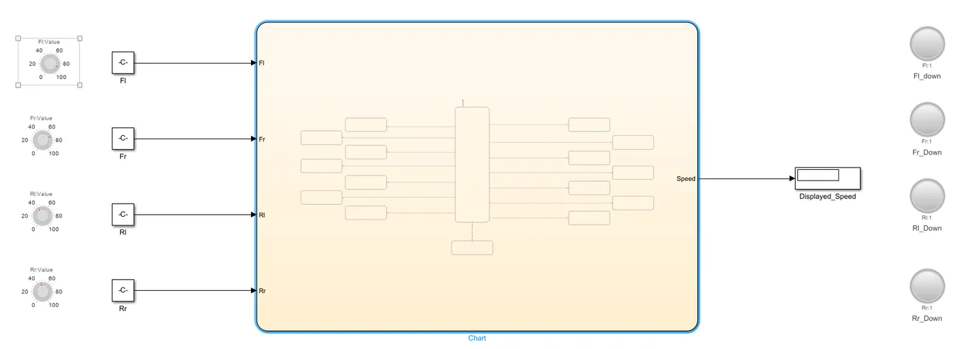
In above case All sensors Are working.
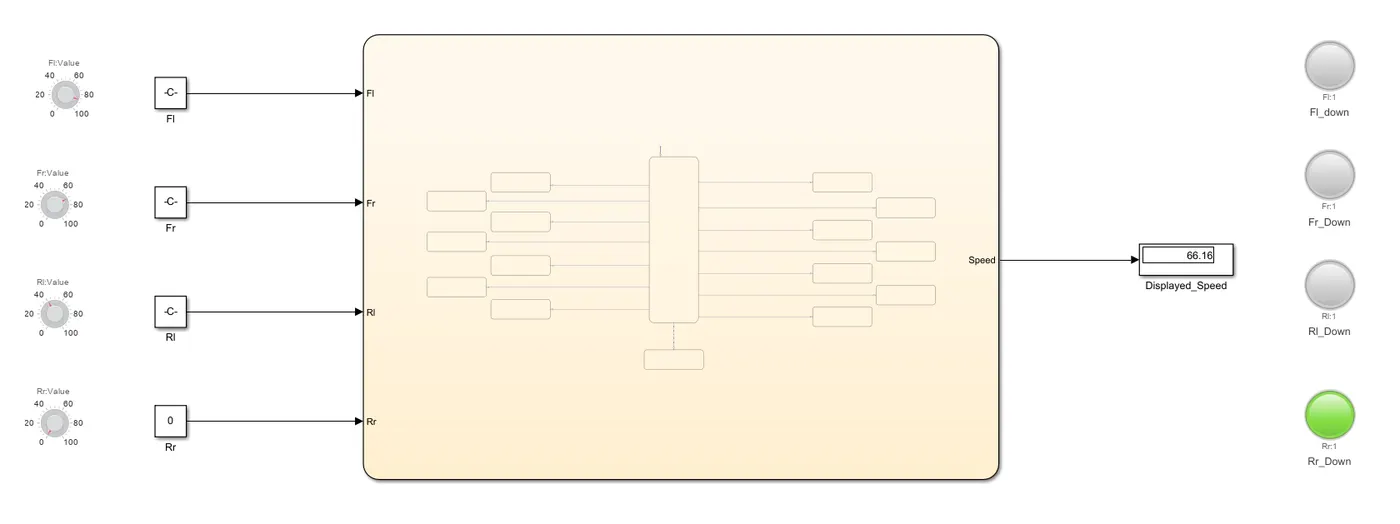
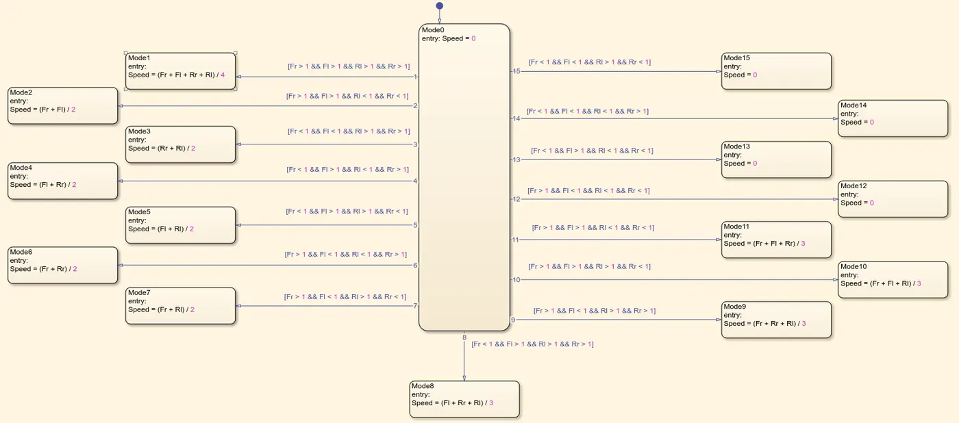
In above case one sensor is down speed shows average of remaining three
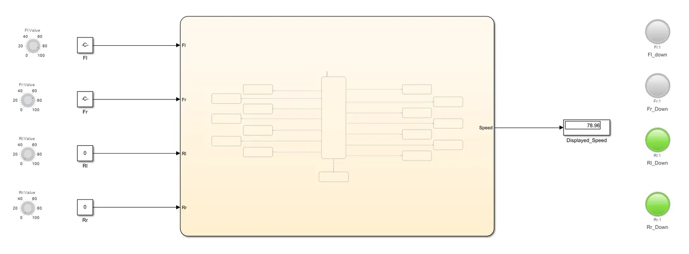
In above case two sensors are down and speed shows average of remaining two
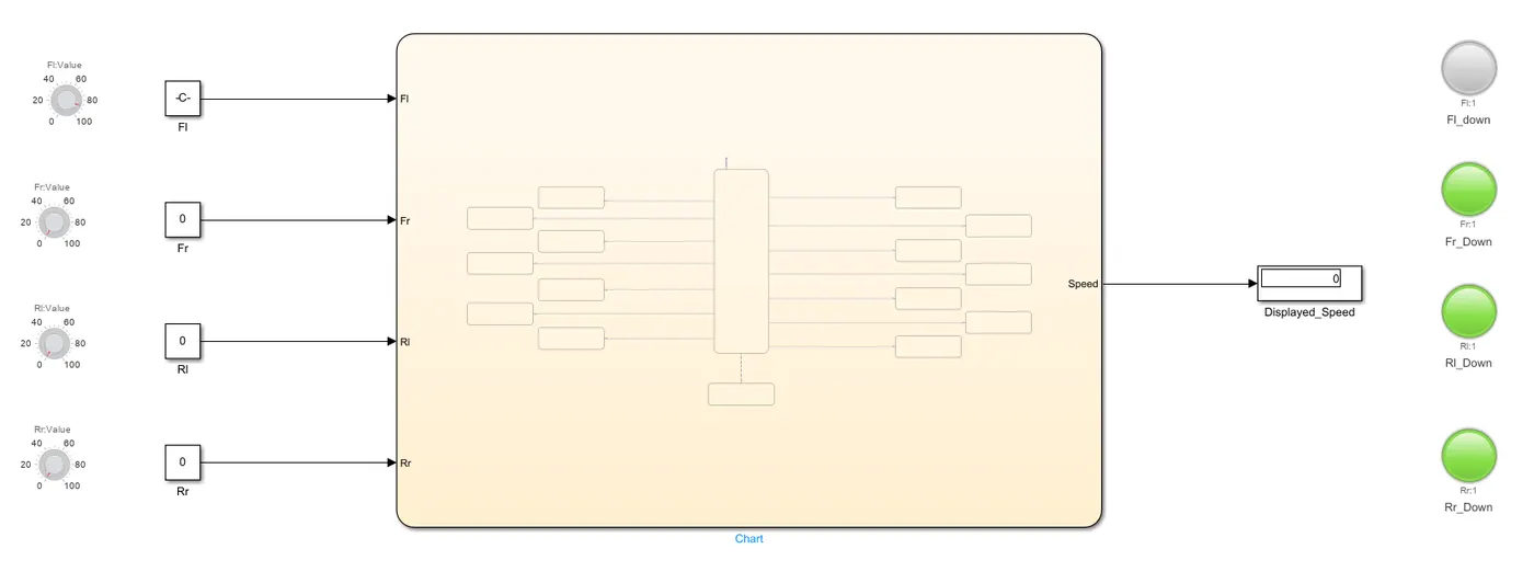
In above case 3 sensors are down and speed shows 0
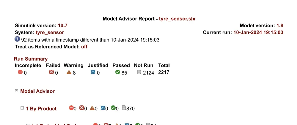
JMAAB Report :
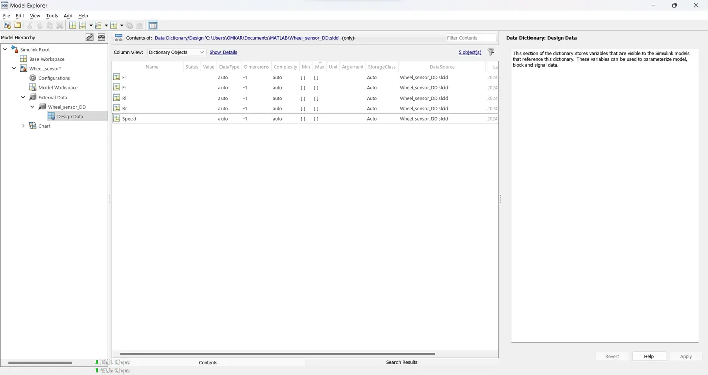
SLDD:
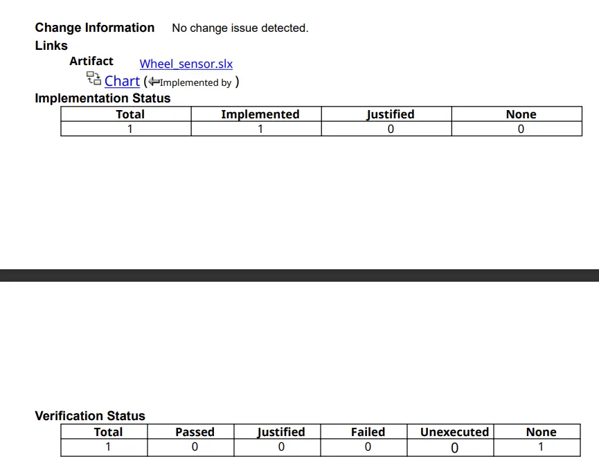
Requirement Tagging:

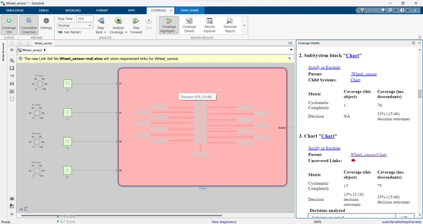
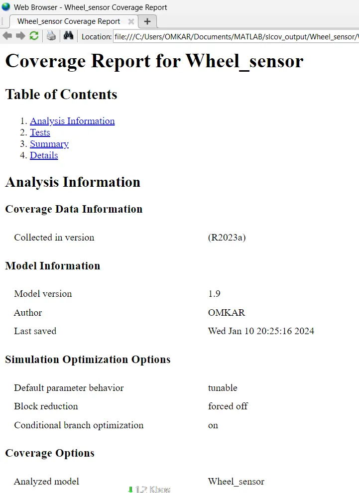
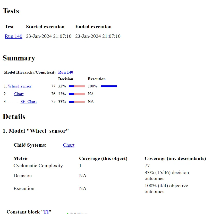
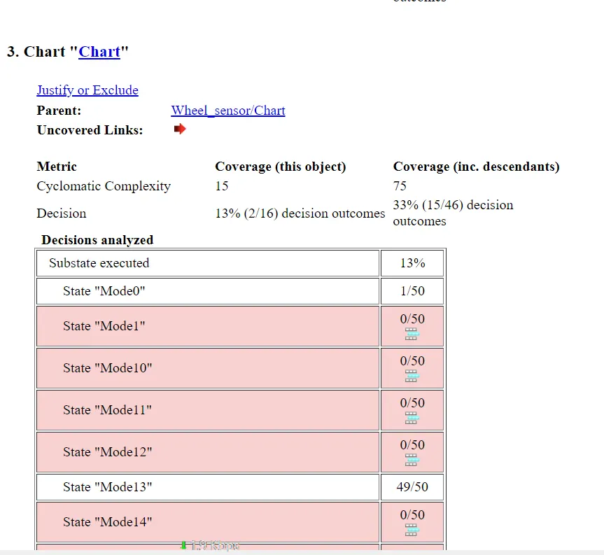
Coverage Report:
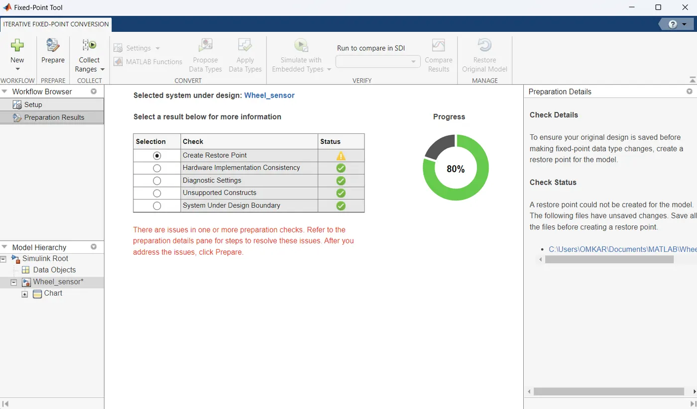
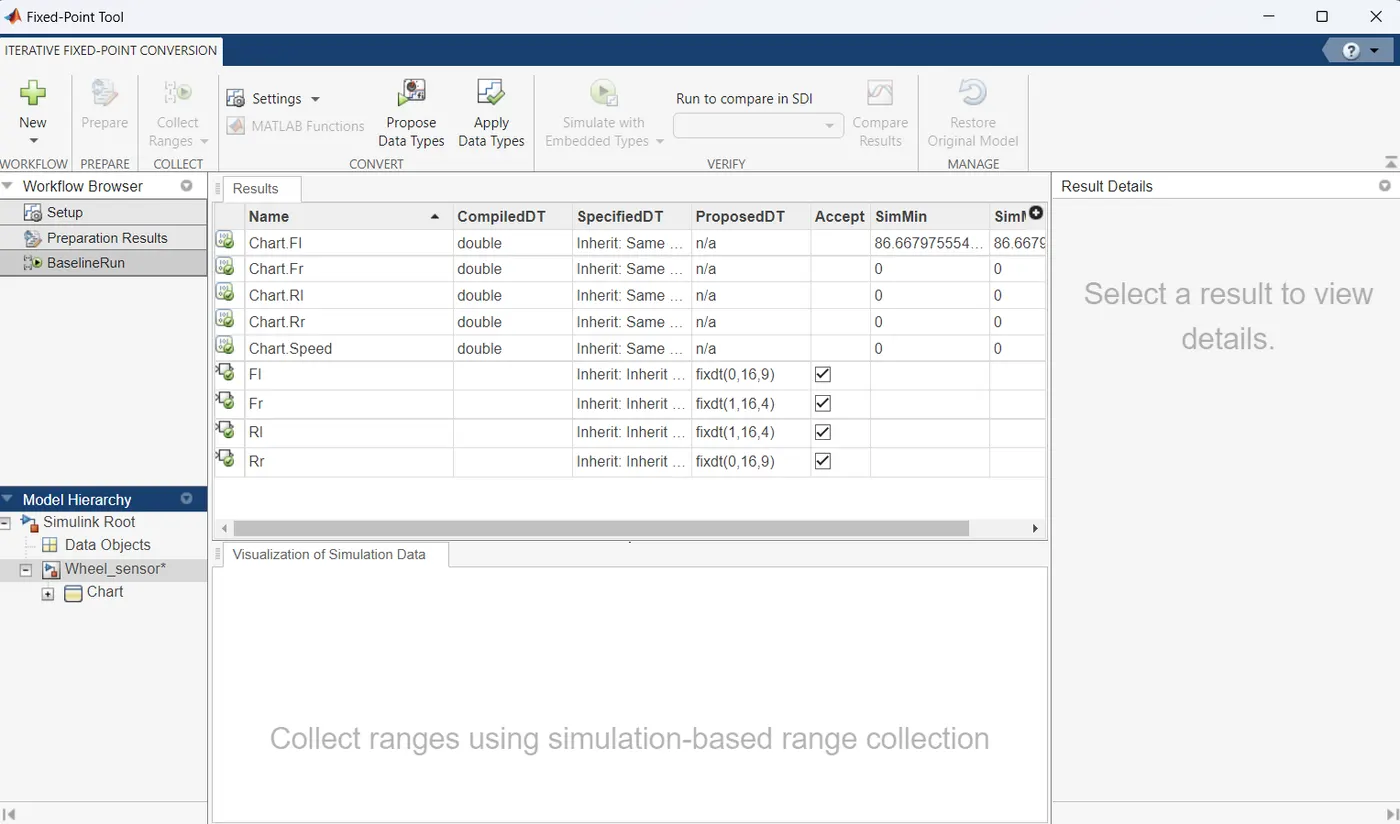
Fixed Point Tool:
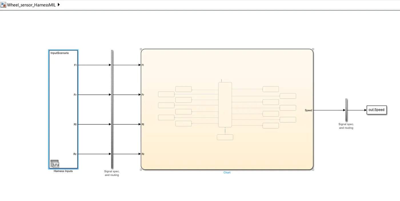
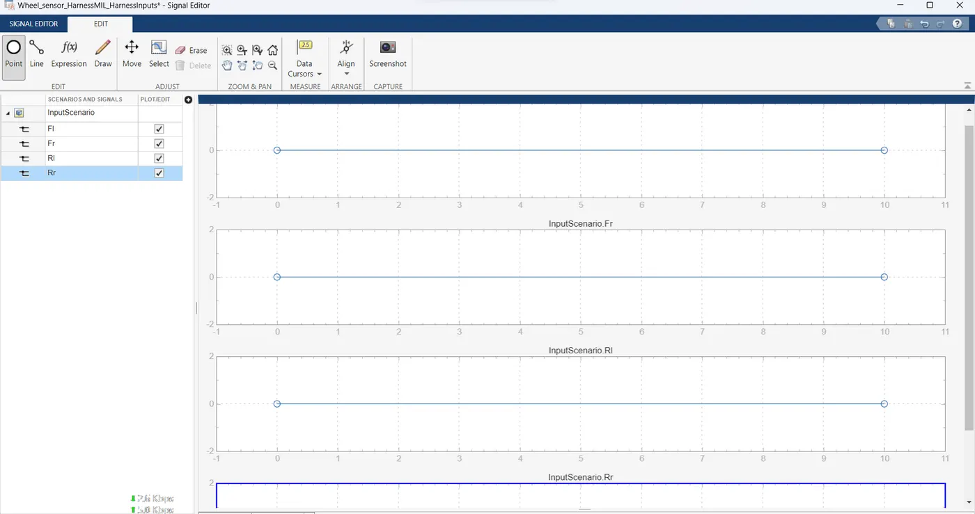
MIL:
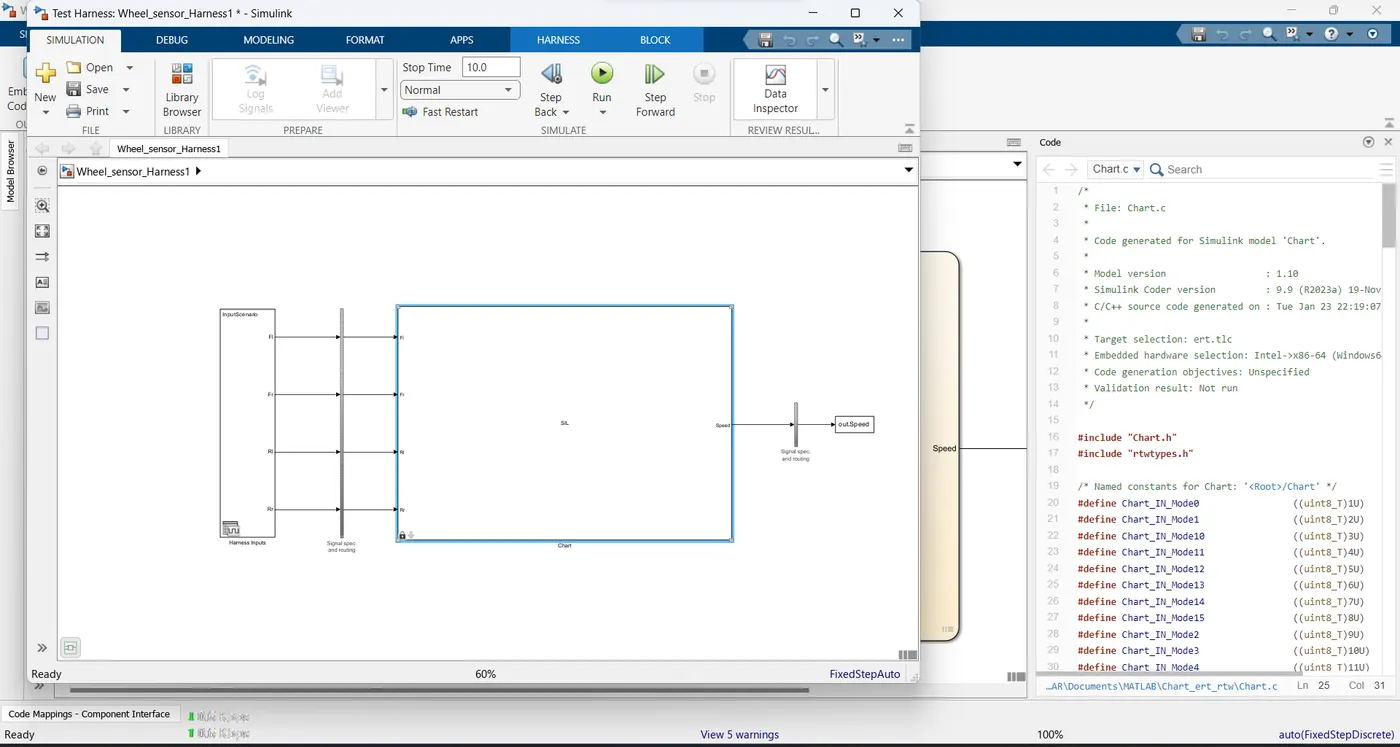
SIL:
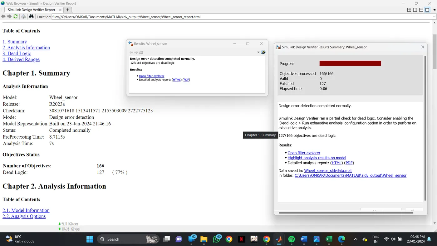
SLDV Report:
Back To Back testing: