Project 1- Traffic Jam Assistant Feature
AIM:
- To develop one specific requirement of Traffic Jam Assistant algorithm which would predominantly feature in the Instrument Panel Cluster (IPC) algorithm must be developed in MATLAB Simulink as per MBD (MAAB) guidelines.
- To create a Simulink Data Dictionary of the model and map it to the current model
- To Generate Model Advisor Report for the current model as per MAAB Guidelines
- To generate code for the Simulink model using Embedded Coder.
Simulink Model
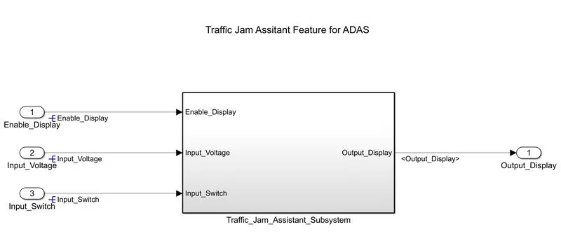
Figure 1: Top Level Model of Traffic Jam Assistant Feature
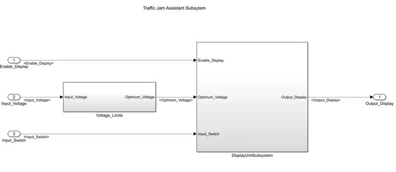
Figure 2: Traffic Jam Assistant Subsystem
Step1: Requirement Analysis
- Based on the Requirements provided, the Inputs, Outputs and control logic has been decided.
- Requirement Analysis is a very useful method or tool as it simplifies the problem based on what requirements are needed to implement the algorithm.
- All the requirements are defined by building the Model Based on the requirements it is the fastest way to achieve a solution to the problem.
- Requirements traceability connects models, tests, and code with requirement definitions to help manage change and reduce time in the design life cycle.
In Traffic Jam Assistant Algorithm there are 2 main requirements
- Voltage Limit
- Display Unit Subsystem
Requirement No 1: Voltage Limit
Inputs Signal: Input Voltage
Output Signals: Optimum_Voltage
Logic:
- Input Signal “Input_Voltage” is compared against voltage values VOLTAGE_MINIMUM_RANGE” & “VOLTAGE_MAXIMUM_RANGE”.
- Incoming input signal “Input_Voltage” must be greater than – equal to “VOLTAGE_MINIMUM_RANGE” and less than – equal to “VOLTAGE_MAXIMUM_RANGE”.
- Output signal from here is “Optimum_Voltage” which will be one of the inputs to the subsystem “DisplayUnit”.
Based on the above logic the Display Unit Subsystem is modelled in MATLAB Simulink as per MAAB guidelines
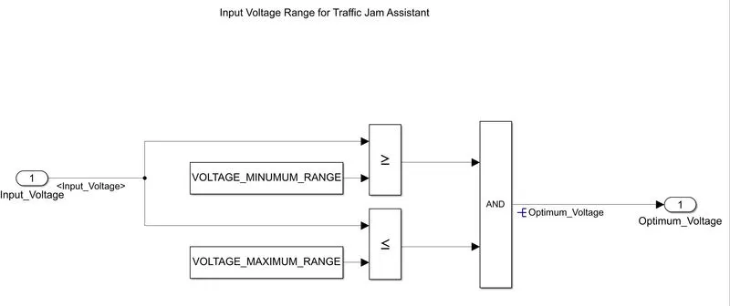
Figure 3: VoltageLimit Subsystem
Requirement No 2 : Display Unit Subsystem
Inputs Signals:
- Enable_Display
- Input_Switch
- Optimum_Voltage
Output Signal: Output_Display
Logic:
- Signal “Enable_Display” must be saturated between the range 0 – 7.
- Input Signal “Enable_Display” is compared against predefined set of values in a multiport switch.
- Total data ports in the multiport switch is 5.
- Multiport switch inputs 1 & 2 is connected to calibration signal “ON_MODE”.
- Multiport switch inputs 3 & 4 is connected to calibration signal “OFF_MODE”.
- Multiport switch input 5 is connected to calibration signal “STANDBY_MODE”.
- The output from Multiport switch is connected to the first input port of the Switch block.
- The third input port of the Switch block is connected to the calibration signal “NO_DISPLAY”.
- NOT value of input signal “Input_Switch” is compared in an AND gate against input signal “Optimum_Voltage”
- The output from comparing if calibration signals “INTERRUPT_1” & “INTERRUPT_2” are equal.
- The output of the AND gate is the second input of the switch block.
- The output from the switch block is “Output_Display”.
Based on the above logic the Display Unit Subsystem is modelled in MATLAB Simulink as per MAAB guidelines
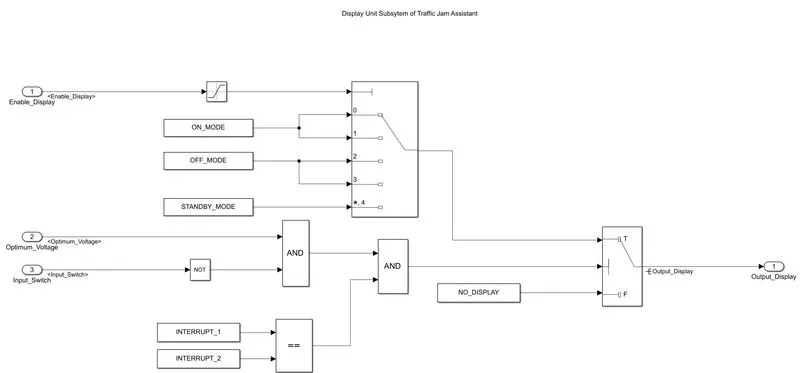
Figure 4: Display Unit Subsystem
Step 2: Creation of a Simulink Data Dictionary of the model
- The Model Explorer is used in which, link to data dictionary option is selected to create, modify, and view the entries in a data dictionary
- Here the access to base workspace is disabled as the requirement of data has already been provided and that data must be used for data referencing.
- Based on the SLDD-XLFormat file provided a Simulink Data Dictionary file sldd.
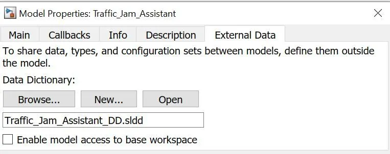
Figure 5: Creation of new SLDD file
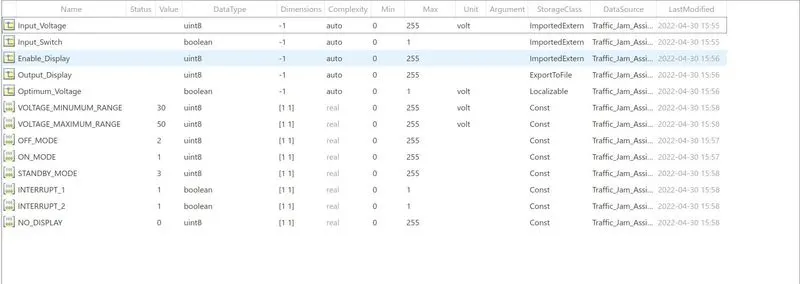
Figure 6: SLDD file for Traffic Jam Assistant
For code generation,
- Storage class for Input signals: ImportedExtern;
- Storage class for Output signal: Export to File;
- Storage class for local signals: localizable;
- Storage class for calibration signals: Const.
Main Advantage of using SLDD is it reduces repeatable initialisation or declaring init file for the parameters or signals in current model.
The input, output signals and constant parameters can be directly linked from the SLDD file to the Simulink Model.
Step 3: Model Advisor Check
- The Model Advisor checks the model or subsystem for modelling conditions and configuration settings that cause inaccurate or inefficient simulation of the system that the model represents.
- The Model Advisor checks helps to verify compliance with industry standards and guidelines.
- By using the Model Advisor, we can implement consistent modelling guidelines across projects and development teams.
here in this project, MAAB (MathWorks Automotive Advisory Board Standards) is used to check the modelling conditions and required errors are minimized to abide to the guidelines or Standards of the MAAB
The detailed report is generated in HTML file after minimising the errors or warnings

Figure 7: Model Advisor Report for Traffic Jam Assistant as per MAAB Guidlines
Step 4: Code Generation
After building the Simulink model to determine the correctness of the model as per the MAAB guidelines Model Advisor Check is done and report is generated without errors
Using Embedded coder(ert.tlc) Code generated for the above Simulink model which can be used for the verification of code for Software in Loop Testing (SIL) and Hardware in Loop Testing (HIL)
Procedure for Code Generation
a) Configuration of Solver Settings for Code generation
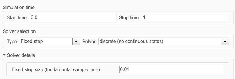
Figure 8: Solver Settings for Code Generation
Here the in the model configuration settings, In Solver selection
- Solver – Fixed-Step
- Solver Type – Discrete (no continuous states)
- Fixed Step size – 0.01
b) Configuration of code Generation Settings
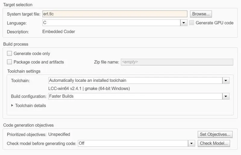
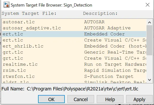
Figure 9: Code Generation parameters
Here the in the model configuration settings, For Code Generation
- System Target File: Embedded Coder (ert.tlc) is selected as target file, to generate a Template of the current model for SIL Testing.
- The Floating-point numbers are enabled to use the parameters or signals in SLD.
c) Atomic Subsystem of the Traffic_Jam_Assistant
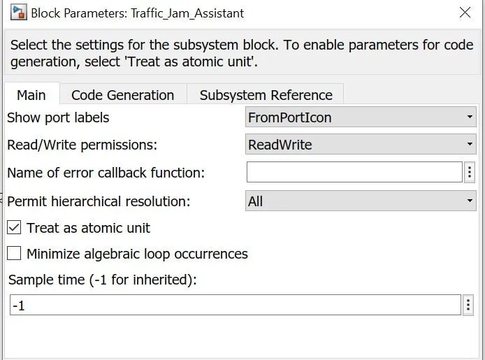
Figure 10: Block parameters of Traffic_Jam_Assistant
- Block properties of the subsystem is set to Treat as an Atomic unit.
- The values or parameters which are defined are confined to this particular atomic subsystem when it is treated as atomic unit.
d) Embedded C Code Generation using Embedded coder in MATLAB Apps section
- Embedded Coder (ert.tlc), is used to generate a code for the Traffic_Jam_Assistant.
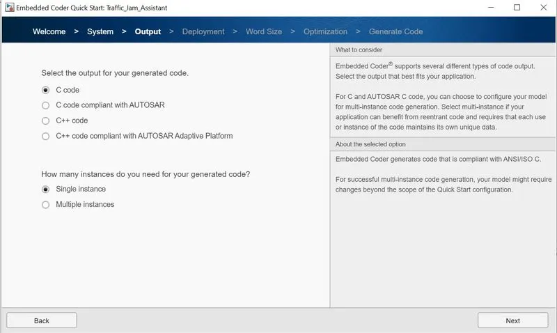
- A quick start guide is used for code generation is which helps to build the model and generate corresponding (.h, .c, rtwtypes.h) formats.
- Quick Start guide for Embedded C Code Generation
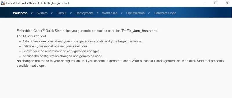
- Traffic_Jam_Assistant main Subsystem is considered here for code generation.
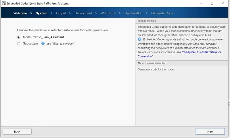
- C code is generated as Output and it is generated in Single instance
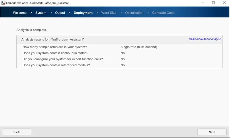
- Deployment of the above mode is done at single sample rate 0.01
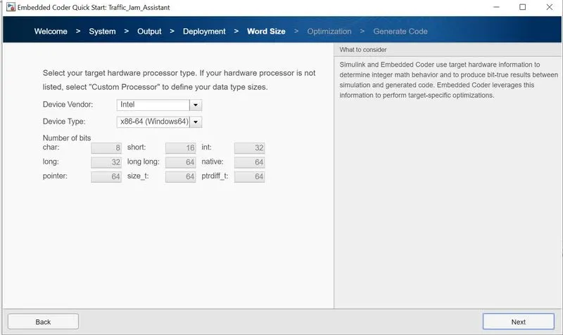
- The target hardware processor type is selected by default by the current system as below
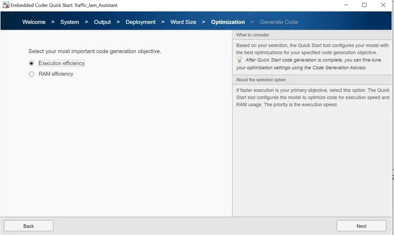
- The objective of code generation is set to Execution Efficiency for optimization.
- Code generation parameters for above model are shown as below
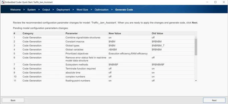
- Code generation is completed successful and the codes can be viewed in code generation report
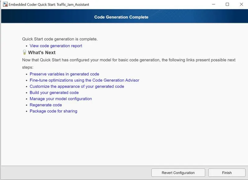
Conclusion:
- Hence Traffic Jam Assistant algorithm was implemented in MATLAB Simulink as per MBD guidelines.
- A Simulink Data Dictionary for the above model is created and mapped it to the current model.
- A Model Advisor Report for the current model as per MAAB Guidelines without errors
- Embedded C code is generated use using Embedded Coder (ert.tlc) for the Traffic Jam Assistant model