Project 1 (Mini Project on Vehicle Direction Detection
AIM:
- To Develop Vehicle Direction Detection feature as per the Requirement Document using MATLAB Simulink.
- To perform all the MBD related processes: Requirement Tagging & Traceability, SLDD creation, Configuration Parameter changes, Model Advisor check & Code Generation.
Simulink Model
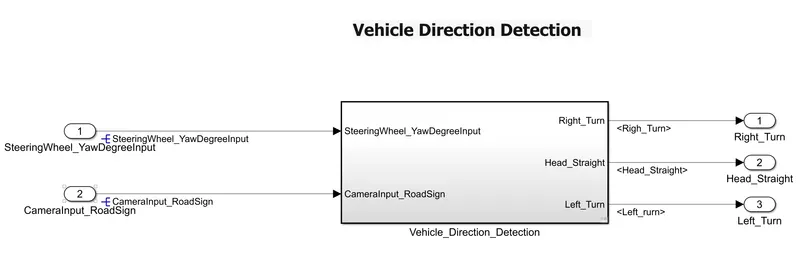
Figure 1a Simulink Model for Vehicle Direction Detection
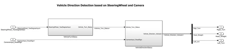
Figure 1b Simulink Model of Vehicle Direction Detection Subsytem
Requirement Analysis and Tracebillity
- Based on the Requriements provided, the Inputs, Outputs and control logic is been decided.
- Requirement Analysis is a very useful method or tool as it simplifies the problem based on what requirements are need to implement the algorithm.
- All the requriements are Defined in Word File and by building the Model Based on the requreiments it is the fastest way to achieve a solution to the problem.
- Requirements traceability connects models, tests, and code with requirement definitions to help manage change and reduce waste in the design life cycle.
Vehicle Direction Detection has 2 main requirements
- Vehicle Turn Status
- Vehicle Direction Status
1.Vehicle Turn Status
Identifying the direction of the vehicle is one of the important & diverse features in Autonomous driving & Advanced Driver Assistance Features.
In this particular sub-feature of identifying the direction of vehicle is basically identifying the direction the vehicle is based on the Steering wheel rotation status
Input
Steering wheel input as yaw rate (SteeringWheel_YawDegreeInput) is the input for this system.
Output
Vehicle_Turn_Status
Logic
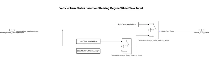
- SteeringWheel_YawDegreeInput is compared against 3 angular values, one each for left turn, right turn & straight drive to say which specific direction the steering wheel is turning towards.
- Using switch blocks a logic is build to compare the input with the Calibration Values: Right_Turn_AngularLimit, Left_Turn_AngularLimit, Straight_Drive_Steering_Angle
2. Vehicle Direction Status
Inputs
- Vehicle_Turn_Status
- Camera (CameraInput_RoadSign), which confirms the occurrence of a road sign.
Output Vehicle_Direction_Indicator
Logic
- Signal Vehicle_Turn_Status is compared against calibration values (Calibration Values: RightTurn_RoadSign, LeftTurn_RoadSign, Straight_RoadSign),
- If each of them is found equal, then each of the three corresponding output is compared against the camera input signal,
- Using OR logical operator block the Vehicle Turn and Camera signal are compare and using MUX the 3 outputs are muxed and connected to the Vehicle_Direction_Indicator
- A signal conversion block is used to convert the all the signals of different data types to boolean.
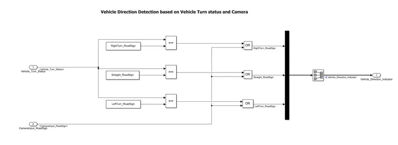
The Output Vehicle_Direction_status is demuxed and the vehicle Direction is detected by observing it through scope (Right_Turn, Head_Straight, Left_Turn ) direction is determined
Creation of Simulink Data Dictionary
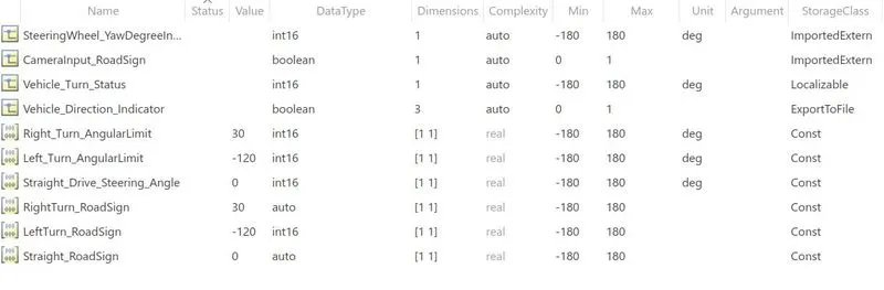
- The Model Explorer is used in which, link to data dictionary option is selected to create, modify, and view the entries in a data dictionary
- Here the access to base workspace is disabled as the requirement of data has already been provided and that data must be used for data referencing.
- Based on the SLDD-XLFormat file provided a Simulink Data Dictionary file Vehicle_Signal_Calibration_Data.sldd
For code generation,
- Storage class for Input signals: ImportedExtern;
- Storage class for Output signal: Export to File;
- Storage class for local signals: localizable;
- Storage class for calibration signals: Const.
Main Advantage of using SLDD is it reduces repeateble initilasation or declaring init file for the parameters or signals in current model.
These parameters or signals can be directly linked to the SLDD file which not
Model Advisor :
- The Model Advisor checks the model or subsystem for modeling conditions and configuration settings that cause inaccurate or inefficient simulation of the system that the model represents.
- The Model Advisor checks helps to verify compliance with industry standards and guidelines.
- By using the Model Advisor, we can implement consistent modeling guidelines across projects and development teams.
here in this project, MAAB (MathWorks Automotive Advisory Board Standards) are used to check the modelling conditons and required errors are minimized in order to abid to the guidlines or Standards of the MAAB
The detailed report is generated in HTML file after minimising the errors or warinings to less than 15.

Model in Loop (MIL) Testing
Model in Loop testing is a systematic method to generate test cases from models based on the Requirement Analysis. It used to evaluate requirements independent of algorithm design and development.
Model-based testing involves:
- Creating a model of system requirements for testing
- Generating test data from this requirements using MIL Testing
- In model-based testing, we use requirement analysis to generate test cases to verify your design.
- This process also helps automate other verification tasks and streamlines the review process by linking test cases and verification objectives to high-level test requirements.
- By building a simulink model we can analyze traceability between requirements, design, generated code, and test.
3. Verifying the design algorithm with generated test cases
- Using Simulink can manage the test cases and systematically execute them to confirm that your design meets requirements.
- code coverage metrics to assess the completeness of the MIL testing which can identify the missing requirements and functionalities.
Procedure for MIL Testing by generating a Test Harness file
Step 1: Configuration of Model Settings for MIL Testing
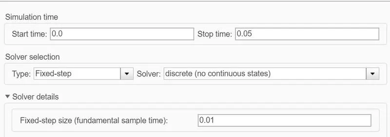
Figure6: Solver Settings for MIL Testing
Here the in the model configuration settings, In Solver selection
- Solver - Discrete
- Solver Type - Fixed Step 0.01s
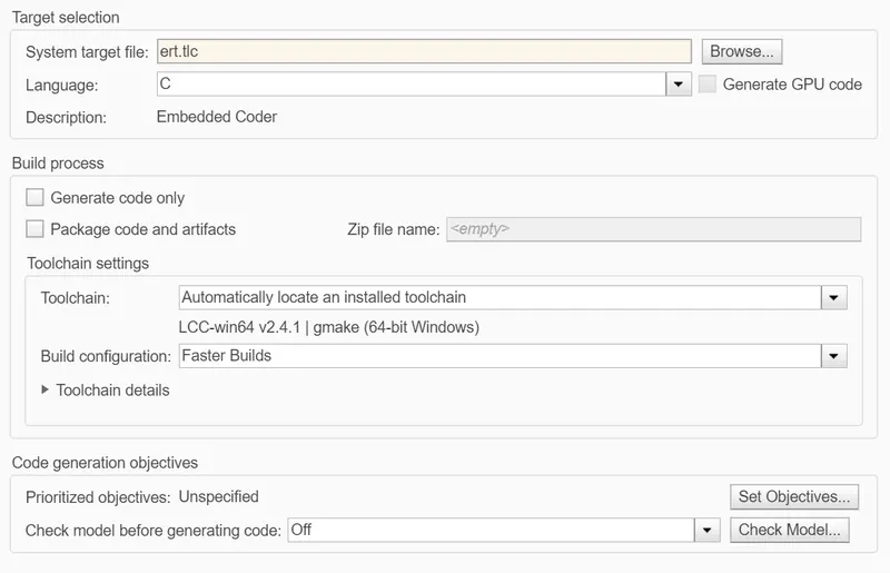
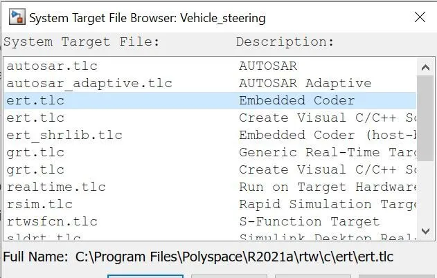
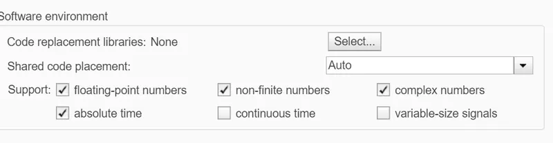
Figure 7: Code Generation parameters for MIL Testing
Here the in the model configuration settings, For Code Generation
- System Target File: Embedded Coder (ert.tlc) is selected as target file, to generate a Template of the current model for MIL Testing.
- here the Floating-point numbers are enabled so as to use the parameters or signals in SLDD
Step 2: Atomic Subsystem of Vehicle_Direction_Detection
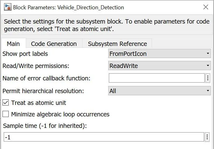
Figure8 : Block parameters of Vehicle_Direction_Detection
- An Subsystem for the model is been created and it is block properties of the subsytem is set to Treat as an Atomic unit.
- The values or parameters which are defined are confined to this particular Atomic subsytem when it is treated as Atomic unit.
Step 3: Creation of Test Harness File for MIL Testing for the Vehicle_Direction_Detection
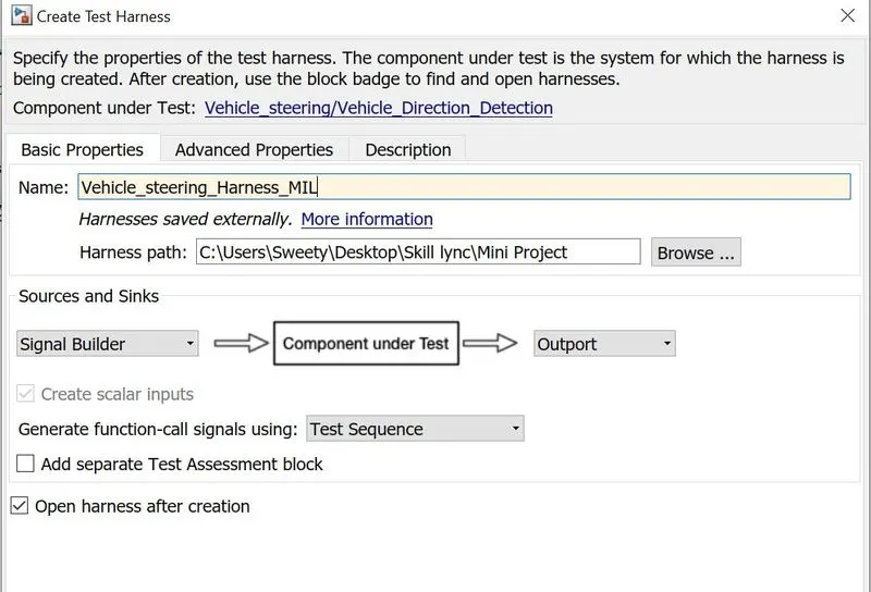
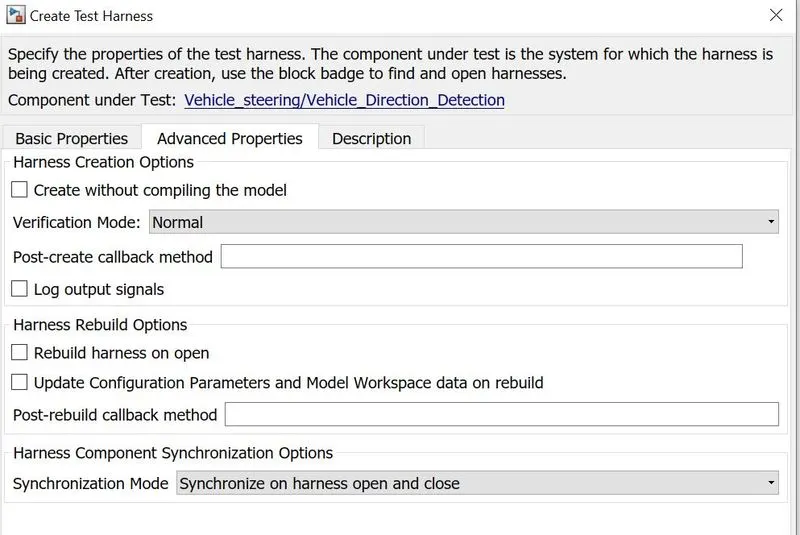
Figure 9: Block parameters for Test Harness Creation
This is an important step for MIL Testing,
The block parameters of creation of Test harness are set as below
- Source - Signal Builder
- Sink - Outport
- Harness Creation options - Normal mode as verification mode
Other parameters are set to inheritly, By setting the above parameters, a Test Harness file is created for MIL Testing,
Fix the errors displayed by Diagnostic Viewer and also check Model Advisor Tool.
Step 4: Internal Test Harness File of Vehicle_Direction_Detection
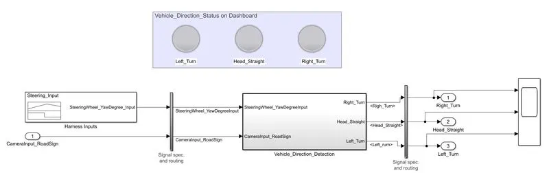
Figure 10: Simulink Model of Internal Test Harness File for Vehicle_Direction_Detection
Test Harness Input
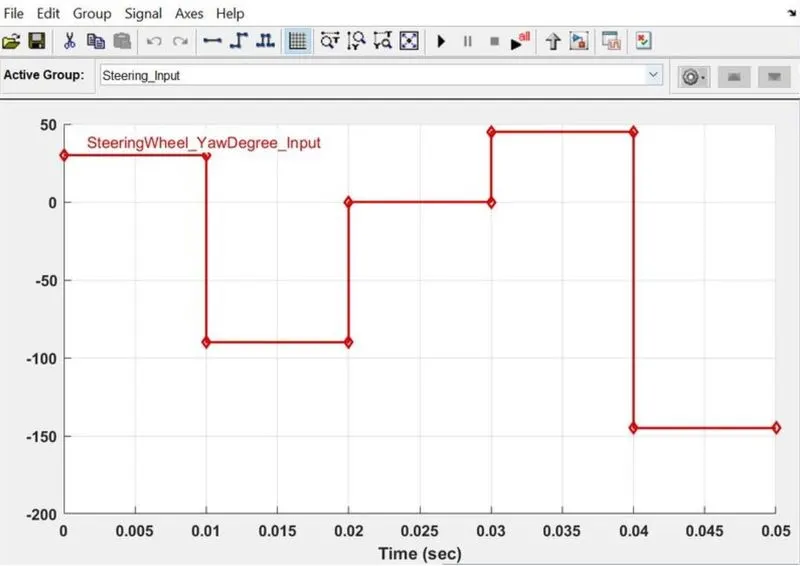
- Signal Builder block is considered in which the SteeringWheel_YawDegreeInput2.xls file is imported into signal builder.

- This Signal builder is given as input for the current model for MIL testing with the test case file loaded.
- It describes the transistion at particular test case corresponding to the predefined logic.
Test Harness Output
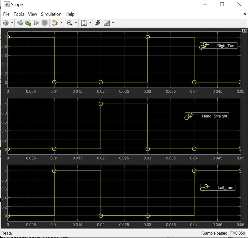
- The scope is used to plot the Left_Turn, Head_Straight and Right_turn form Vehicle Direction_Indicator to show how the system is responding to the inputs
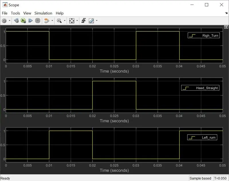
After building the simulink model in order to determine the correctness of the model which is build a Model In Loop Testing is done first with the defined functional test cases.
If the result found satisfactory then it is send to further higher stages for Software in Loop Testing and Hardware in Loop Testing.
Here in this model our Aim is to generate a code not to do SIL Testing.
Software-in-the-loop (SIL) Testing and Code Generation
- A software-in-the-loop (SIL) simulation compiles generated source code and executes the code as a separate process on the computer.
- During a SIL simulation, we can collect code coverage and execution-time metrics for the generated code.
Procedure for Software In Loop (SIL) Testing by generating a Test Harness file
Step 1: Configuration of Model Settings for SIL Testing
Figure11: Solver Settings for SIL Testing
Here the in the model configuration settings, In Solver selection
- Solver - Discrete
- Solver Type - Fixed Step 0.01s
Figure 12: Code Generation parameters for SIL Testing
Here the in the model configuration settings, For Code Generation
- System Target File: Embedded Coder (ert.tlc) is selected as target file, to generate a Template of the current model for SIL Testing.
- here the Floating-point numbers are enabled so as to use the parameters or signals in SLDD
Step 2: Atomic Subsystem of the Vehicle_Direction_Detection
Figure 13: Block parameters of Vehicle_Direction_Detection
- An Subsystem for the model is been created and it is block properties of the subsytem is set to Treat as an Atomic unit.
- The values or parameters which are defined are confined to this particular Atomic subsytem when it is treated as Atomic unit.
Step 3: Creation of Test Harness File for SIL Testing for the Vehicle_Direction_Detectionl
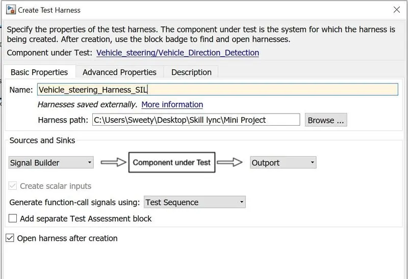
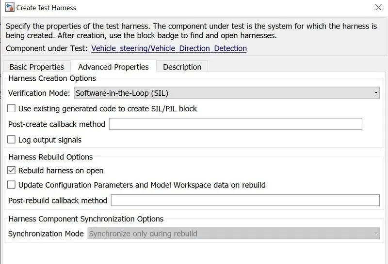
Figure 14 : Block parameters for Test Harness Creation
This is an important step for SIL Testing,
The block parameters of creation of Test harness are set as below
- Source - Signal Builder
- Sink - Outport
- Harness Creation options - Software in Loop as verification mode
Other parameters are set to inheritly, By setting the above parameters, a Test Harness file is created for SIL Testing,
Fix the errors displayed by Diagnostic Viewer and also check Model Advisor Tool.
Step 4: External Test Harness File of Vehicle_Direction_Detection
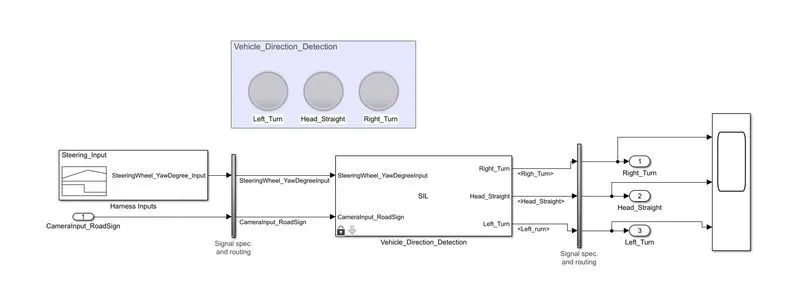
Figure 15: Simulink Model of External Test Harness File for Vehicle_Direction_Detection
S function Logic
- An S-function is a computer language description of a Simulink block written in MATLAB, C, C++, or Fortran. C, C++, and Fortran S-functions are compiled as MEX (Matlab Executable ) files using the
mexutility - As with other MEX files, S-functions are dynamically linked subroutines that the MATLAB execution engine can automatically load and execute.
- S-functions use a special calling syntax called the S-function API that uses to interact with the Simulink engine.
- This interaction is very similar to the interaction that takes place between the engine and built-in Simulink blocks.
- Embedded Coder (ert.TLC), is used for S-functions in a model to generate a code for the Sign Detection Logic Subsystem.
- After Creation of Test Harness file the parameters inside the sfunction are not tunable, in order to do so we have change in the main subsytem and repeat the code generation again.
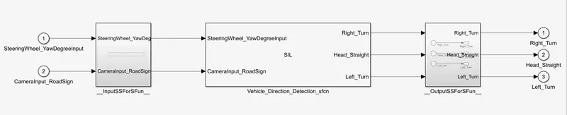
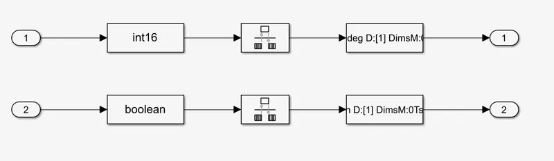
Signal Routing Subsystem
Input Signal Routing Subsystem
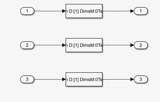
- This subsystem has been created by Simulink to adapt the output of Signal builder blocks to the inteface required by the harness component.
- Any attempt in modifyong the contents of this subsystem may result in compliation and simulation failure
Output Signal Routing Subsystem
- This subsystem has been created by Simulink to adapt the output of the harnessed component to the inteface required by the sink block.
- Any attempt in modifying the contents of this subsystem may result in compliation and simulation failure
st Harness Input
- Signal Builder block is considered in which the SteeringWheel_YawDegreeInput2.xls file is imported into signal builder.
- This Signal builder is given as input for the current model for SIL testing with the test case file loaded.
- It describes the transistion at particular test case corresponding to the predefined logic.
Test Harness Output
- The scope is used to plot the Left_Turn, Head_Straight and Right_turn form Vehicle Direction_Indicator to show how the system is responding to the inputs
Working of The Vehicle_Direction_Detection Logic:
- An input from the Signal Builder is given as SteeringWheel_YawDegreeInput.
- The input value is compared using Switch Blocks with the predefined Calibration values based on the requiremens.
- Based on the conditions defined in switch block, it activates the corresponding constant block by switching it based on the threshold value.
- For threshold condition~= Straight_Drive_Steering_angle - is set for lower switch blocks Left_Turn_AngularLimit (true) and Straight_Drive_Steering (False)
- For threshold condition> Straight_Drive_Steering_angle - is set for upper switch blocks (for Left_Turn_AngularLimit (true) and Output from Lower Switch block is propagated (False)
- The Output Signal Vehicle_Turn_Status is compared against calibration values (Calibration Values: RightTurn_RoadSign, LeftTurn_RoadSign, Straight_RoadSign),
- If each of them is found equal, then each of the three corresponding output is compared against the camera input signal,
- Using OR logical operator block the Vehicle Turn and Camera signal are compare and using MUX the 3 outputs are muxed and connected to the Vehicle_Direction_Indicator.
- A signal conversion block is used to convert the all the signals of different data types to boolean.
- The Output Vehicle_Direction_status is demuxed and the vehicle Direction is detected by observing it through scope (Right_Turn, Head_Straight, Left_Turn ) direction is determined.
- An interactive screen (Here Lamps block is used) is designed on the dashboard where the driver can see his screen and act accordingly based on the logic.
- The simulation pacing option is enable to 0.01 sec to see these transitions on Driver dashboard Screen.
Ex :
- Consider When the input is -30, the time of simulation is between 0.01 to 0.02 sec.
- The input is feed to Vehicle_Turn_Status subsystem, which is compared to the switch blocks.
- As the input, -30 ~= threshold condition (1 boolean ) which activates the corresponding constant Left_Turn_Angular_Limit is send as output to the Vehicle_Turn_Status.
- The Vehicle_Turn_Status is compared with LeftTurn_RoadSign and it is compared with CameraInput_RoadSign and given to Vehicle_Direction_Indicator.
- In Vehicle_Direction_Indicator activates the corresponding lamps Left_Turn=1, Right Turn=0, Head_Straight =0 Outputs are set using the Mux it is sent to the Demux.
- This output can be seen in the Driver dashboard Screen and accordingly the Vehicle Direction is calibrated by the driver.
Conclusion:
- Henc a Vehicle Direction Detection feature as per the Requirement Document is developed using MATLAB Simulink.
- All the MBD related processes: Requirement Tagging & Traceability, SLDD creation, Configuration Parameter changes, Model Advisor check & Code Generation was performed to above model and saved in the attached files.
- In Configuration Parameters: we enabled “Support Floating Numbers” under Code Generation settings.
- Hence a Model In Loop (MIL) , Software In Loop (SIL) Test Environment and Code Generation( Using Embedded Coder ertc.tlc) with functional test cases is succesfully created for the Vehicle_Direction_Detection.