Project 1- Traffic Jam Assistant Feature
Traffic Jam Assistance System
- Root System:
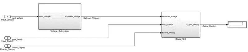
Figure 1: Root System
- The above figure represents the Traffic_Jam_Assistance system.
- It has two subsystems:
- Voltage_Subsystem
- DisplayUnit Subsystem
- The Traffic_Jam_Assistance system has three inputs Input_Voltage, Input_Switch and Enable_Display and one output Output_Display.
- Voltage_Subsystem:
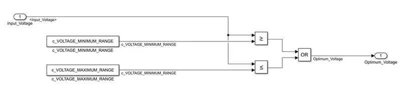
Figure 2: Voltage_System
- The above figure represents Voltage_Subsystem.
- The Voltage_Subsystem has one input Input_Voltage and one output Optimum_Voltage.
- In this subsystem the input voltage is checked with input voltage limits.
- The Input_Voltage is compared with two constants VOLTAGE_MINIMUM_RANGE and VOLTAGE_MAXIMUM_RANGE and the outputs of these two comparisons is given to a OR block.
- The Input_Voltage must be greater than or equal to VOLTAGE_MINIMUM_RANGE OR less than or equal to VOLTAGE_MAXIMUM_RANGE.
- The output of this subsystem is Optimum_Voltage which is the output of the OR block.
- DisplayUnit Subsytem:
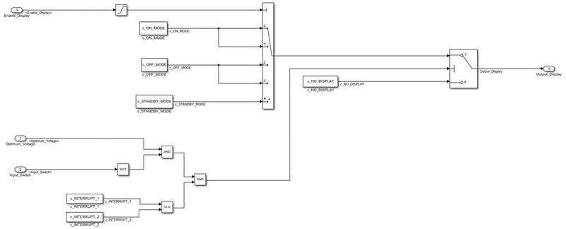
Figure 3: DisplayUnit Subsystem
- The above figure represents the DisplayUnit subsystem.
- The subsystem has three input ports, six constant blocks, a multiport switch block, switch block, logical operator blocks and one output port.
- The constant blocks are ON_MODE, OFF_MODE, STANDBY_MODE.
- The above constant blocks are given to the multiport switch block as inputs.
- The Diagnostic for default case is set to warning and the data port order is set to Zero-based contiguous as shown in Figure 4.
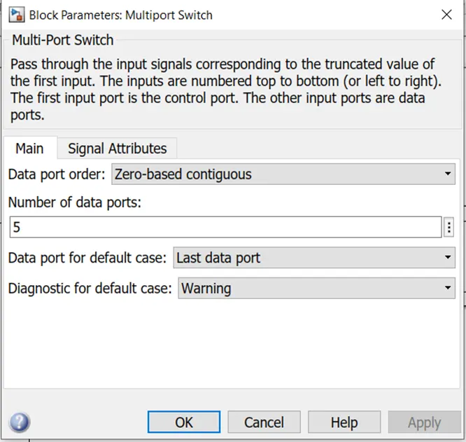
Figure 4: Multiport Switch settings
- Interrupt_1 and Interrupt_2 are given to relational operator block.
- No_Display block is given to the switch block as a second input.
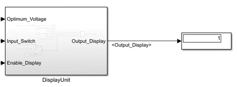
Figure 5: Output of the system
- The above figure represents the output of the system.