Project 1- Traffic Jam Assistant Feature
Problem Statement:
To develop one specific requirement of Traffic Jam Assistant algorithm which would predominantly feature in the IPC algorithm.Please note that the whole Traffic Jam Assistant is a very huge algorithm & only one small part of the logic is implemented here. Idea is to familiarize with concepts of Model Based Development in MATLAB Environment. The Project must be done keeping in mind the following processes & steps.
- This model must be developed in MATLAB Simulink as per MBD guidelines.
- Code Generation Profile must be in Embedded Coder.
- Simulink Data Dictionary must be created for the model & must be linked to the model.
- Model Advisor Report is mandatory & this will be followed by Code Generation.
Input Signals:
|
Name of the Signal |
Data Type |
Range |
|
Input_Voltage |
uint8 |
0 - 255 |
|
Input_Switch |
boolean |
0 – 1 |
|
Enable_Display |
uint8 |
0 - 255 |
Output Signal:
|
Name of the Signal |
Data Type |
Range |
|
Output_Display |
uint8 |
0 - 255 |
Calibration Signals:
|
Name of the Signal |
Data Type |
Range |
Initial Value |
|
VOLTAGE_MINIMUM_RANGE |
uint8 |
0 – 255 |
30 |
|
VOLTAGE_MAXIMUM_RANGE |
uint8 |
0 – 255 |
50 |
|
OFF_MODE |
uint8 |
0 – 255 |
2 |
|
ON_MODE |
uint8 |
0 – 255 |
1 |
|
STANDBY_MODE |
uint8 |
0 – 255 |
3 |
|
INTERRUPT_1 |
boolean |
0 – 1 |
1 |
|
INTERRUPT_2 |
boolean |
0 - 1 |
1 |
|
NO_DISPLAY |
uint8 |
0 – 255 |
0 |
Local Signal:
|
Name of the Signal |
Data Type |
Range |
|
Optimum_Voltage |
boolean |
0 - 1 |
Requirement No 1:
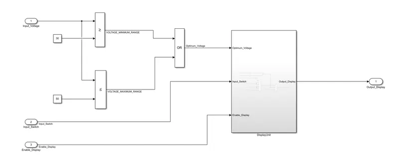
- Input Signal “Input_Voltage” is compared against voltage values “VOLTAGE_MINIMUM_RANGE” & “VOLTAGE_MAXIMUM_RANGE”.
- Incoming input signal “Input_Voltage” must be greater than – equal to “VOLTAGE_MINIMUM_RANGE” and less than – equal to “VOLTAGE_MAXIMUM_RANGE”.
- Output signal from here is “Optimum_Voltage” which will be one of the inputs to the subsystem “DisplayUnit”.
Requirement No 2 (DisplayUnit Subsystem):
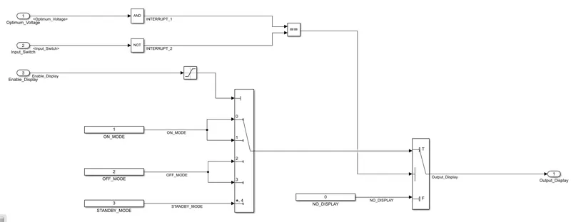
- Input Signals are “Optimum_Voltage”, “Input_Switch”,“Enable_Display”. Signal “Enable_Display” must be saturated between the range 0 – 7. Output signal from the subsystem is “Output_Display”.
- Input Signal “Enable_Display” is compared against pre – defined set of values in a multiport switch. Total data ports in the multiport switch is 5.
- Multiport switch inputs 1 & 2 is connected to calibration signal “ON_MODE”, Multiport switch inputs 3 & 4 is connected to calibration signal “OFF_MODE” while Multiport switch input 5 is connected to calibration signal “STANDBY_MODE”.
- The output from Multiport switch is connected to the first input port of the Switch block. The third input port of the Switch block is connected to the calibration signal “NO_DISPLAY”.
- Meanwhile NOT value of input signal “Input_Switch” is compared in an AND gate against input signal “Optimum_Voltage” and the output from comparing if calibration signals “INTERRUPT_1” & “INTERRUPT_2” are equal. The output of the AND gate is the second input of the switch block.
- The output from the switch block is “Output_Display”.
Solution:
- Based on the requirement no 1, the 'Input_Voltage' is compared against the voltage values voltage minimum range and voltage maximum range. The input signal 'Input_Voltage'is greater than equal to voltage minimum range and less then equal to voltage maximum range. 'Output_Voltage' is one of the inputs to the 'DisplayUnit'.
The input signals for subsystem DisplayUnit are Optimum voltage, Input switch and Enable display. The third input signal enable display is saturated between 0-7. The DisplayUnit subsystem is modelled according to the requirement 2 as shown below.
The developed model is according to the Model based development guidelines.
- MAAB (Mathworks Automotive Advisory Board) Guidelines:
MAAB guidelines actually originate to coordinate the key feature requests from important tier 1 OEMs in the automotive industry. The very first modelling guidelines are released in 2001. The aim here is to set rules and guidelines for modelling a system in Simulink, Stateflow. It mainly focuses on the format and style of system blocks. These guidelines makes it easy to develop, document and maintain the control algorithm models used in the production of development software.
By following the MAAB guidelines, it is easy to achieve:
1) Fast software changes
2) Simple and effective processes
3) Reusable and readable models
4) Cooperation with tier 2 and tier 3 contractors
5) Easy transition of pre-developed projects to product development
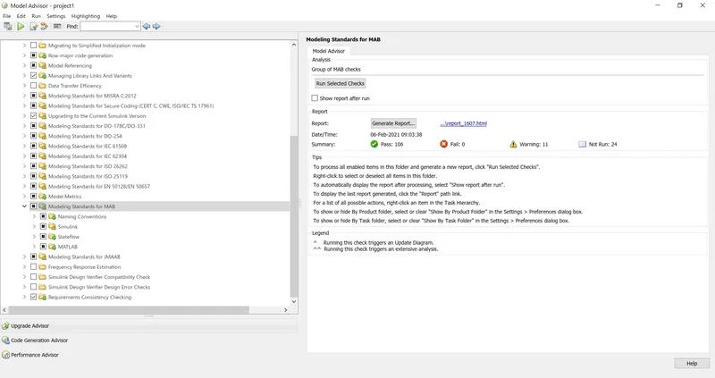
In the given project, almost all the MBD MAAB guidelines are followed and no failures are achieved. An attempt is made to reduce the warning signs as much as possible. The MBD guidelines can be cross checked by viewing the generated report in the model.
- Simulink Data Dictionary:
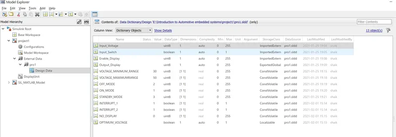
Simulink data dictionary is a data repository where model relevant data can be stored and linked to it so that it can be used whenever necessary. It contains the design data of the model such as input signals, calibration signals and output signals. Design data has the information such as data type, dimension, value range, initial value. One robust simulink data dictionary can be linked to number of model which share common signal information. As a part of the project, data dictionary is created and linked to the developed model. The information related to the design data is shown below:
- Model advisor report:
The next task in the project is to generate a model advisor report. Model advisor checks relate to simulink are performed and the report is generated with no fail checks and minimised warning checks.
- Code generation:
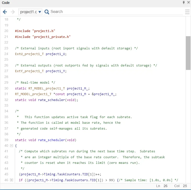
The developed model is imported into the embedded coder platform and the model is built. After changing some model setting, code is generated in c/c++ format. the .c file of code can be found in the generated code report or it can be viewed in the embedded coder.
- Model-in-Loop testing:
In the model based software development, MIL is the simulation of an embedded system. This is one of the earliest stages of developing a software. Model which has to be simulated exists entirely in native simulation tool. (in our case Simulink). This mode of testing is best suitable for control algorithm development.
In short, if the developed embedded model is simulated together with the environment model, it is called MIL simulation testing.
In addiiton to the code generation, Model-in-loop testing is also performed for the model.
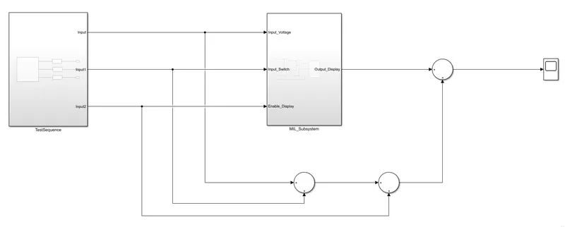
The model can be examined in detail in Simulink. For MIL testing of the model, MC/DC coverage is analysed.