Project 1 - Review of Shear & Moment Connections in RAM Connection
PROJECT 1
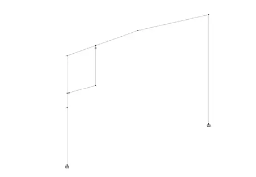
Design and optimize typical shear, moment and splice joints in RAM connection for the following structure modelled in Staad Pro. Design and optimize base plate connection.
Structure: A 2D portal frame fixed suppoet spanning 15m with a pitched roof ridge height of 12m, slope of 4 degrees. A uniformly distributed load of 10kN/m is applied on the roof beams. Optimize the beams and columns for 85% utilization and consider splice joints at 6m from base and 4m from beam column joints. Consider a hanger bram shear connected with column support of 4m height from the splice joint with a length of 3m from beam-column corner joint carrying 5kN/m load. Use hot rolled sections.
Solutions:
- WORKING OUT M 18 DIAMETER BOLTS
- Considering the Bolt D@B diameter of 18 mm
- BOLT HOLE DIAMETER D@H= 20+2 = 20 MM
- Bolt G.8.8
- 800 N/MM^2 is F@UB.
- F@Y is equal to 640 N/MM^2.
- GETTING PLATE RIGHTS
- F@UP is equal to 410 N/MM^2.
- F@Y = 250 N/MM^2
- EDGE MINIMUM DISTANCE = 1.5 * D@0 = 1.5 * 20 = 30 MM
- Max Edge Distance = 12 * T * Epsilon = 12 * 8 * 1 = 96 mm
- SQRT(250/F@Y)=SQRT(250/250)=1 is EPSILON.
- PITCH MINIMUM DISTANCE = 2.5 * D = 2.5 * 18 = 45 MM
- MAXIMUM PITCH DISTANCE: 128 mm = 16 * T = 16 * 8
- MAXIMUM GAUGE DISTANCE: 132 mm is equal to 100+4*T= 100+4*8.
- THE M 20 DIAMETER BOLT CALCULATION
- Considering Bolt D@B's diameter of 20 mm
- BOLT HOLE DIAMETER D@H= 20+2 = 22 MM
- Bolts G.8.8
- 800 N/MM^2 is F@UB.
- F@Y is equal to 640 N/MM^2.
- GETTING PLATE RIGHTS
- F@UP is equal to 410 N/MM^2.
- F@Y = 250 N/MM^2
- EDGE MINIMUM DISTANCE = 1.5 * D@0 = 1.5 * 22 = 33 mm
- HIGHEST EDGE DISTANCE = 12 * T * EPSILON = 12 * 10 * 1 = 120 mm
- SQRT(250/F@Y)=SQRT(250/250)=1 is EPSILON.
- PITCH MINIMUM DISTANCE = 2.5 * D = 2.5 * 20 = 50 mm
- PITCH MAXIMUM DISTANCE = 16 * T = 160 mm
- ULTIMATE GAUGE DISTANCE = 100 + 4 * T = 100 + 4 * 10 = 140 mm
Open STAAD PRO
CHOOSE THE ANALYTICAL MODEL TYPE AND THE METRIC UNIT.
Step 1.
Open Staad.pro
Describe geography
USE X, Y, AND Z as node data in meter
Step 2.
Define Material
Steel
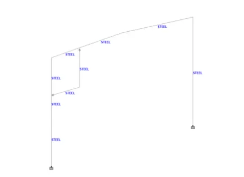
Step 3
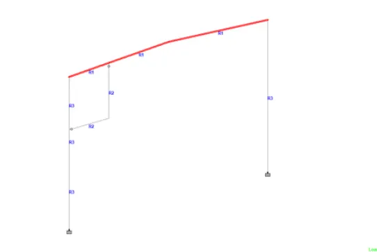
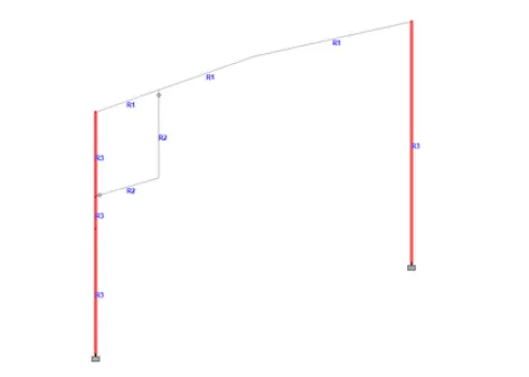
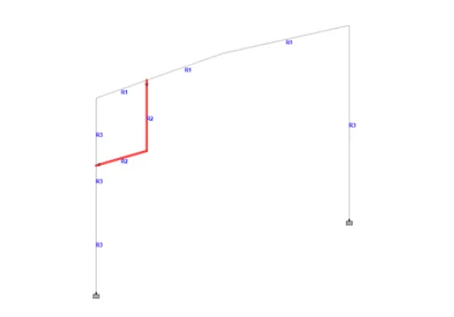
Define Property
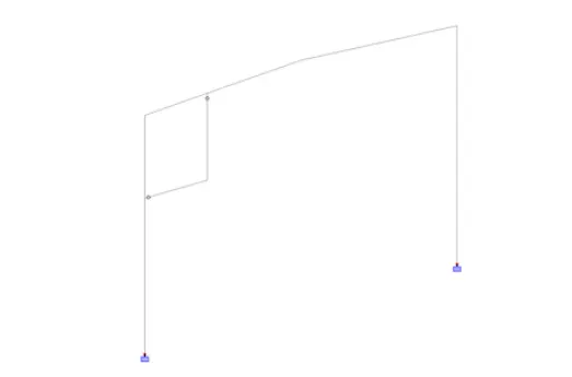
Rafter ISMB 600
Column ISWB 600
Stub column and supporting beam ISLB 200
Step 4
Define support condition
Fixed
Step 5
Define Specifications
Release, start MZ, MY then end MY, MZ
Step 6
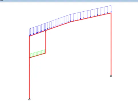
Define Load in direction Y
Define load cases
Self weight load = 1.1
Dead Load = 1
Define Live Load
Member load,
Uniform force = -10kN/m in direction GY
Step 7
Define load combination
1.5 LL + 1.5 DL
DL=1.5 is the load factor.
LOAD FACTOR LL: 1.5
Step 8
Go to analysis in Ribbon tool bar
Perform analysis -> print all
Go to Design -> Desine parameters -> post processing mode -> Utilization ratio -> Click connection design
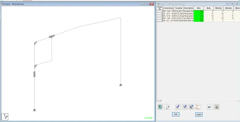
CONNECTION: 1
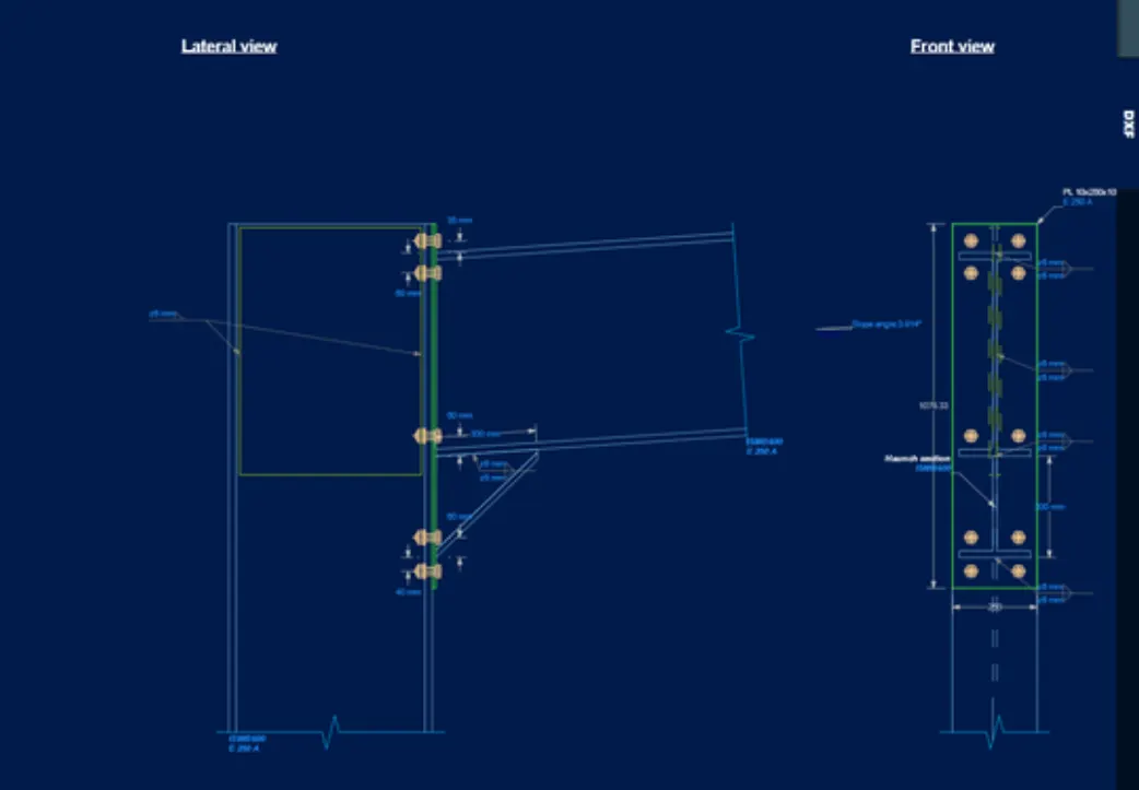
Select Member -> Click Basic connection -> select design code iS800 2007 -> Connection design -> Moment end plate BCF - Haunch -> Angle/Haunch moment beam column flange
check slip resistance as NO
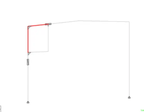
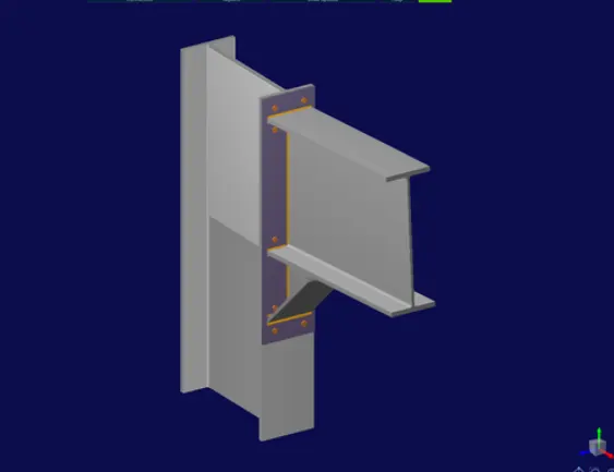
Type of Member: Prismatic Member
Section: ISMB 600
H 250 A is the material.
Axial Angle = Zero
ANGLE VERTICAL = 3.814
YES FOR THE BEAM MINI HUNCH
MINI BEAM HAUNCH
Section: ISMB 600
A starting height of 300 mm
LENGTH: 300 millimeters
VISIT THE MEMBERS
Verify the column specifications.
SECTION SELECTED AS INDIAN
ISWB 600 is the section.
E 250 A is the material.
COLUMN END = AGREE
TAB BEAM SIDE
Type of Top Fold Weld: Fillet
WELD AT TOP FLANGE = E41
WELD SIZE OF TOP FLANGE = 6 MM
Type of Bottom Flange Weld: Fillet
FLAG AT THE BOTTOM = E41
SIZE OF BOTTOM FLANGE WELD: 6 MM
ELECTRODE WELDING TO BEAM WEB = E41
6 mm is the beam web weld size.
Type of Hinch Flange Weld: Fillet
WELD OF HAUNCH FLANGE = E41
WELD SIZE OF HAUNCH FLANGE = 6 MM
E41 for HUNCH TO BEAM WELD
SIZE OF HAUNCH TO BEAM WELD = 6 MM
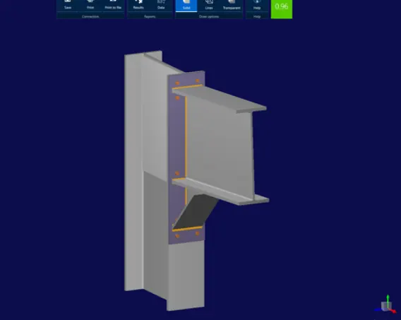
Support Side TAB
Size of Bolts: M_20 G8_8
BOLT COLUMN: 2
GAUGE OF BOULT = 140 MM
50 mm is the end distance.
54 millimeters is the edge distance.
HOLE TYPE: STANDARD ON SUPPORT
PLATE HOLE TYPE: STANDARD
TOP EXTENSION OF BOLT GROUP
MEASUREMENT OF 35 MM FROM BEAM FLANGE TO OUTER BOLT ROW
GROUP TOP FLANGE BOLT
BOLT ROWS: 1
MEASUREMENT OF 60 MM FROM BEAM FLANGE TO INNER BOLT ROW
BOTTOM FLANGE OF BOLT GROUP
BOLT ROWS: 1
MEASUREMENT OF 60 MM FROM BEAM FLANGE TO INNER BOLT ROW
TOP EXTENSION OF BOLT GROUP
Intragroup Bolt Group Hunk
BOLT ROWS: 1
60 MM DEPENDENCE BETWEEN HAUNCH FLANGE AND INNER BOLT ROW
HUNCH FOR BOLT GROUP EXTENSION
MEASUREMENT OF 40 MM FROM HAUNCH FLANGE TO OUTER BOLT ROW
RESISTANTS
NONE for transverse stiffeners
Yes, the column web panel's zone separator
Type of Stiffener: Supplementary Web Pages
STATUS: BOTH SIDE
THICKNESS: 10 MM
FLUSH: NADA
EXTENSION OF WEB PLATE: 75 MM
E250 A is the material.
ELECTRODE WELDING TO SUPPORT = E41
SIZE OF SUPPORT WELD: 6 MM
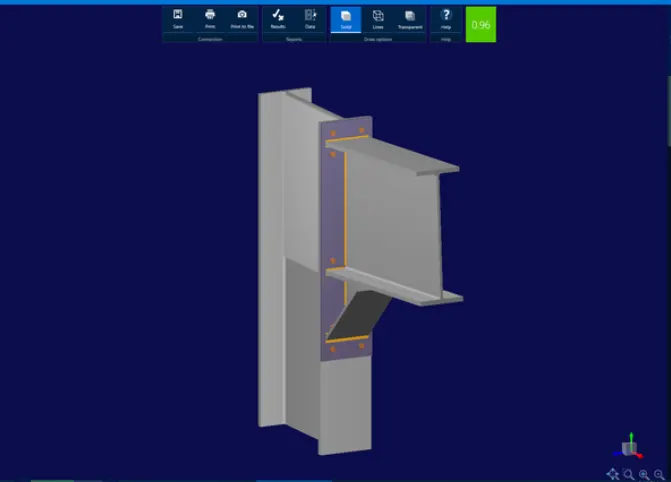
Result:
Conclusion 1: MOMENT END PLATE BCF HAUNCH CONNECTION BETWEEN BEAM AND COLUMN, OR THE UTILIZATION RATIO FOR CONNECTION DESIGN 1 = 0.96
Under an 85 percent utilization ratio, the stad model's beam and column utilization is safe.
The first conclusion is that the moment-end plate BCF halnch connection between the beam and the column has a utilization ratio of 0.96 for connection design 1.
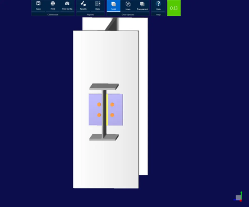
Conclusion 2: END PLATE BEAM COLUMN FLANGE BETWEEN BEAM AND COLUMN = 0.13 is the utilization ratio for connection design 2.
CONCLUSION 3: BOLTED SPLICE FLANGE PLATE COLUMN SPLICE'S UTILIZATION RATIO IS 0.95 FOR CONNECTION DESIGN 3.
Conclusion 4: THE UTILIZATION RATIO OF BOLTED SPLICE, FLANGE PLATE, BEAM SPLICE CONNECTION DESIGN 4 = 0.83
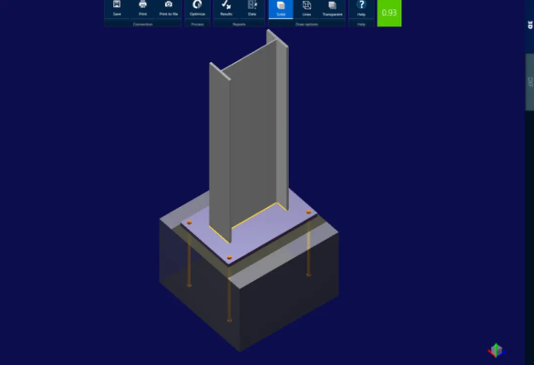
CONCLUSION 5: THE BASE PLATE UTILIZATION RATIO OF CONNECTION DESIGN 5 IS 0.93