Project-1: Powertrain for aircraft in runways
Part A:
1. Search and list out the total weight of various types of aircrafts.
2. Is there any difference between ground speed and air speed?
3. Why is it not recommended to use aircraft engine power to move it on the ground at Airport?
4. How an aircraft is pushed to runway when its ready to take off?
5. Learn about take off power, tyre design, rolling resistance, tyre pressure, brake forces when landing.
1)
- Airplanes can weigh anything from 1,500 pounds to over 800,0000 pounds.
- Light aircraft like the Cessna 172 have maximum weights of less than 4,000 pounds.
- Turboprops and private jets, like the Pilatus PC-12 and Gulfstream G650, have maximum weights between 10,450 and 99,600 pounds.
- Commercial airliners, such as the Boeing 737, Airbus A320, and Boeing 777-300ER, have maximum weights from 110,000 to 775,000 pounds.
- Heavy jets and cargo aircraft, like the Boeing 747 and Airbus A380, exceed maximum weights of 775,000 pounds.
Light Aircraft:
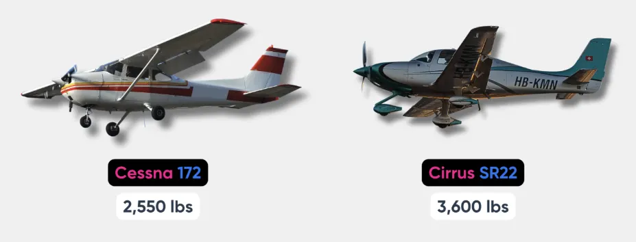
Light aircraft are often what come to mind when we talk about small, private airplanes. Typically, these aircraft are used for personal or small business purposes, carrying anywhere from one to six people.
Generally, light aircraft have a maximum takeoff weight (MTOW) of less than 12,500 pounds. But this figure includes the weight of the airplane, the fuel, passengers, and cargo it might carry.
Some examples include:
- The Cessna 172, is one of the most common light aircraft, with an MTOW of 1,550 pounds.
- The Diamond DA42, is a multi-engine light aircraft, with an MTOW of 4,407 pounds.
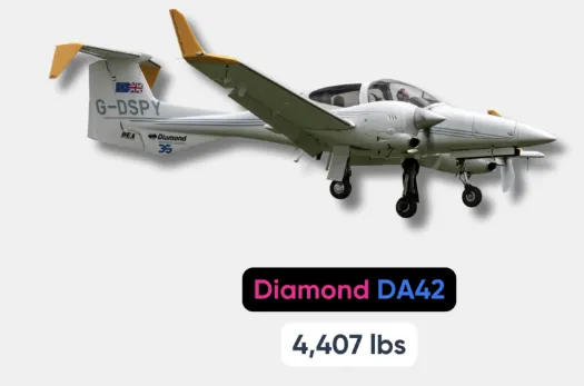
As you can see, even in this “light” category, weights can vary quite a bit depending on the specific model and configuration of the airplane.
Private Jets and Turboprops:

Turboprops typically have a maximum takeoff weight (MTOW) between 12,500 and 19,000 pounds.
On the lower end (and technically a light aircraft), the Pilatus PC-12, has a MTOW of 10,450 pounds. Turboprops combine the efficiency of propeller-driven aircraft with the speed and altitude capabilities of jets.
On the other hand, private jets come in light, mid-size, and heavy categories.
Light jets like the Embraer Phenom 300 have an MTOW of around 17,968 pounds.
Moving up, mid-size jets, such as the Hawker 800XP, have an MTOW of approximately 28,000 pounds.
Lastly, for those seeking ultimate luxury, heavy jets like the Gulfstream G650 have an astonishing MTOW of 99,600 pounds.
Commercial Airliners

Now we’re getting to the big leagues. Commercial airliners are the giants of the sky, ferrying hundreds of passengers across continents and oceans.
Commercial airliners have maximum takeoff weights ranging from approximately 110,000 pounds to over 775,000 pounds.
Commercial airliners can be broken down into two categories: narrow-body and wide-body.
In the narrow-body category, we have the Boeing 737 and Airbus A320.
The Boeing 737 has a maximum takeoff weight (MTOW) ranging from 129,000 pounds (64 tons) for the older 737-200 series to 203,000 pounds (101 tons) for the latest 737 MAX 10.
Meanwhile, the Airbus A320neo has a maximum takeoff weight of approximately 172,000 pounds.
These aircraft are perfect for short to medium-haul flights.
On the heavier side, wide-body airliners are designed for long-haul and ultra-long-haul flights. For instance, the Boeing 777-300ER, a popular wide-body aircraft, has a maximum takeoff weight of a whopping 775,000 pounds.
Heavy Jets

We’ve seen some impressive numbers so far, but now it’s time to look at the heaviest hitters in aviation – heavy jets and cargo aircraft. Designed for long-haul flights, these aircraft are engineered to carry substantial numbers of passengers or considerable amounts of freight.
Heavy jets have a maximum takeoff weight of over 775,000 pounds.
For instance, the Boeing 747, famously known as the “Queen of the Skies,” has a maximum takeoff weight (MTOW) of a staggering 970,000 pounds. This iconic airplane serves as a passenger airliner and prominent cargo aircraft in its Boeing 747-8 freighter variant, which can carry a similar MTOW.
Next, consider the Airbus A380, the world’s largest passenger airliner, with an MTOW of an astounding 1.2 million pounds. The ability to lift such a massive weight into the sky and keep it there for hours is nothing short of an engineering marvel!
In the realm of dedicated cargo aircraft, airplanes like the Lockheed C-5 Galaxy tip the scales even further. This gigantic military transport aircraft, one of the largest in the world, has an MTOW of an impressive 833,000 pounds.
Most of these aircraft are classified as “Super” heavy aircraft.
List of Airplane Weights
|
Aircraft |
Maximum Takeoff Weight (lbs) |
|
Piper PA-28-180 Cherokee |
2,400 |
|
Cessna 172S Skyhawk |
2,550 |
|
Cirrus SR22 |
3,600 |
|
Diamond DA42 Twin Star |
4,407 |
|
Pilatus PC-12 |
10,450 |
|
Beechcraft King Air 250 |
12,500 |
|
Embraer Phenom 300 |
17,968 |
|
Pilatus PC-24 |
18,300 |
|
Hawker 800XP |
28,000 |
|
Gulfstream G650 |
99,600 |
|
Boeing 737-200 |
129,000 |
|
Airbus A220-100 |
134,000 |
|
Airbus A320neo |
172,000 |
|
Boeing 737 MAX 10 |
203,000 |
|
Airbus A350-1000 |
679,000 |
|
Boeing 777-300ER |
775,000 |
|
Lockheed C-5 Galaxy |
833,000 |
|
Boeing 747-8I |
988,000 |
|
Airbus A380 |
1,208,000 |
2)
Yes, there is a significant difference between ground speed and airspeed. These terms are used in aviation and refer to the speed of an aircraft in different reference frames:
- Airspeed:
- Definition: Airspeed is the speed of an aircraft relative to the air mass through which it is flying.
- Measurement: It is measured using an airspeed indicator and is typically expressed in knots (nautical miles per hour) or sometimes in miles per hour (mph) or kilometers per hour (km/h).
- Factors Affecting Airspeed: Airspeed is affected by factors such as wind. There are two main types of airspeed:
- Indicated Airspeed (IAS): The speed shown on the airspeed indicator inside the cockpit.
- True Airspeed (TAS): The actual speed of the aircraft through the air, corrected for altitude and nonstandard temperature.
- Ground Speed:
- Definition: Ground speed is the horizontal speed of an aircraft relative to the Earth's surface.
- Measurement: It is typically measured using a GPS (Global Positioning System) or other ground-based tracking systems and is expressed in knots, mph, or km/h.
- Factors Affecting Ground Speed: Ground speed takes into account the aircraft's airspeed and the effects of wind. Therefore, ground speed can vary depending on whether the aircraft is flying into a headwind or with a tailwind.
In summary, airspeed is the speed of the aircraft through the air, while ground speed is the speed of the aircraft over the ground. The difference between them is primarily influenced by the wind conditions. If an aircraft has a headwind, the ground speed will be lower than the airspeed, and if it has a tailwind, the ground speed will be higher than the airspeed. Pilots use both airspeed and ground speed information to navigate and manage their flights effectively.
3)
Using aircraft engine power to move an aircraft on the ground at the airport is generally not recommended for several reasons:
Safety Concerns:
- Aircraft engines are powerful and designed for flight, not ground movement. Using engine power for ground movement can pose safety risks, especially in crowded airport environments where there are personnel, equipment, and other aircraft in close proximity.
Limited Maneuverability:
- Aircraft engines are optimized for thrust in the forward direction, not for precise ground maneuvering. Using engine power for ground movement can result in limited control and reduced maneuverability, increasing the risk of collisions or accidents.
Risk of FOD (Foreign Object Debris):
- Taxiing under engine power can increase the risk of ingesting foreign objects into the engine intake, leading to FOD damage. This is particularly true on taxiways and ramps where debris such as rocks, dirt, or loose items may be present.
Fuel Efficiency:
- Taxiing under engine power consumes fuel, and aircraft engines are generally less fuel-efficient at low speeds on the ground than during flight. Airlines and operators strive to minimize unnecessary fuel consumption to reduce operating costs and environmental impact.
Wear and Tear on Engines:
- Continuous use of engines for ground movement can contribute to wear and tear on the engines and other associated components. Aircraft engines are designed for take-off, climb, cruise, and descent phases, and using them extensively for ground taxiing can lead to additional maintenance requirements.
Noise Pollution:
- Aircraft engines are loud, and taxiing with engine power can contribute to noise pollution, especially in airport areas close to residential or sensitive zones. Many airports have regulations in place to manage and mitigate aircraft noise.
To address these concerns, airports and airlines use auxiliary power units (APUs) or ground tugs to move aircraft on the ground. APUs are smaller engines onboard the aircraft designed to provide electrical power and sometimes hydraulic power when the main engines are not running. Ground tugs are specialized vehicles that can push or pull aircraft on the ground safely and efficiently.
Using these alternatives helps ensure the safety of ground operations, minimizes fuel consumption, reduces engine wear, and helps manage environmental impact and noise levels in and around airports.
4)
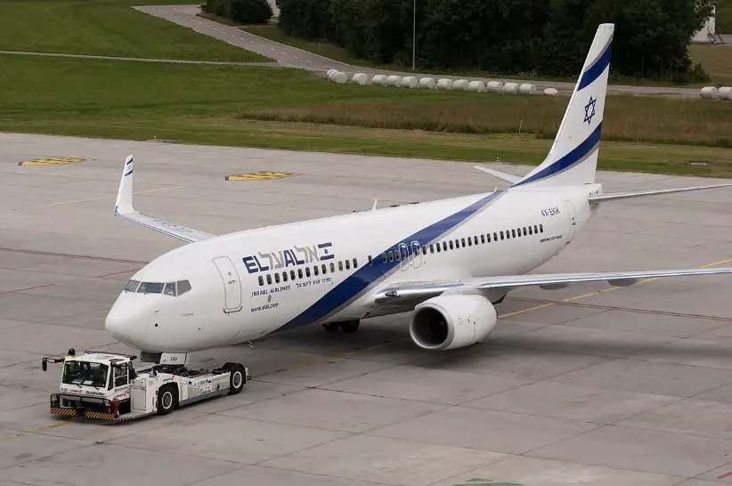
Aircraft are typically pushed back from the gate or parking position and guided to the runway for takeoff using specialized vehicles called pushback tugs. Here is an overview of the process:
Pushback Preparation:
Before pushback, ground personnel communicate with the flight crew to coordinate the pushback procedure. The pilots provide instructions on when to start the pushback and the direction in which they need to be pushed.
Pushback Tug Connection:
A pushback tug, a specialized vehicle with a towbar, is positioned in front of the aircraft. The towbar is connected to the aircraft's nose landing gear.
Cockpit Communication:
The ground crew communicates with the pilots in the cockpit, usually using hand signals or radio communication, to ensure that everyone is ready for the pushback.
Pushback Procedure:
The pushback tug then applies gradual force to move the aircraft away from the gate or parking stand. The tug is controlled by a trained operator who follows the instructions provided by the ground crew.
Guidance:
Ground crew members, often equipped with handheld radios or signaling devices, guide the pushback process to ensure the aircraft is pushed back safely and accurately.
Engine Start:
Once the aircraft is clear of the gate area, the pilots start the aircraft's engines. This is often done after the pushback to avoid jet blast affecting nearby structures or other aircraft.
Taxiing to the Runway:
After pushback is complete and the engines are running, the aircraft taxis to the assigned runway using its own power. Pilots follow taxiway markings and air traffic control instructions.
Pre-Takeoff Checks:
Before reaching the runway, the flight crew performs final pre-takeoff checks, including setting the flaps, verifying systems, and receiving takeoff clearance from air traffic control.
Takeoff:
Once the aircraft reaches the runway, the pilots apply takeoff thrust, and the aircraft accelerates for takeoff.
The use of pushback tugs is a standard procedure at airports for both safety and operational reasons. It allows for precise positioning of the aircraft, ensures that the engines are started away from the terminal building, and allows for efficient use of limited gate space at busy airports. The entire process is coordinated between ground crews, tug operators, and the flight crew to ensure a smooth and safe departure.
5)
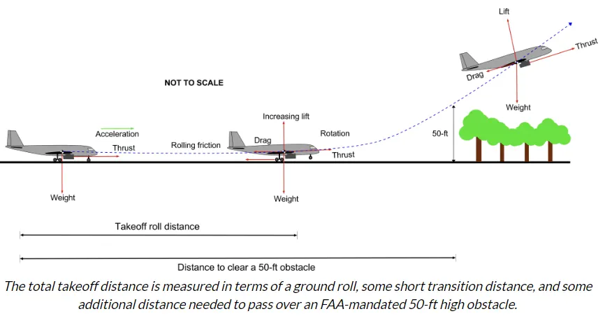
1. Takeoff Power:
- Definition: Takeoff power refers to the level of engine power set by the pilot during the takeoff roll to achieve the necessary thrust for the aircraft to become airborne.
- Factors Influencing Takeoff Power:
- Aircraft Weight: Heavier aircraft may require more takeoff power.
- Runway Length: Shorter runways may necessitate higher takeoff power.
- Environmental Conditions: Temperature, altitude, and wind affect engine performance.
2. Tyre Design:
- Purpose: Aircraft tires are designed to support the weight of the aircraft, provide a smooth ride, and withstand the forces experienced during takeoff, landing, and taxiing.
- Features:
- High-strength materials to handle heavy loads and high speeds.
- Tread patterns designed for optimal traction on various surfaces.
- Reinforcements to resist wear, abrasion, and heat.
3. Rolling Resistance:
- Definition: Rolling resistance is the force that opposes the motion of the aircraft as it rolls along the runway.
- Factors Influencing Rolling Resistance:
- Tire Design: Tread patterns and tire composition affect rolling resistance.
- Surface Condition: Runway surface condition, including smoothness and type of material.
- Tire Pressure: Proper tire inflation is crucial for minimizing rolling resistance.
4. Tire Pressure:
- Importance: Correct tire pressure is critical for safe and efficient aircraft operations.
- Effects of Incorrect Tire Pressure:
- Underinflation can lead to increased rolling resistance, heat buildup, and tire damage.
- Overinflation may result in reduced traction, a harsher ride, and increased wear on the tread.
5. Brake Forces When Landing:
- Braking System:
- Aircraft are equipped with hydraulic brake systems that apply pressure to the wheel brakes for deceleration during landing.
- Anti-skid systems help prevent wheel lockup and improve braking efficiency.
- Factors Influencing Brake Forces:
- Aircraft Weight: Heavier aircraft require greater brake force for deceleration.
- Runway Conditions: Wet or slippery runways may increase braking distances.
- Pilot Technique: Smooth application of brakes by the pilot influences deceleration.
- Heat Management:
- Intense braking during landing generates heat. Aircraft are equipped with systems, such as brake cooling fans, to dissipate heat and prevent overheating.
- Tire Wear:
- The landing phase can exert significant forces on the tires. Pilots aim to apply brakes smoothly to minimize wear and maximize tire life.
Understanding and managing these factors are crucial for safe and efficient aircraft operations. Pilots, maintenance personnel, and engineers work together to ensure that aircraft tires are properly maintained, pressures are within specified limits, and braking systems are functioning optimally. Regular inspections and adherence to operational guidelines contribute to the overall safety and performance of the aircraft.
6)
For this question, the Towing vehicle considered is KAMBLAR Tow tractor TBL 190 and the aircraft considered is Airbus A319
TBL 190 is designed for pushback and maintenance towing of aircraft from MD-80/A319 up to B777/A340.
Length: 8,100 mm
Width: 3,450 mm
Height: 2,050 mm
Thus, frontal area is calculated to be: 7.07m2
Dry weight: 15,150 kg
Working speed: 23 km/h, 30 km/h (14.3 mph)
The Airbus A319 has the following specifications:
Length 33.8m
Wingspan 35.8m
Height 11.8m
Maximum take-off weight 64,000 – 75,500 kg
Weight of Aircraft 35,400 kg
Drag Coefficients (Cd): Taxing: 0.031
Take-off: 0.024
Landing: 0.017
The frontal area for the Airbus A319 can estimated as
Area = (Width)*(Height)
= (2*2.54)*(2*2.38)
= 24.18m2
The area of the wings can be estimated to be
Area = Width*Height
(35.08-(2*2.54))*(0.3)
=30.72*0.3
=9.2118m2
Hence, the total frontal area to be considered for the aircraft and tow truck will be
=Frontal Area of tow truck + Frontal Area of Aircraft
= Frontal Area of tow truck + (Frontal Area of Wings + Frontal Area of cabin)
= 7.07 + 9.2118 + 24.18
=40.46m2
The forces to be taken into consideration while calculating the traction power required are
- Frr = μrr mg
Where, Frr is the Rolling Resistance Force in N
μrr is the Coefficient of Rolling Resistance
m is the total mass of vehicle in kg
g (g=9.81) is the acceleration due to gravity in m/s2
- Fad =
Where, Fad is the Aerodynamic Drag Force in N
is the Air Density
A is the Frontal Area of vehicle in m2
Cd is the Drag Coefficient
V2 is the velocity in m/s
- Fh = mg sin(Ψ)
Where, Fh is the Hill Climbing Force in N
Ψ is the Hill Climbing Angle in radian
- Fa = ma
Where a is the acceleration of the vehicle in m/s2
The summation of all the forces multiplied by the vehicle velocity will give the required power.
The torque required can also be calculated if the wheel radius and gear ratio of the towing vehicle are known by using the formula
Torque = Force*radius/Gear Ratio
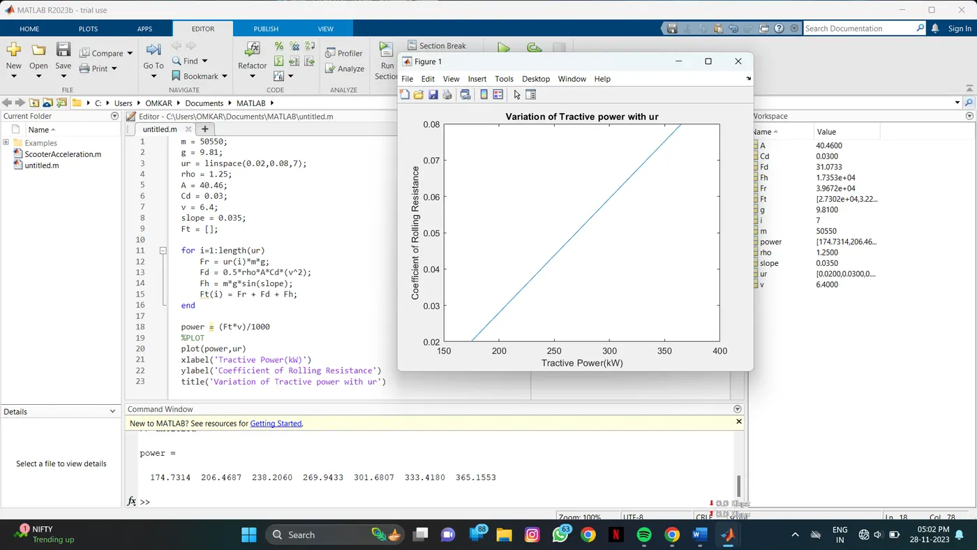
For calculating the required power. The acceleration force is neglected here. Tractive power requirement with changing μrr is plotted
7)
The power calculated in the above example is 174.73 kW for the rolling resistance coefficient of 0.02. The same is considered for the further calculation.
Since 1kWh = 1.34HP
174.73kW will be equivalent to approximately 235HP. Hence, the motor should have a rating of 235 HP
The Vascat 175kW (235HP) x 3200RPM/6000RPM AC Vector Motor IP23 B3 160X might be suitable.
Energy required for towing = Power * Time
= 174.73kW * 10min
= 29.12 kWh
Thus, the battery for the towing vehicle should be able to supply a minimum of 30kWh of energy for one successful towing cycle of 10mins. The C-Rate for the battery should be very high. The Nissan Leaf uses a battery of 30kWh but the discharge rate is significantly lower than what will be required for this application.
The typical powertrain block diagram for the aircraft towing vehicle will be as shown below. The battery will store DC power and the On-board Charger will convert the AC supply into a DC supply so that the battery can be charged. Further, due to ease to control the speed and torque, an AC Induction motor (IM) with vector control is used. Thus the DC power stored in the battery has to be converted into AC power by use of an Inverter circuit arrangement as shown in the figure.
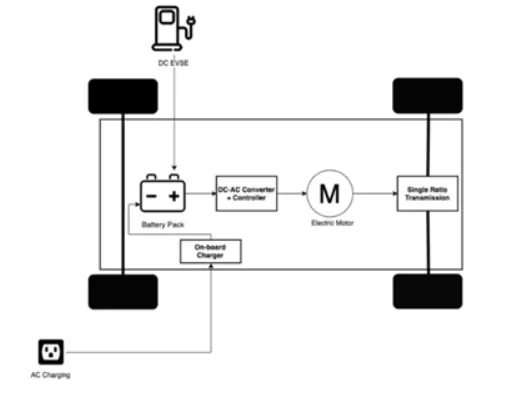
Block diagram of powertrain:
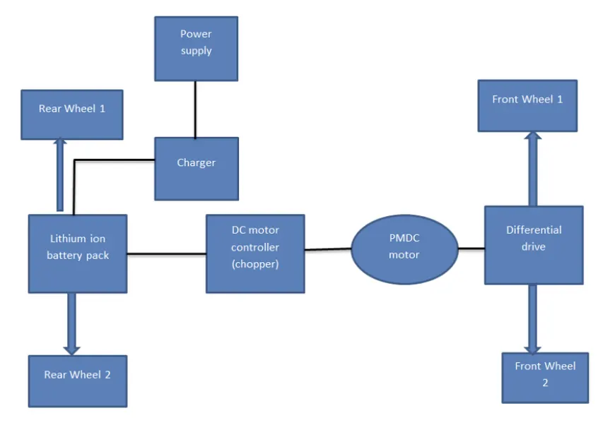
Simulink Model:
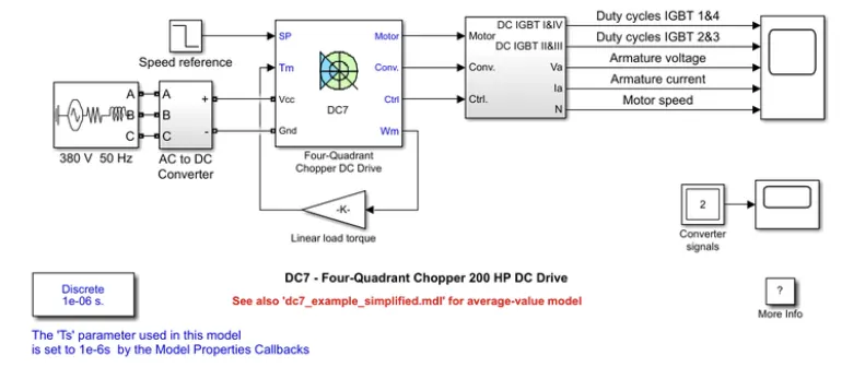
The above figure shows that powertrain arrengement of tow tractor for towing aircraft. The battery source is displayed at the left. The battery parameters are the maximum voltage value of selected motor. The motor characteristics is implementedas calculated above.
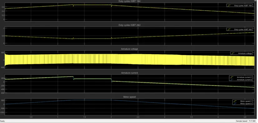
The 200 HP DC motor is separately excited with a constant 150 V DC field voltage source. The armature voltage is provided by an IGBT converter controlled by two PI regulators.
The converter is fed by a 515 V DC bus obtained by rectification of a 380 V AC 50 Hz voltage source. In order to limit the DC bus voltage during dynamic braking mode, a braking chopper has been added between the diode rectifier and the DC7 block.
The first regulator is a speed regulator, followed by a current regulator. The speed regulator outputs the armature current reference (in p.u.) used by the current controller in order to obtain the electromagnetic torque needed to reach the desired speed.
The speed reference change rate follows acceleration and deceleration ramps in order to avoid sudden reference changes that could cause armature over-current and destabilize the system.
The current regulator controls the armature current by computing the appropriate duty ratios of the 5 kHz pulses of the four IGBT devices (Pulse Width Modulation).
For proper system behaviour, the instantaneous pulse values of IGBT devices 1 and 4 are opposite to those of IGBT devices 2 and 3. This generates the average armature voltage needed to obtain the desired armature current.
In order to limit the amplitude of the current oscillations, a smoothing inductance is placed in series with the armature circuit.