Project-1: Powertrain for aircraft in runways
1) The aircraft gross weight (also known as the all-up weight and abbreviated AUW) is the total aircraft weight at any moment during the flight or ground operation. An aircraft's gross weight will decrease during a flight due to fuel and oil consumption. An aircraft's gross weight may also vary during a flight due to payload dropping. At the moment of releasing its brakes, the gross weight of an aircraft is equal to its takeoff weight. During flight, an aircraft's gross weight is referred to as the en-route weight or in-flight weight.
Total weight of various types of aircrafts is as follows:
Glider - Glider is a fixed wing plane that is supported in flight by the dynamic reaction of the air against its lifting surfaces, and whose free weight does not depend on an engine. Most gliders do not have an engine, although motor glider have small engines for extending their flight when necessary by sustaining the altitude (normally a sailplane is on a continuously descending slope) with some being powerful enough to take off self launch.
Weight of Glider : 110 kg - 200 kg
Powered Lift - A powered lift aircraft takes off vertically under engine power but uses a fixed wing for horizontal flight. These aircraft do not need a long runway to take off and land, like helicopters, but they have a speed and performance similar to standard fixed wing aircraft in combat or other situations.
Weight of powered lift planes : 160 kgs
Fighter Aircraft - A fighter aircraft, often referred to simply as a fighter, is a military fixed wing aircraft designed primarily for air to air combat against other aircraft. The key performance features of a fighter include not only its firepower but also its high speed and manuverability relative to the target aircraft.
Weight of fighter Aircraft : 13500 kgs
Military Transport Planes - Military transport aircraft or military cargo aircraft are used to airlift troops, weapons and other military equipment to support military operations. Transport aircraft can be used for both strategic and tactical missions, and are often diverted to civil emergency relief missions.
Weight of military transport planes : 250,000 kgs
Aerobatic Planes - An aerobatic aircraft is an aerodyne (a heavier-than-air aircraft) used in aerobatics, both for flight exhibitions and aerobatic competitions.
Weight of Aerobatic planes : 771 kgs
2) Difference between ground speed and air speed is as follows:
True airspeed is simply the speed at which an aircraft is moving relative to the air it is flying in. As such, it’s also the speed at which the air is flowing around the aircraft’s wings.
Ground speed, on the other hand, is the aircraft’s speed relative to the ground. One thing that should be noted here is that it’s its horizontal rather than vertical speed – an aircraft climbing completely vertically would have a ground speed of zero.
In other words, while airspeed is what determines whether there is enough airflow around an aircraft to make it fly, ground speed is what determines how fast an aircraft will get to its destination.
3) It is not recommended to use aircraft engine power to move it on the ground at Airport because of the following reasons:
- Generally most of the airplane can move itself in reverse manner by making use of reverse thrust technology.But in most of the practical it is not possible because when airplanes start using reverse thrust it will consume lot of fuels as well as causes lot of noise and also hazardous for the people working near by. When an aircraft's engine is activated, the thrust can create a high-speed wind that can easily cause damage to the airport terminal, surrounding ground vehicles, jetway, baggage and most importantly, ground personnel.
- To solve this kind of issue we use a towing vehicle which helps to tow the vehicle in reverse dierection and it eill be tugged until it reaches a safe place and from there onwards airplane will move by itself for further take off.
4) In aviation, pushback is an airport procedure during which an aircraft is pushed backward away from its parking position, usually at an airport gate by an external power. Pushbacks are carried out by special, low-profile vehicles called pushback tractors or tugs. Although many aircraft are capable of moving themselves backward on the ground using reverse thrust (a procedure referred to as a powerback), the resulting jet blast or prop wash would cause increased noise, damage to the terminal building or equipment, and hurt airport staff due to high-speed debris. This debris would also be sucked into the engine, as it is in normal use, and cause excessive wear - a major cause of wear on aircraft engines is during ground use. A pushback is therefore the preferred method when ground-handling aircraft.
Pushbacks at busy aerodromes are usually subject to ground control clearance to facilitate ground movement on taxiways. Once clearance is obtained, the pilot will communicate with the tractor driver (or a ground handler walking alongside the aircraft in some cases) to start the pushback. To communicate, a headset may be connected near the nose gear. Since the pilots cannot see what is behind the aircraft, steering is done by the pushback tractor driver and not by the pilots. Depending on the aircraft type and airline procedure, a bypass pin may be temporarily installed into the nose gear to disconnect it from the aircraft's normal steering mechanism.
Once the pushback is completed, the towbar is disconnected, and any bypass pin is removed. The ground handler will show the bypass pin to the pilots to make it clear that it has been removed. The pushback is then complete, and the aircraft can taxi forward under its own power.
5) Take off power:
Takeoff is the phase of flight in which an aerospace vehicle leaves the ground and becomes airborne. For aircraft traveling vertically, this is known as liftoff. For aircraft that take off horizontally, this usually involves starting with a transition from moving along the ground on a runway. For light aircraft, usually full power is used during takeoff. Large transport category (airliner) aircraft may use a reduced power for takeoff, where less than full power is applied in order to prolong engine life, reduce maintenance costs and reduce noise emissions. In some emergency cases, the power used can then be increased to increase the aircraft's performance. Before takeoff, the engines, particularly piston engines, are routinely run up at high power to check for engine-related problems.
Tyre design:
An aircraft tyre is designed to withstand extremely heavy loads while landing, take off, taxing, and parking. The number of wheels required for aircraft increases with the weight of the aircraft, as the weight of the aeroplane needs to be distributed more evenly. Engineers are challenged with designing tires with cool running, heat-resistant materials while simultaneously exceeding tire service requirements.An aircraft tyre is constructed for the purpose it serves.
- They support the weight of an aircraft while it is on the ground.
- It also provides the necessary traction for braking and stopping of an aeroplane.
- Tyre also helps to absorb the shock of landing and provide cushioning the roughness of takeoff, roll-out, and taxi operations.
Two types of tires are used in aircraft applications — bias-ply tires and radial tires.
Rolling Resistance:
In addition to the familiar forces like thrust, weight, lift, drag there is a rolling resistance force caused by friction between tyre and ground. When aircraft is towing or taxiing to push it into the runway or when takeoff roll is happening, the rolling resistance force act against the traction force of the aircraft. This rolling resistance force depends on many factors like surface of the road, roughness of the road, dry or wet condition of the road, tyre pressure, tyre material, tyre temperature, thread pattern of the tyre etc, which determines the rolling resistance force.
Tyre Pressure:
Aircraft tyres are designed to withstand heavy loads and shocks durong landing and take off and also needs to distribute weight evenly. Tyre pressure varies from plane to plane.
- The tires do not use the typical compressed air we would use from a fuel station supply or a home air compressor.
- Aviation tires are made of a much stronger compound than what we use for the auto industry and in fact, they use nitrogen gas to inflate the tires, as opposed to compressed air.
- This provides additional strength to the tires in general, to support the tremendous weight they carry moving the plane or on take-off and for landing.
- The average pressure they run in the tires is between 200-220 PSI, it again depends on the model aircraft(Automobile run 30-40 PSI on average).
- Tires are required to replace after every 300 or so cycles. A cycle represents 1 for a landing and 1 for a lift-off. Every time a plane lands and departs, this is considered 2 cycles.
- When the tire pressure becomes too low then values of rolling resistance increase too much.
Brake forces when landing:
When a plane is about to land, it is at high speed. Friction is produced with the ground, and it loses kinetic energy, and hence, the vehicle stops. But the thing about friction is that it depends entirely on the weight of the vehicle. In the case of the airplane, when it is landing, the aerodynamic lift renders the weight of the plane zero, and hence, the brakes on the wheels are pretty much inefficient to stop the plane. That is why the plane needs to find other ways to stop until both the aerodynamic lift and the speed has reached a sufficient stage. Modern aircraft use several different braking systems to do this:
Wing Spoilers:
Many airplanes use wing spoilers to assist with braking when landing. Not to be confused with ailerons, spoilers are extendable flaps on the ends of an airplane’s wings. Pilots can raise the spoilers to decelerate the airplane as it approaches the runway. And even while on the runway, pilots will typically leave the wing spoilers raised. Raised wing spoilers create the drag, which essentially slows down the airplane so that it’s able to brake more quickly.
Aircraft Disc Brakes:
In addition to wing spoilers, airplanes use disc brakes. Airplane disc brakes are similar to the braking system in automobiles. They consist of a pair of calipers that, when engaged, squeeze pads against the rotors of an airplane’s landing gear. Disc brakes are designed to remain static at all times. In other words, they don’t rotate with the wheels of an airplane’s landing gear. As the wheels turn, the disc brakes will remain static and stationary. They are a vital component of an airplane’s braking system because they are designed to apply pressure to the airplane’s wheels. Disc brakes will squeeze the wheels, thereby slowing down the speed at which they spin. In turn, this reduces the speed of the airplane so that it can come to a complete stop on the runway.
Reverse Thrust:
Many jet airplanes use reverse thrust to assist with braking during landings. Reverse thrust is a feature in jet engine airplanes that, as the name suggests, involves the reversal of the engines’ thrust. When flying, the thrust is projected out the rear of an airplane’s engines. When landing, however, pilots may use the reverse thrust feature. Reverse thrust changes the direction of the engines’ thrust. Rather than projecting out the rear, the thrust will be projected out the front. This reversal of thrust provides deceleration that allows airplanes to slow down more quickly when landing.
6) To calculate the force and power required to push / pull an aircraft by a towing vehicle the following has been considered:
Towing vehicle:
The Douglas Tugmaster type TBL- 280 Mk4 towbarless aircraft handling tractor is considered for pushback, inter-gate towing, and longer distance maintenance towing operations at higher speeds. The following factors have been considered
- Maximum cradle lifting capacity = 35,000 kgs(Aircraft nose wheel weight).
- Length (Excluding Coupler) = 333” (8,470 mm) = 8.47m
- Width = 134” (3,400 mm) = 3.4m
- Wheel Base = 173” (4,400 mm) = 4.4m
- Height = 79" (2,000 mm) = 2m
- Tyre Size = R 22.5 = 571.5mm = 0.5715m
- Maximum Governed Speed = 20 mph (32 kph)
The coefficient of friction depends on the objects that are causing friction. The value is usually between 0 and 1 but can be greater than 1. A value of 0 means there is no friction at all between the objects. A value of 1 means the frictional force is equal to the normal force. It is a misconception that the coefficient of friction is limited to values between 0 and 1. A coefficient of friction that is more than 1 just means that the frictional force is stronger than the normal force.
Coefficient of rolling resistance (μrr) = 0.02 (Truck tyre in asphalt concrete road)
Aircraft model:
Airbus A310 aircraft model has been considered as pushback operation.
- Standard or Higher Gross Weight = 164000 kg
- Height = 15.80 m
- Width = 43.90 m
- Drag Coefficent (Cd) = 0.02685
The total force and power required to push/pull an aircraft by the towing vehicle.
Formula used:
Total Force (F) = Frr+Fad
Rolling resistance Force (Frr) = μrr.m.g
Drag Force (Fad) = (1/2).ρ.A.Cd.v^2
To find rolling resistance force:
For Aircraft :
Rolling resistance force (Frr) = μrr.m1.g
Where,
μrr = Coefficient of rolling resistance of aircraft = 0.02
m1 = mass of the aircraft = 164000 kg
g = gravitational force = 9.8 m/s^2
Frr1 = 0.02 x 164000 x 9.81
= 32176.80 N
For Towing Vehicle:
Rolling resistance force (Frr2) = μrr.m2.g
Where,
μrr = Coefficient of rolling resistance of towing vehicle = 0.02
m2 = mass of the towing vehicle = 35000 kg
g = gravitational force = 9.8 m/s^2
Frr2 = 0.02 x 35000 x 9.81
= 6909 N
So the total Rolling resistance force
Frr = Frr1+Frr2
= 32176.80 + 6909
= 39085.80 N
To find Air drag force,
For Aircraft :
Air Drag Force (Fad1) = (1/2)⋅ρ⋅A1⋅Cd1⋅v^2
Where,
ρ = density of air = 1.25 kg/m^3
A1 = Height of the airbus x Width of the airbus
= 15.80 x 43.90 = 693.62 m^2
Assume that vehicle running at the speed of 20 kmph.
v = (20 x 5/18)
= 5.56 m/s
Cd1 = Drag Coefficient of aircraft = 0.02685
Fad1 = (1/2)x 1.25 x 693.62 x 0.0265 x (5.56)^2
= 355.137 N
For Towing Vehicle:
Air Drag Force (Fad2) = ρ.A2.Cd2.v^2
Where,
ρ = 1.25 kg/m^3
A2 = Height of the towing vehicle x Width of the towing vehicle
= 2 x 3.4 = 6.8 m^2
Assume that vehicle running at the speed of 20 kmph.
v = (20 x (5/18)
= 5.56 m/s
Cd2 = Drag Coefficient of the towing vehice = 0.6
Fad2 = (1/2) x 1.25 x 6.8 x 0.6 x (5.56)^2
= 78.82 N
So the total Air Drag Force
Fad = Fad1 + Fad2
= 355.137 + 78.82
= 437.13 N
Now, the total force (F) =
the Rolling resistance force (Frr) + the Air Drag Force (Fad)
= 39085.80 + 437.13
= 39522.93 N
Power required to push/pull the aircraft:
Power = Total Force x velocity
= 39522.93 x 5.56
= 219747.49 W
Therefore, Power = 219.74 kW
Simulation model for the above power calculation is as follows:
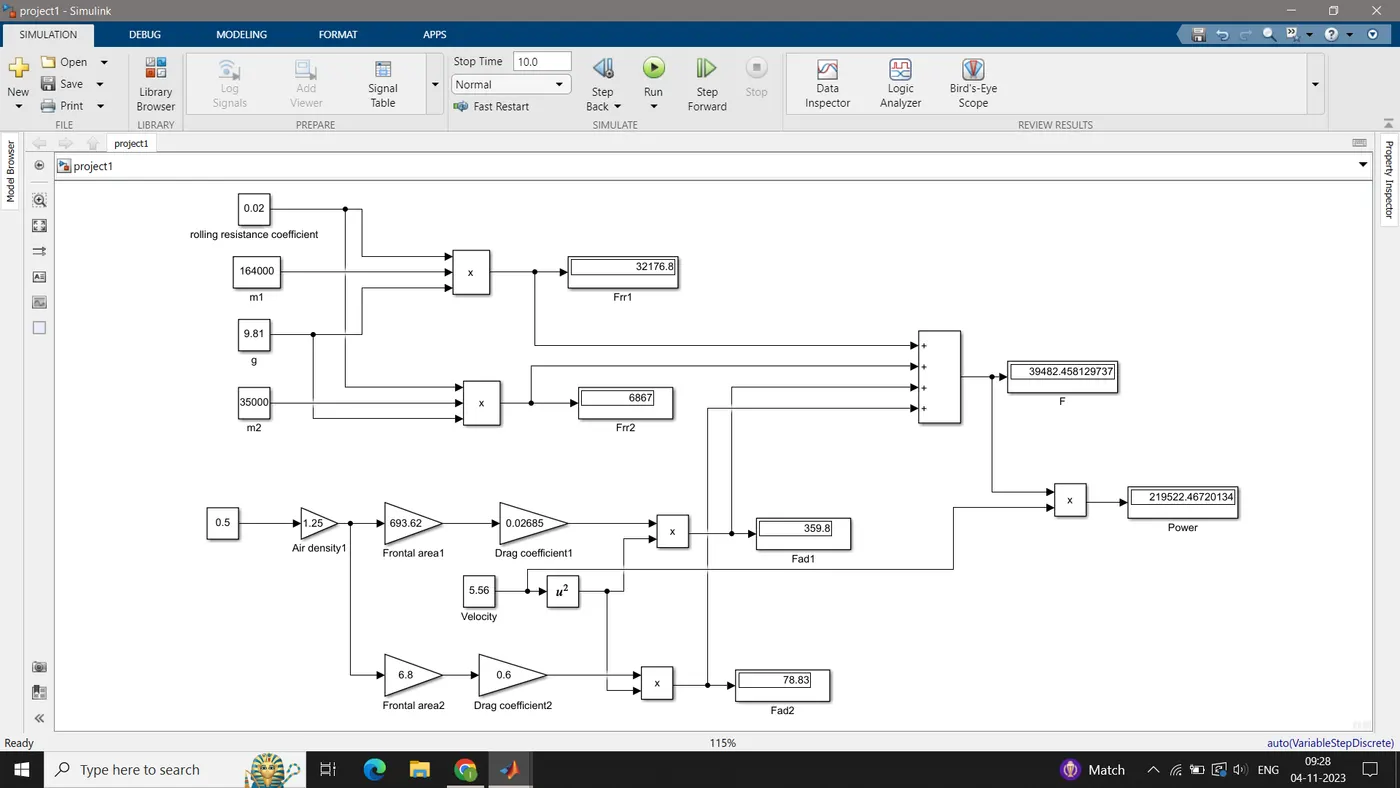
- Constant and gain blocks are used to feed the parameters such as mass, coefficient, and the other parameters.
- By using product block the resistive forces are calculated.
- By using the sum block the total forces are calculated.
- Lastly, the outputs are visualized by using display blocks.
7) From the above question the power required to push / pull an aircraft by a towing vehicle is obtained as 219.74 kW. Hence the energy required for the vehicle is calculated as:
Energy = Power x t
Where,
t = time taken for towing vehicle
Here, we consider the time taken for towing vehicle as about 20 minutes.
E = 219.74 x (1200/3600)
E = 73.24 kWh
The above data shows how much power is taken at the speed of 20 kmph and how much energy is consumed in 20 minutes of time. In this case, we have to find out the input power to drive the duty cycle of the towing vehicle.
The formula for duty cycle is given below,
Duty cycle = Power input/Power output
We know that,
Power = Voltage x Current
Here we consider,
Input Voltage supply (Motor Specification) = 400 V
Input Current Value = 620 A
Battery Nominal Voltage = 400 V
Battery capacity = Energy / Battery nominal voltage
= (73.24*1000) / (400)
= 183.1 Ah
Now substitute the voltage and current value in the power formula to get the input power data,
Power input = 400 x 620 = 248000 W
By converting the unit of power from W to kW we get,
Power input = 248 kW
Therefore we have obtained power input and power output now substitute these values in the duty cycle formula we get,
Duty cycle = Power output/Power input
= 219.74/248
= 0.886
So, The duty cycle for the towing vehicle considered is 88.6%. This duty is obtained for our system based upon several assumptions.
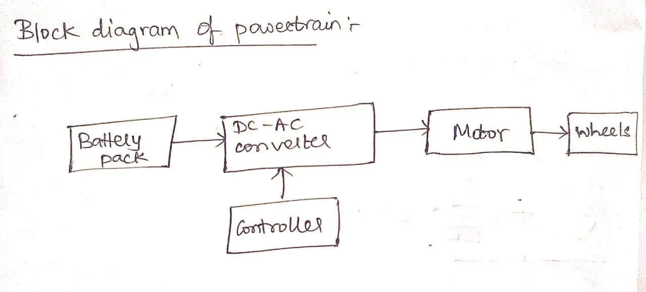
Block diagram:
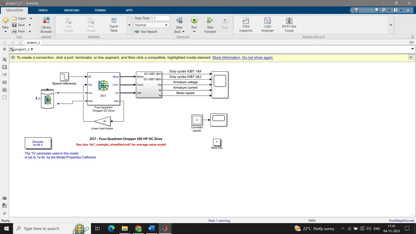
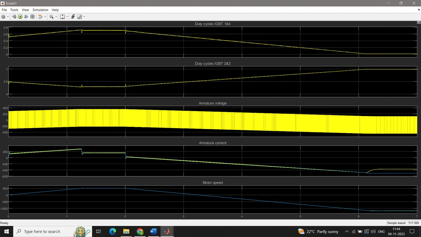
The simulink model developed ()for the above calculation is as follows: