Project-1: Powertrain for aircraft in runways
ANSWER:
AIM:-
1. Search and list out the total weight of various types of aircrafts.
2. Is there any difference between ground speed and air speed?
3. Why is it not recommended to use aircraft engine power to move it on the ground at Airport?
4. How an aircraft is pushed to runway when its ready to take off?
5. Learn about take off power, tyre design, rolling resistance, tyre pressure, brake forces when landing.
6. A. With necessary assumptions, calculate the force and power required to push / pull an aircraft by a towing vehicle.
B. Develop the model for the calculated force and power using Simulink.
7. A. Design an electric powertrain with type of motor, it’s power rating, and energy requirement to fulfill aircraft towing application in Simulink. Estimate the duty cycle range to control the aircraft speed from zero to highest. Make all required assumptions. Prepare a table of assumed parameters. Draw block diagram of powertrain.
(Hint :DC7 Block)
B. Also, Design the parameters in excel sheet.
1. Total weight of various types of aircrafts:-
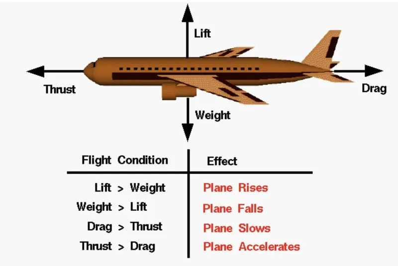
Weight is a major factor in airplane construction and operation, and it demands respect from all pilots and particular diligence by all maintenance personnel. Excessive weight reduces the efficiency of an aircraft and the available safety margin if an emergency condition should arise. The total weight is the maximum take-off weight. It is the maximum mass at which the aircraft is certified for take-off due to structural or other limits.
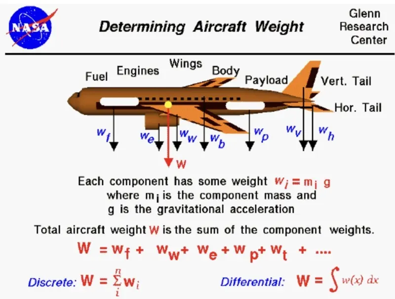
we know that ,weight is the force generated by the gravitional attraction of the earth which we can estimate by the given formula w=m*g, where w=is the weight, m is the mass, g is the gravitational constants g=9.8m/sec^2 or 32.2ft/sec^2 . In case of a whole aircraft there are different parts and each part of the aircraft bears a unique weight and mass example : the wings, the engines, the payload, and the fuel.The mass of the individual components can be calculated if we know the size of the components and its chemical composition example: iron, plastic, aluminium, gasoline etc.
the total weight of the aircraft is the sum of the individual components given as: W=w(Fuselage)+w(Payload)+w(Engines)+w(Wings)+....
We can see from the figure:-
Aircraft authorised gross weight is defined as the total aircraft weight at any moment during the flight or ground operation. The authorised weight limits that can be legally be used by any operator or airline are listed in the AFM and the weight and balance manual. They are also referred as purchased weights.
The different terms represent different weights or masses. For each flight, the weights are taken into account for several reasons.
The classification of different types of weight under gross weight can be made in the following categories:
Manufacturer’s Empty Weight (MEW):
It is the weight of the aircraft “as built” and includes the weight of the structure, power plant furnishings, installations, systems and other equipment that are considered an integral part of an aircraft.
Zero Fuel Weight (ZFW):
This is the total weight of the airplane and all its contents including unusable fuel but excluding the total weight of the usable fuel on board. As a flight progresses and fuel is consumed, the total weight of the airplane reduces, but the ZFW remains constant.
Operational Empty Weight (OEM):
It is the basic weight of an aircraft including the crew, all fluids necessary for operation, all operator items and equipment required for flight but excluding usable fuel and the payload.
Maximum Zero Fuel Weight (MZFW):
Maximum zero fuel weight is the maximum weight allowed before usable fuel and other specified usable agents are loaded.
MZFW=OEM / DOW + Payload
Maximum Taxi Weight (MTW) or Maximum Ramp Weight (MRW):
It is the maximum permitted weight of the aircraft at which it may be moved on the ground either with its own engine or towed by a tractor. It can also be defined as maximum weight for ground maneuvering including the weight of run-up and taxi fuel.
MRW= MZFE + Ramp Fuel
Maximum Take-Off Weight (MTOW):
It is the maximum permitted weight at the start of the take-off. While determining this limit, the manufacturer takes into consideration the strength of the material used for the manufacturing of the aircraft and standard performance variables such as runway temperature, altitude, atmospheric pressure, wind components, flaps, etc.
MTOW=MZFW + Take-Off Fuel
Regulated Take-Off Weight (RTOW):
As told in the above definition depending on different factors (e.g. flap setting, altitude, air temperature, length of runway), RTOW or maximum permissible takeoff weight varies for each takeoff. It can never be higher than MTOW.
Maximum Landing Weight (MLW):
When aircraft touches the ground it puts force of the runway as well as on the tyres and under carriage, so to ensure structural safety of the aircraft MLW is taken into consideration. Manufactures have calculate this force to be approximately “9” times the weight of the aircraft. Thus when the aircraft has to make an emergency landing or when the weight of the aircraft before landing exceeds the MLW defined by the manufacturer the pilots dump fuel to reduce the weight of the aircraft.
MLW= MTOW – Trip Fuel
Aircrafts's empty weight:
The aircraft weight with fuel left in tank +engine oil +other operating fluids
Payload:
The fuel weight+ passengers weight +other operating fluids.
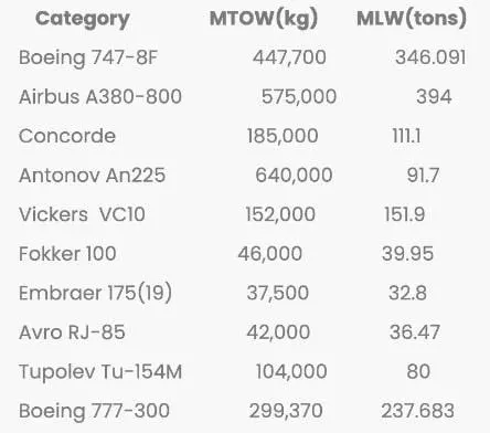
Different Air craft and respective weight are given under:
2. Is there any difference between ground speed and air speed?
First we need to understand about the Wind speed. True airspeed is simply the speed at which an aircraft is moving relative to the air it is flying in. As such, it’s also the speed at which the air is flowing around the aircraft’s wings. Airplanes always try to take off and land into the wind. This requires a lower ground speed, which means the plane can take off or land in the shortest distance travelled along the ground. Since runways have a fixed length, you want to get airborne as fast as possible on take-off and stopped as soon as possible on landing.
It is important to understand the relationships of wind speed to ground speed and airspeed.
Wind speed:
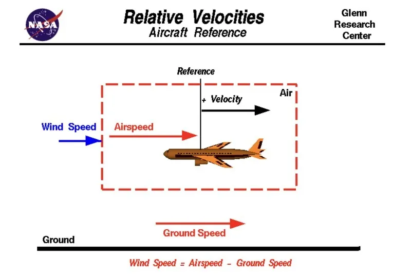
For a reference point picked on the ground, the air moves relative to the reference point at the wind speed. Notice that the wind speed is a vector quantity and has both a magnitude and a direction. Direction is important. A 20 mph wind from the west is different from a 20 mph wind from the east. The wind has component in all three primary directions, In this figure, we are considering only velocities along the aircraft's flight path. A positive velocity is defined to be in the direction of the aircraft's motion. We are neglecting cross wind, which occur perpendicular to the flight path but parallel to the ground, and updraft and downdraft which occur perpendicular to the ground.
Air speed:
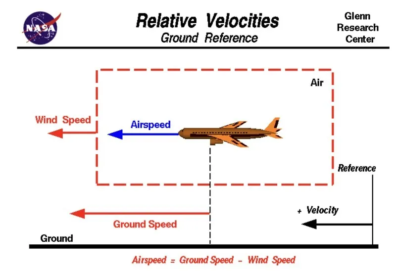
The relative velocity between the object and the air is called air speed. Airspeed cannot be directly measured from a ground position, but must be computed from the ground speed and the wind speed. Airspeed is the vector difference between the ground speed and the wind speed.
Ground speed:
It is the horizontal speed of an aircraft relative to the ground. An aircraft heading vertically would have a ground speed of zero. Ground speed can be determined by the vector sum of the aircraft's true airspeed and the wind speed and the direction of motion.
On a perfectly still day, the airspeed is equal to the ground speed. But if the wind is blowing in the same direction that the aircraft is moving, the airspeed will be less than the ground speed.
3. Why is it not recommended to use aircraft engine power to move it on the ground at Airport?
Boeing commercial airplanes are equipped with engines rated from 18,000 to nearly 100,000 lb of thrust. Such thrust levels provide for safe takeoff, flight, and landing over a wide range of temperatures, altitudes, gross weights, and payload conditions. However, the exhaust wake from these engines can pose hazards in commercial airport environments. Operators and airport authorities must carefully consider these hazards and the resulting potential for injury to people and damage to or caused by baggage carts, service vehicles, airport infrastructure, and other airplanes.
The reason are;
There is a risk of injury to ground support personnel who may be in relatively close to the air-craft.
It is easier for the truck driver to see the surroundings better than the pilot who is sitting in the cock-pit wit limiting window. the pushback driver knows the airport better than the pilot.
Effectively a loss of control can happen, especially during high power engine running. Damage can occur to the air-craft itself,other aircraft nearby and other buildings.
A new system was proposed where a new system in which a push-back truck will move the air-craft all the way to run-way to save fuel and reduce impact of environment.
The plane engines are very loud, when more than one plane will addup their sound, then it will be unbearable for passengers and other parts near airport.
Despite the power and potentially destructive nature of the jet blast, there are relatively few jet blast incidents. Due to the invisible nature of the jet blast and the aerodynamic properties of light aircraft, light aircraft moving about airports are particularly unsafe. Pilots of light aircraft frequently stay off to the side of the runway, rather than follow in the center, to negate the effect of the blast. Towing with Taxibot saves precious fuel and reduces engine wear and tear. The ignition will be turned only when the aircraft reaches the runway. The usage of Taxibots will significantly bring down the consumption of fuel by as much as 85 percent used during taxiing of an aircraft. Taxi boats will also help in decongesting boarding gates and the apron area by providing efficient pushbacks.
So, due to the noise and fumes plus they burn a lot of fuel aircrafts are towed into a spot due to it being a small parking space for safety.
4. How an aircraft is pushed to runway when its ready to take off?
In aviation, pushback is an airport procedure during which an aircraftis pushed backwards away from an airport gate by external power. Pushbacks are carried out by special, low-profile vehicles called pushback tractors or tugs.
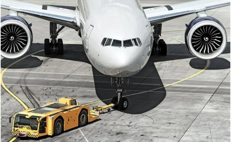
Pushback is when an aircraft is pushed backwards away from the airport gate by vehicles called tugs or tractors. Closer to departure, an aircraft tug will park right in front of the nose wheel. The tug might be directly attached to the plane's nose gear with a tow bar, or could be a "wheel-lift" tug. These tugs cradle the nose gear, then lift it up before moving the plane. That gives the tug driver control over the plane's direction during pushback. New taxi technologies are appearing, like pilot-controlled tugs, and electric motors mounted to the plane's landing gear. Both promise to save fuel, and reduce airport noise.
TAXIING :
It is defined as the movement of the air-craft on the ground, under its own power where as towing or pushback is where the air-craft is moved by the tug. The air-craft usually moves on wheels but the term also used for the air-craft that has skies or floating equipments. An airplane uses taxiways to taxi from one-place on the air-port to another, example when the air-craft moves from hanger to the runaway
TOWING :
Movement of large aircraft about the airport, flight line, and hangar is usually accomplished by towing with a tow tractor (sometimes called a “tug”). In the case of small aircraft, some moving is accomplished by hand pushing on the correct areas of the aircraft. Aircraft may also be taxied about the flight line but usually only by certain qualified personnel.
Towing aircraft can be a hazardous operation, causing damage to the aircraft and injury to personnel, if done recklessly or carelessly. However, specific instructions for each model of aircraft are detailed in the manufacturer’s maintenance instructions and are to be followed in all instances.When towing the aircraft, the towing vehicle speed must be reasonable, and all persons involved in the operation must be alert. When the aircraft is stopped, do not rely upon the brakes of the towing vehicle alone to stop the aircraft. The person in the flight deck must coordinate the use of the aircraft brakes with those of the towing vehicle.
5. Learn about take off power, tyre design, rolling resistance, tyre pressure, brake forces when landing.
Take off Power:
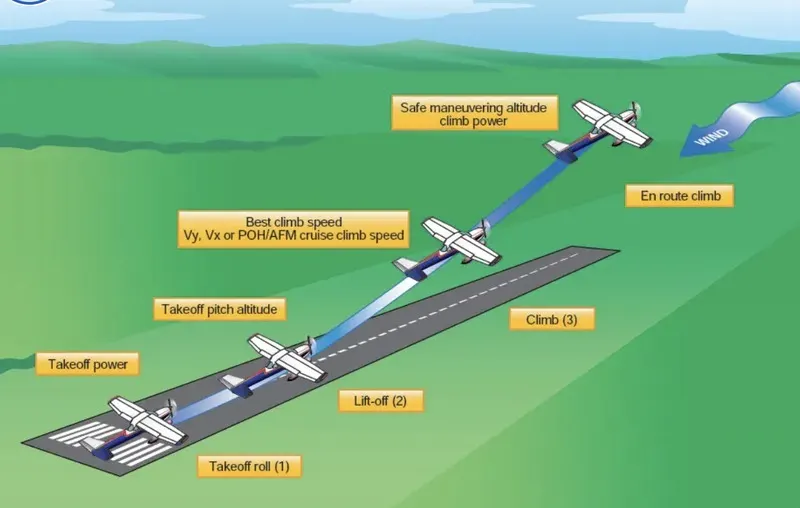
Take off is the phase of the flight in which an aeroplane leaves ground and becomes airbone.For lighter aircraft full power is given durong take off where as on the other hand large cargo carriers aircraft make use of less power during take off inorder to inrease the life span of engine,reduce maintenance cost ,reduce engine heat and also for a smooth take off flight.
In the physics realm Power"> = Mass x Acceleration x distance/time
To many it means "how much throttle" , which is how much fuel/time.
"Throttle" x prop efficiency = Thrust">
This gives you a unit of Force that can be directly compared to glide data as follows:
Potential energy Mass x Gravity x altitude loss = Thrust"> x horizontal distance flown
This rearranged to Thrust"> = Mass x Gravity x altitude loss/horizontal distance flown
Thrust"> = force required for straight and level flight, expressed in "pounds or Newtons"
Tyre design:
An aircraft tyre are deisgned to withstand extreme heavy loads by absording shocks during and there by providing cushioning effect.The tire design of an aircraft may seem a challenging job, because the tyre has to withstand heavy loads while landing, take-off, taxiing and parking. The number of wheels required for an aircraft increases as the weight of the aircraft increases cause it should be distributed evenly. The tyre generates a lot of heat during landing because it drags the wheel to match its momentum. The tyre is designed in such away that it withstands hugh crosswind conditions, extreme pressure and to prevent hydroplanning and for increased braking effect.
Aircraft tyre may be of tube type or tube less type:
Tubeless tyres are more advantageous over tube-type. There is no longer the use of tube-type tyre in recent aviation. Nowadays all airliners are using tubeless tyres. Tubeless that are meant to be used without a tube has the word TUBELESS on the sidewall of the tyre.
Aircraft tyre may be of radial or bias:
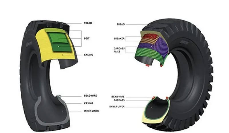
* Radial tyre: It has fiber strands of the poly fabric at 90degree to the direction of rotation and the tyre side-wall. This restricts flexibility of the bi-deirectional sidewall while it strengthnes the tyre to carry heavy loads . Due to their unique construction radial tyres are resistant to penetration and cuts. Due to stiffer threads they distribute weight evenly. Thus provide greater traction and helps in preventing heat.
* Bias tyre: It has the fabric bias oriented with and cross the direction of rotation and the side-wall. Since the fabric stretches, the tire is flexible and can absorb loads, the cut resistnt area is the sidewalls, strength is obtained by adding piles, these tyres doesn't absorb heat well.
Rolling resistance:
It is defined as the force resisting the motion when a body rolls on a surface (ex- ball, tyre) .Rolling resistance can be seen in an aircraft when the air-craft takes off from the runway and while landing on the runway.
Rolling resistance force can be written as: Frr=Urr*m*g(N)
Where Urr= coefficient of rolling resistant
m= Mass(kg)
Frr= rolling resistance
g= acceleration due to gravity(9.81m/s^2)
Tyre pressure:
Aircraft tires are usually inflated with nitrogen to minimize expansion and contraction from extreme changes in ambient temperature and pressure experienced during flight. Dry nitrogen expands at the same rate as other dry atmospheric gases (normal air is about 80% nitrogen), but common compressed air sources may contain moisture, which increases the expansion rate with temperature.
Tests of airliner aircraft tires have shown that they are able to sustain pressures of maximum 800 psi (55 bar; 5,500 kPa) before bursting. During the tests the tires have to be filled with water, to prevent the test room being blown apart by the energy that would be released by a gas when the tire bursts.
The main landing gear on the Concorde was typically inflated to 232 psi (16.0 bar), whilst its tail bumper gear tires were as high as 294 psi (20.3 bar). The high pressure and weight load on the Concorde tyres were a significant factor in the loss of Air France flight 4590
Brake forces when landing:
Brakes provide this critical stopping function during landings to enable airplanes to stop within the length of the runway. They also stop aircraft during rejected takeoff events, in which an attempted takeoff is canceled as the airplane is rolling down the runway before it lifts off from the ground due to engine failure, tire blowout, other system failure or direction from air traffic control.
Braking an aircraft is a challenging job for most of the pilots especially during landing in a rainy and cross wind environment.
Inorder to encounter this kinds of problem pilots usually make use of spoilers and reverse thust method inorder to have a safe landing so that the energy required to apply brakes on tires can be reduced and henceforth they do not skid.
Now there is method which determines the brake force for aircrafts and they are as follows:
K=1/2 mv^2
where m= mass of aircraft and v=velocity of aircraft.
There are three kinds of braking forces that can be employed in the aircraft to decelerate it in the run way.
* Engine power:
The most important action to achieve deceleration from a speed at which the engines are still producing forward motion is to select all thrust/power levers to the ground idle position promptly, and if available, continue the action through to the selection of reverse thrust or reverse propeller pitch. Thrust reversers and reverse propeller pitch are most effective at high speeds.
* Wheel brakes:
To be effective, braking action at any speed depends upon sufficient friction existing between the tires and the runway surface achieved through freely rotating wheels.
* Mechanical spoilers:
The mechanical deflection of parts of the wing upper surfaces and tail cone assembly can assist deceleration in two ways:
6. A. With necessary assumptions, calculate the force and power required to push / pull an aircraft by a towing vehicle.
B. Develop the model for the calculated force and power using Simulink.
A.The rolling resistance for the air plane can be calculated as
Fr = c mr ag
where
Fr = rolling resistance
c = rolling resistance coefficient
mr = rolling mass (kg)
ag = acceleration of gravity (9.81 m/s2)
Here we consider the mass of a plane is 40000 kg and the rolling resistance co-efficient between the aircraft wheel and the runway is 0.02
The force required to overcome the rolling resistance can be calculated as
Fr = 0.02 * (40000 kg) *(9.81 m/s2)
= 7848 N
The friction for the puller can be calculated to
Ff = μ W
= μ mf ag
Where
Ff = frictional force 👎
μ = friction coefficient
W = Weight 👎
mf = friction mass (kg)
Ff =Fr
The friction coefficient between a pulling truck rubber wheels and dry runway is 0.9.
mf = (7848 ) / (0.9 (9.81 m/s2))
= 889 kg
Taking radius of the wheel R as 0.3m
The torque is given by
T=F*R
T= 7848 * 0.3
= 2354.4 Nm
The power for pulling/push the aircraft can be calculated as
P=F*V
Velocity of pull vehicle taken as 1.388 m/s
V=1.388 m/s
P=7848*1.388
=10893.02 W
=10.89 kW
B. Develop the model for the calculated force and power using Simulink.
The following are the equations modeled in simulink
Frr=mgμrr
Fad=1/2*ρACdv^2
Fte=mgμrr+1/2*ρACdv^2
power(p) =force *velocity
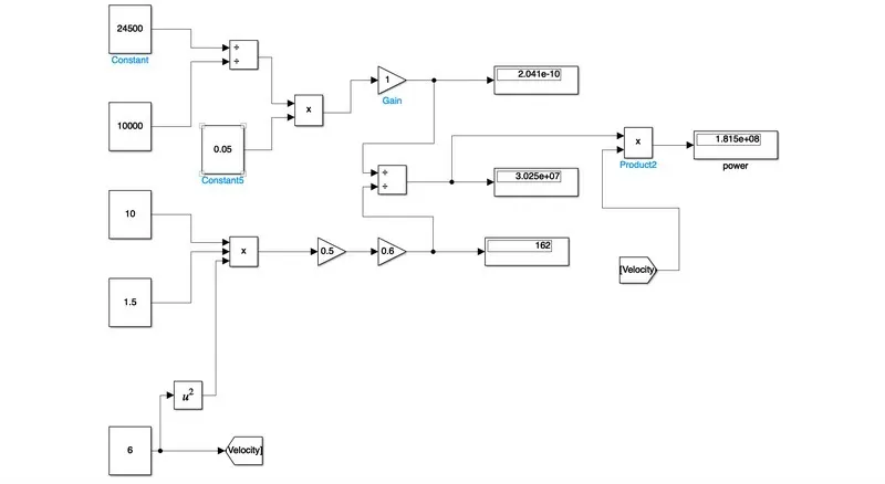
Assumed parameters are given to the model using Constant blocks.
Using add and multiply blocks, the formulae for rolling resistance force and Aerodynamic drag are calculated.
Using Add block, the overall force is determined.
By mulitplying force with velocity, power is calculated.
The values of force and power are displayed using Display block.
7. A. Design an electric powertrain with type of motor, it’s power rating, and energy requirement to fulfill aircraft towing application in Simulink. Estimate the duty cycle range to control the aircraft speed from zero to highest. Make all required assumptions. Prepare a table of assumed parameters. Draw block diagram of powertrain.
Taking the prevoius example power value 10 kW for this problem
Power =10 kW
The energy required can be calculated as
E=P*t
assuming taxi time of 5 mins.
E=10*(5*60) kJ
= 3000kJ
From power equation
Vo*Io=ηVi*Ii
where,
Vo is the output voltage
Io is the output current
η is the power efficiency (ranging from 0 to 1)
Vi is the input voltage
Ii is the input current
Consider DC input voltage as 48V and Power as 12kW
P= Vi*Ii
12000=48*Ii
Ii=250A
The efficiency is calculated as
η=10000/12000
=0.83
From the above power equation:
Vo*Io=ηVi*Ii
Vo*250=0.83*48*250
Vo=40V
The Vout =Vin/1-D
40=48/(1-D)
D= 0.2 the duty cycle has in the range of (0,0.2)
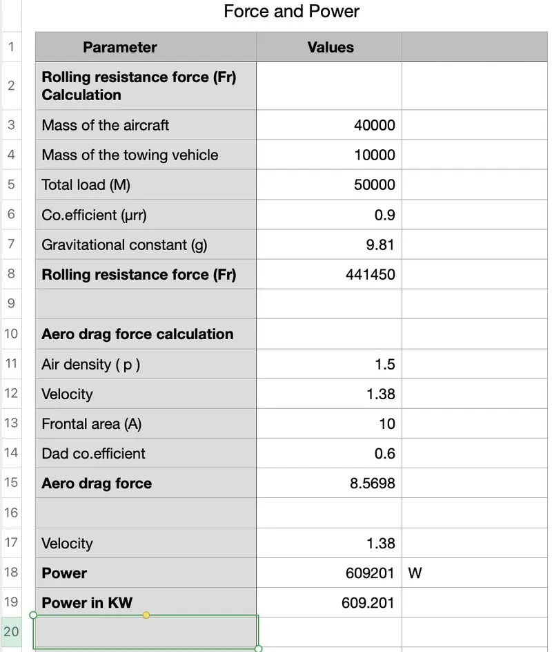
mass of the aircraft (ma) -40000kg
mass of the towing vehicle -10000kg
rolling resistance(μrr) -0.02
air density(ρ) -1.5kg/m^3
frontal area (A)- 10m^2
aero drag coefficient(Cd)- 0.9
gravitational constant(g)- 9.81
velocity(v) -21.6km/hr=6m/sec
B. Design the parameters in excel sheet.
Reference:
https://www.grc.nasa.gov/www/k-12/airplane/Animation/airrel/anrelw.html
https://www.boeing.com/commercial/aeromagazine/aero_06/textonly/s02txt.html
https://www.aviationhunt.com/aircraft-tyre-construction/
https://studentlesson.com/powertrain-and-drivetrain-definition-diagram-components-working/