Project-1: Powertrain for aircraft in runways
OBJECTIVE PART A:
1. Search and list out the total weight of various types of aircrafts.
2. Is there any difference between ground speed and air speed?
3. Why is it not recommended to use aircraft engine power to move it on the ground at Airport?
4. How an aircraft is pushed to runway when its ready to take off?
5. Learn about take off power, tyre design, rolling resistance, tyre pressure, brake forces when landing.
OBJECTIVE PART B:
6. A. With necessary assumptions, calculate the force and power required to push / pull an aircraft by a towing vehicle.
B. Develop the model for the calculated force and power using Simulink.
7. A. Design an electric powertrain with type of motor, it’s power rating, and energy requirement to fulfill aircraft towing application in Simulink. Estimate the duty cycle range to control the aircraft speed from zero to highest. Make all required assumptions. Prepare a table of assumed parameters. Draw a block diagram of powertrain.
(Hint :DC7 Block)
B. Also, Design the parameters in excel sheet.
:-
1. Search and list out the total weight of various types of aircrafts.
ANS:
TOW = Maximum take-off weight, MLW = Maximum landing weight, TOR = Take-off run (SL, ISA+15°, MTOW), LR = Landing run (SL, ISA+15°, MLW)
| Type | MTOW [kg] | MLW [tonnes] | TOR [m] | LR [m] | ICAO category | FAA category |
|---|---|---|---|---|---|---|
| Antonov An-225 | 640,000 | 591.7 | 3,500 | Heavy | Super | |
| Scaled Composites Model 351 Stratolaunch | 589,670 | 3,660 | Heavy | Super | ||
| Airbus A380-800[1][2][3] | 575,000 | 394 | 3,100 | 1,930 | Heavy | Super |
| Boeing 747-8F | 447,700 | 346.091 | 3,100 | 1,800 | Heavy | Heavy |
| Boeing 747-8 | 443,613 | 306.175 | 3,100 | Heavy | Heavy | |
| Boeing 747-400ER | 412,770 | 295.742 | 3,090 | Heavy | Heavy | |
| Antonov An-124-100M | 405,060 | 330 | 2,520 | 900 | Heavy | Heavy |
| Boeing 747-400 | 396,900 | 295.742 | 3,018 | 2,179 | Heavy | Heavy |
| Lockheed C-5 Galaxy[4][5][6] | 381,000 | 288.417 | 2,530 | 1,494 | Heavy | Heavy |
| Boeing 747-200[7] | 377,840 | 285.7 | 3,338 | 2,109 | Heavy | Heavy |
| Boeing 747-300[7] | 377,840 | 260.32 | 3,222 | 1,905 | Heavy | Heavy |
| Airbus A340-500[8] | 371,950 | 240 | 3,050 | 2,010 | Heavy | Heavy |
| Airbus A340-600[8] | 367,400 | 256 | 3,100 | 2,100 | Heavy | Heavy |
| Boeing 777F | 347,800 | 260.816 | 2,830 | Heavy | Heavy | |
| Boeing 777-300ER | 351,800 | 251.29 | 3,100 | Heavy | Heavy | |
| Boeing 777-200LR | 347,450 | 223.168 | 3,000 | Heavy | Heavy | |
| Boeing 747-100[7] | 340,200 | 265.3 | Heavy | Heavy | ||
| Airbus A350-1000 | 308,000 | 233.5 | Heavy | Heavy | ||
| Boeing 777-300 | 299,370 | 237.683 | 3,380 | Heavy | Heavy | |
| Boeing 777-200ER | 297,550 | 213 | 3,380 | 1,550 | Heavy | Heavy |
| Airbus A340-300[8][9] | 276,700 | 190 | 3000 | 1926 | Heavy | Heavy |
| McDonnell Douglas MD-11 | 273,300 | 185 | 2,990 | 1,890 | Heavy | Heavy |
| Airbus A350-900 | 270,000 | 175 | 2,670 | 1,860 | Heavy | Heavy |
| Ilyushin Il-96M | 270,000 | 195.04 | 3,115 | 2,118 | Heavy | Heavy |
| McDonnell Douglas DC-10 | 256,280 | 183 | 2,990 | 1,890 | Heavy | Heavy |
| Boeing 787-9[10] | 254,000 | 192.777 | 2,900 | Heavy | Heavy | |
| Boeing 787-10[10] | 254,000 | 201.849 | Heavy | Heavy | ||
| Airbus A340-200[8][11] | 253,500 | 181 | 2990 | Heavy | Heavy | |
| Airbus A330-900 | 251,000 | 191 | 3,100 | Heavy | Heavy | |
| Ilyushin IL-96-300 | 250,000 | 175 | 2,600 | 1,980 | Heavy | Heavy |
| Airbus A330-300[12][13] | 242,000 | 185 | 2500 | 1750 | Heavy | Heavy |
| Airbus A330-200[12][13] | 242,000 | 180 | 2,220 | 1,750 | Heavy | Heavy |
| Lockheed L-1011-500 | 231,300 | 166.92 | 2,636 | Heavy | Heavy | |
| Boeing 787-8[10] | 228,000 | 172.365 | 3,300 | 1,695 | Heavy | Heavy |
| Lockheed L-1011-200 | 211,400 | Heavy | Heavy | |||
| Ilyushin IL-86 | 208,000 | 175 | Heavy | Heavy | ||
| Boeing 767-400ER | 204,000 | 158.758 | 3,414 | Heavy | Heavy | |
| Airbus A300-600R[14] | 192,000 | 140 | 2,385 | 1,555 | Heavy | Heavy |
| Boeing 767-300ER | 187,000 | 136.08 | 2,713 | 1,676 | Heavy | Heavy |
| Concorde | 185,000 | 111.1 | 3,440 | 2,220 | Heavy | Heavy |
| Airbus A300-600[14] | 163,000 | 138 | 2,324 | 1,536 | Heavy | Heavy |
| Boeing 767-300 | 159,000 | 136.078 | 2,713 | 1,676 | Heavy | Heavy |
| Airbus A310-300[14] | 157,000 | 124 | 2,290 | 1,490 | Heavy | Heavy |
| Vickers VC10 | 152,000 | 151.9 | Heavy | Heavy | ||
| Boeing 707-320B[15] | 151,000 | 97.5 | Heavy | Heavy | ||
| Boeing 707-320C[15] | 151,000 | 112.1 | Heavy | Heavy | ||
| Douglas DC-8-61 | 147,000 | Heavy | Heavy | |||
| Airbus A310-200[14] | 142,000 | 123 | 1,860 | 1,480 | Heavy | Heavy |
| Airbus A400M | 141,000 | 122 | 980 | 770 | Heavy | Heavy |
| Douglas DC-8-32 | 140,000 | Heavy | Heavy | |||
| Douglas DC-8-51 | 125,000 | Medium | Large | |||
| Boeing 757-300 | 124,000 | 101.6 | 2,550 | 1,750 | Medium | Large |
| Boeing 707-120B[15] | 117,000 | 86.3 | Medium | Large | ||
| Boeing 757-200 | 116,000 | 89.9 | 2,347 | 1,555 | Medium | Large |
| Boeing 720B[16] | 106,000 | 79.5 | Medium | Large | ||
| Boeing 720[16] | 104,000 | 79.5 | Medium | Large | ||
| Tupolev Tu-154M | 104,000 | 80 | Medium | Large | ||
| Tupolev Tu-204SM | 104,000 | 87.5 | 2,250 | Medium | Large | |
| Convair 880 | 87,500 | Medium | Large | |||
| Boeing 737-900 | 85,000 | 66.36 | 2,500 | 1,704 | Medium | Large |
| Boeing 737-900ER | 85,000 | 71.35 | 2,804 | 1,829 | Medium | Large |
| Boeing 727-200 Advanced[17] | 84,000 | 70.1 | Medium | Large | ||
| Airbus A321-100[18] | 83,000 | 77.8 | 2,200 | 1,540 | Medium | Large |
| Boeing 737-800 | 79,000 | 65.32 | 2,308 | 1,634 | Medium | Large |
| Boeing 727-200[17] | 78,000 | 68.1 | Medium | Large | ||
| McDonnell-Douglas MD-83 | 73,000 | 63.28 | Medium | Large | ||
| Boeing 727-100[17] | 72,500 | 62.4 | Medium | Large | ||
| Boeing 727-100C[17] | 72,500 | 62.4 | Medium | Large | ||
| McDonnell-Douglas MD-90-30 | 71,000 | 64.41 | 2,165 | 1,520 | Medium | Large |
| de Havilland Comet 4 | 70,700 | Medium | Large | |||
| Boeing 737-700 | 70,000 | 58.06 | 1,921 | 1,415 | Medium | Large |
| Airbus A320-100[18] | 68,000 | 66 | 1,955 | 1,490 | Medium | Large |
| Boeing 737-400 | 68,000 | 54.9 | 2,540 | 1,540 | Medium | Large |
| de Havilland Comet 3 | 68,000 | Medium | Large | |||
| Boeing 377 | 67,000 | Medium | Large | |||
| Boeing 737-600 | 66,000 | 54.66 | 1,796 | 1,340 | Medium | Large |
| Airbus A220-300 | 65,000 | 57.61 | 1,890 | 1,494 | Medium | Large |
| Hawker Siddeley Trident 2E | 65,000 | Medium | Large | |||
| Airbus A319[18] | 64,000 | 62.5 | 1,850 | 1,470 | Medium | Large |
| Boeing 737-300 | 63,000 | 51.7 | 1,939 | 1,396 | Medium | Large |
| Boeing 737-500 | 60,000 | 49.9 | 1,832 | 1,360 | Medium | Large |
| Airbus A220-100 | 59,000 | 50.8 | 1,463 | 1,356 | Medium | Large |
| Airbus A318[18] | 59,000 | 57.5 | 1,375 | 1,340 | Medium | Large |
| Boeing 717-200HGW | 55,000 | 47.174 | 1,950 | Medium | Large | |
| Douglas DC-7 | 55,000 | Medium | Large | |||
| de Havilland Comet 2 | 54,000 | Medium | Large | |||
| Boeing 717-200BGW | 50,000 | 46.265 | 1,950 | Medium | Large | |
| de Havilland Comet 1 | 50,000 | Medium | Large | |||
| Douglas DC-6A | 48,600 | Medium | Large | |||
| Douglas DC-6B | 48,500 | Medium | Large | |||
| Embraer 190[19] | 48,000 | 43 | 2,056 | 1,323 | Medium | Large |
| Caravelle III | 46,000 | Medium | Large | |||
| Fokker 100 | 46,000 | 39.95 | 1,621 | 1,350 | Medium | Large |
| Douglas DC-6 | 44,000 | Medium | Large | |||
| Avro RJ-85 | 42,000 | 36.74 | Medium | Large | ||
| Handley Page Hermes | 39,000 | Medium | Large | |||
| Embraer 175[20] | 37,500 | 32.8 | 2,244 | 1,304 | Medium | Large |
| Bombardier CRJ900[21] | 36,500 | 33.345 | 1,778 | 1,596 | Medium | Large |
| Embraer 170[22] | 36,000 | 32.8 | 1,644 | 1,274 | Medium | Large |
| Bombardier CRJ700 | 33,000 | 30.39 | 1,564 | 1,478 | Medium | Large |
| Douglas DC-4 | 33,000 | Medium | Large | |||
| Vickers Viscount 800 | 30,400 | Medium | Large | |||
| Bombardier Q400 | 28,000 | 28.01 | 1,219 | 1,295 | Medium | Large |
| Bombardier CRJ200 | 23,000 | 21.319 | 1,918 | 1,479 | Medium | Large |
| ATR 72-600 | 22,800 | 22.35 | 1,333 | 914 | Medium | Large |
| Saab 2000 | 22,800 | 21.5 | 1,300 | Medium | Large | |
| Embraer ERJ 145 | 22,000 | 19.3 | 2,270 | 1,380 | Medium | Large |
| ATR 42-500 | 18,600 | 18.3 | 1,165 | 1,126 | Medium | Small |
| Saab 340 | 13,150 | 12.930 | 1,300 | 1,030 | Medium | Small |
| Embraer 120 Brasilia | 11,500 | 11.25 | 1,560 | 1,380 | Medium | Small |
| BAe Jetstream 41 | 10,890 | 10.57 | 1,493 | 826 | Medium | Small |
| Learjet 75[23] | 9,752 | 8.709 | 1,353 | 811 | Medium | Small |
| Pilatus PC-24[24] | 8,300 | 7.665 | 893 | 724 | Medium | Small |
| Embraer Phenom 300[25] | 8,150 | 7.65 | 956 | 677 | Medium | Small |
| Beechcraft 1900D | 7,765 | 7.605 | 1,036 | 853 | Medium | Small |
| Cessna Citation CJ4[26] | 7,761 | 7.103 | 1039 | 896 | Medium | Small |
| de Havilland Hercules | 7,000 | Medium | Small | |||
| Embraer Phenom 100 | 4,800 | 4.43 | 975 | 741 | Light | Small |
2. Is there any difference between Ground speed and Air Speed?
Ans:
e of the most confusing concepts for young scientists is the relative velocity between objects. Aerodynamic forces are generated by an object moving through a fluid (liquid or gas). A fixed object in a static fluid does not generate aerodynamic forces. Hot air balloons "lift" because of buoyancy forces and some aircraft like the Harrier use thrust to "lift" the vehicle, but these are not examples of aerodynamic lift. To generate lift, an object must move through the air, or air must move past the object. Aerodynamic lift depends on the square of the velocity between the object and the air. Now things get confusing because not only can the object be moved through the air, but the air itself can move. To properly define the relative velocity, it is necessary to pick a fixed reference point and measure velocities relative to the fixed point. In this slide, the reference point is fixed to the ground, but it could just as easily be fixed to the aircraft itself. It is important to understand the relationships of wind speed to ground speed and airspeed.
Wind Speed
For a reference point picked on the ground, the air moves relative to the reference point at the wind speed. Notice that the wind speed is a vector quantity and has both a magnitude and a direction. Direction is important. A 20 mph wind from the west is different from a 20 mph wind from the east. The wind has components in all three primary directions (north-south, east-west, and up-down). In this figure, we are considering only velocities along the aircraft's flight path. A positive velocity is defined to be in the direction of the aircraft's motion. We are neglecting cross winds, which occur perpendicular to the flight path but parallel to the ground, and updrafts and downdrafts, which occur perpendicular to the ground.
Ground Speed
For a reference point picked on the ground, the aircraft moves relative to the reference point at the ground speed. Ground speed is also a vector quantity so a comparison of the ground speed to the wind speed must be done according to rules for vector comparisons.
Airspeed
The important quantity in the generation of lift is the relative velocity between the object and the air, which is called the airspeed. Airspeed cannot be directly measured from a ground position, but must be computed from the ground speed and the wind speed. Airspeed is the vector difference between the ground speed and the wind speed.
Airspeed = Ground Speed - Wind Speed
On a perfectly still day, the airspeed is equal to the ground speed. But if the wind is blowing in the same direction that the aircraft is moving, the airspeed will be less than the ground speed.
Examples
Suppose we had an airplane that could take off on a windless day at 100 mph (liftoff airspeed is 100 mph). We are at an airport with an east-west runway that is 1 mile long. The wind is blowing 20 mph towards the west and the airplane takes off going east. The wind is blowing towards the aircraft which we call a headwind. Since we have defined a positive velocity to be in the direction of the aircraft's motion, a headwind is a negative velocity. While the plane is sitting still on the runway, it has a ground speed of 0 and an airspeed of 20 mph:
Airspeed = Ground Speed (0) - Wind Speed (-20) = 20 mph
The airplane starts its take off roll and has a constant acceleration a. From Newton's second law of motion, the ground speed V at any time t is:
V = a * t
and the distance d down the runway at any time is:
d = 1/2 * a * t^2
For a fixed length runway, this specifies the time to be used in the velocity equation. Let's assume that at 5000 feet down the runway, the velocity is 80 mph. Then the airspeed is given by
Airspeed = Ground Speed (80) - Wind Speed (-20) = 100 mph
and the airplane begins to fly. Now another pilot, with exactly the same airplane decides to take off to the west. The wind is now in the same direction as the motion and this is called a tailwind. The sign on the wind speed is now positive, not negative as with the headwind. The acceleration along the ground is the same, so at 5000 feet down the runway, the ground speed is again 80 mph. The airspeed is then given by:
Airspeed = Ground Speed (80) - Wind Speed (20) = 60 mph
This airplane doesn't have enough airspeed to fly. It runs off the end of the runway!
Significance of Understanding Relative Velocity
The importance of the relative velocity explains why airplanes take off and land on different runways on different days. Airplanes always try to take off and land into the wind. This requires a lower ground speed to become airborne, which means the plane can take off or land in the shortest distance traveled along the ground. Since runways have a fixed length, you want to get airborne as fast as possible on takeoff and stopped as soon as possible on landing. In the old days, a large "wind sock" was hung near the runway for pilots to see which way the wind was blowing to adjust their takeoff and landing directions. Now mechanical or electronic devices provide the information that is radioed to the cockpit.
The relationship between airspeed, wind speed, and ground speed explains why wind tunnel testing is possible and how kites fly.
- In the wind tunnel, the ground speed is zero because the model is fixed to the walls of the tunnel. The airspeed is then the negative of the wind speed that is generated in the tunnel. Whether the object moves through the air, or the air moves over the object, the forces are the same.
- A kite usually has no ground speed because a kite is held on the end of a string. But the kite still has an airspeed that is equal to the wind speed. You can fly a kite only with the wind at your back.
3. Why is it not recommended to use aircraft engine power to move it on the ground at Airport?
5 REASONS WHY AIRCRAFT TOWING EQUIPMENT IS NECESSARY FOR AIRPORTS:
Aircraft towing is an essential part of daily operations at airports worldwide.
1. AIRCRAFT ENGINES CAN CREEATE HAZARDOUS CONDITIONS:
Aircraft towing equipment is typically used for the towing and pushback process to avoid some of the significant hazards posed by aircraft engines. When an aircraft's engine is activated, the thrust can create a high-speed wind that can easily cause damage to the airport terminal, surrounding ground vehicles, jetway, baggage and most importantly, ground personnel.
Suppressing the use of engines is especially important when towing a large aircraft, as their more powerful thrust capabilities can become exceedingly dangerous. Engine thrust can easily send any loose items airborne, turn the tiniest grains of dust into hazardous projectiles and create debris that can cause damage to multi-million dollar engines. Additionally, aircraft engines consume a great deal of fuel and generate extreme noise that can be harmful to ground personnel. Using a pushback tug for aircraft is simply a more economical and safer option than running the engines.
2. AIRCRAFT TOWING IS EASIER FOR MAINTENANCE PURPOSE:
Towing and pushback tugs for aircraft are also used to make general maintenance easier for ground personnel. When an aircraft needs to be moved to a hangar for maintenance purposes or is not required for flight, the easiest way is to send an aircraft tug to the tow-in gate for transport. Aircraft towing frees up time for the airline, maintenance team, airport ground controllers and pilots who don't need to waste time getting the engines started. It's also not cost-efficient to start aircraft engines just to reposition an aircraft for maintenance purposes. Typically, ground personnel are trained to only need the aircraft brake system when towing a large aircraft.
3. PILOTS HAVE LIMITED VISIBILITY FROM THE FLIGHT DECK:
Pilots do not have a clear view of the rear from the flight deck and thus rely on aircraft towing equipment for ground pushback when needed. Once the aircraft is perfectly positioned and far from the terminal tow-in gate and other vehicles, the airport tug is disconnected and the aircraft can use its engines and steering to move to the runway for takeoff.
4. TERMINAL TOW-IN GATES ARE CONFINED SPACES:
Another common reason aircraft towing equipment is used in airports concerns aircraft safety from the taxiway to the tow-in gate. Aircraft towing from the taxiway occurs with significant time constraints, so pilots and ground personnel are under extreme pressure to navigate the aircraft quickly and efficiently. The tight confines of the terminal tow-in gate combined with the restricted view of the pilots generally always require a tow in order to arrive safely and on time.
Even though pilots follow taxi centerlines, aircraft with very large wingspans are often faced with the challenge of having adequate clearance. If an airplane connects with another aircraft or hits a gate terminal, it can cause significant damage, huge expenses and contribute to lost time for extra maintenance repairs.
Aircraft towing can prevent contact with other structures because ground personnel have much better visibility from the airplane tug. With the aid of ground personnel walking with the wings and tail, the airport tug driver can precisely position the aircraft to ensure it will not hit a structure, vehicle, person or another aircraft. In addition to this, the airplane tug driver is in constant communication with the pilots to ensure the aircraft will brake if an emergency occurs.
5. PUSHBACK TUGS FOR AIRCRAFT ARE REQUIRED FOR GOING IN REVERSE:
Typically, most aircraft cannot move in reverse without the help of aircraft towing equipment. Planes are not designed with a reverse option that pilots can use for backward movement, so pushback tugs for aircraft are the only option when moving aircraft into hangars or away from the terminal building. This is because aircraft are not outfitted with gears or transmission for propulsion – power for movement is derived solely from the engines through thrust. When aircraft tugs are used to tow planes, an airline can maximize safety and optimize efficiency with on-ground operations.
While most commercial airliners with jet engines have thrust-reversing capabilities, they can only be used as additional braking power during landing. In addition to the problems mentioned above associated with using aircraft engines, reverse thrust also has what is known as the lowest-speed-of-operation limit. If reverse thrust is used below the speed of 80kts, it's very likely the engines will become heavily damaged.
4. How an aircraft is pushed to runway when its ready to take off?
Ans:
Ready for take-off in ten steps…
- The pilot parks the aircraft in exactly the right place. Usually with the help of an automatic system, but occasionally guided by a marshaller waving two paddles or wands. Dozens of handling personnel are already standing by to perform a whole range of tasks simultaneously.
- As soon as the aircraft is stationary and the engines are switched off, the first priority is to disembark the passengers as quickly as possible. The apron handler places chocks in front of the wheels and connects the ground power. Meanwhile, the passenger bridge manoeuvres up to the door and a belt loader rolls up to the cargo hold. Luggage is unloaded and transferred to the terminal on baggage carts.
- Refuelling begins, usually from a hydrant at the stand. A hose is attached to this from a special vehicle called a dispenser, with the other side connected to the fuel tank in the wing. Read more about refuelling here.
- Now it is time to service the aircraft. The caterer loads new meals and takes away the food waste and used cutlery and crockery. Other activities include draining the lavatories, replacing the headrest covers, removing rubbish and distributing fresh blankets and in-flight magazine.
- A specialist team – or sometimes the crew themselves – cleans the cabin so that the new passengers board a pristine aircraft.
- Meanwhile, specialists from the airline conduct a technical check to make sure that the engines, wings, control surfaces, landing gear, instruments, doors and other equipment are in full working order.
- The aircraft is now ready for baggage to be loaded for the next flight. This is a quick process, on average taking only 10-15 minutes. A little later the passengers start boarding. As soon as they are all in their seats, the door is closed and the pilot informs air-traffic control that the flight is ready for departure.
- The apron handler removes the chocks. A so-called pushback truck reverses the aircraft into taxiing position, pushing it with a towbar attached to the nose-wheel strut. Or, in the most modern versions, by actually lifting the wheel. That speeds up coupling and decoupling.
- The aircraft taxis to the runway to depart at the agreed time.
- The pilot waits for permission to take off from air-traffic control. This is possible once the departure route is clear. As soon as the go-ahead is received, the plane takes to the air at full power.
5. Learn about take off power, tyre design, rolling resistance, tyre pressure, brake forces when landing. Ans:
Take off power=>
Power Requirement to Keep a Jet Aircraft in the Air
The total energy of an aircraft flying in the atmosphere can be calculated using equation,
E = ½ m v2+ mgh
However, the engines mounted onto the wings of the plane are required to provide additional energy per time, power, in order to keep the aircraft flying at a constant altitude and speed. This extra power needed to overcome the drag acting on the airplane and is calculated using
P = (dh/dt) m g
where (dh/dt) is the decent speed required to keep the plane's speed constant if the engines fail.
Takeoff and Climb :
When ready for takeoff, and cleared by Air Trafic Control to proceed, the pilot or first officer of an aircraft releases the brakes and advances the throttle to increase engine power to accelerate down the runway.
Once aligned on the runway, steering the aircraft is normally accomplished by using foot pedals that manipulate the nose wheel until the speed is sufficient enough that wind rushing by the rudder on the aircraft tail makes nose wheel steering unnecessary.
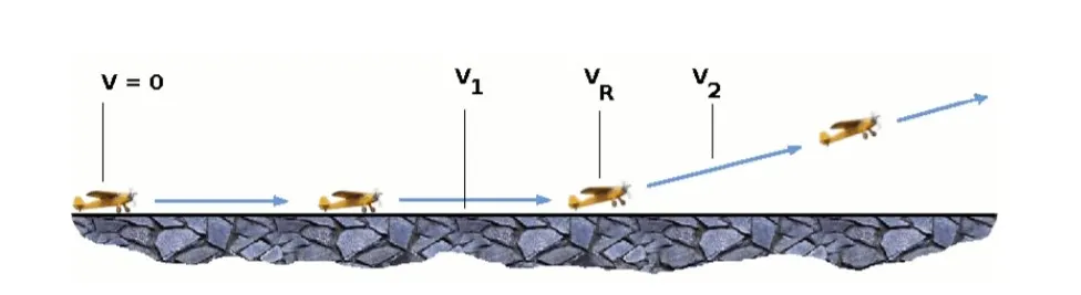
As the aircraft gains speed, air passes faster and faster over its wings and lift is created. Instruments onboard the aircraft display this airspeed, which equals not only the speed of the plane relative to the ground, but also the speed of any wind that may be blowing toward the aircraft (aircraft normally take off headed into the wind). When the airspeed reaches a certain predetermined point known as rotation speed, the pilot manipulates panels on the tail of the aircraft to rotate the nose of the plane upward. This creates even stronger lift and the plane leaves the ground.
Rotation speed, abbreviated VR, is one of three important airspeed settings calculated before every flight.
The others are V1 - the speed beyond which a safe stop on a runway is no longer possible; and V2 - the minimum speed needed to keep a plane flying should an engine fail after the aircraft surpasses V1. Some of the factors affecting VR and V2 are the weight of the aircraft, the air temperature and the altitude of the airport. The heavier the aircraft, the more lift, and thus speed is needed to get it off the ground. Aircraft also need to go faster to y on a hot day than on a cool day. Hot air is less dense than cool air and less density produces less lift for the same speed.
Similarly, the higher the altitude, the less dense the air. Aircraft need more speed to leave the ground at a place like Denver than at a place like New York, with all other factors such as weight being equal. Some of these factors also are important in calculating V1, although the key factor is the length of the runway that is being used.
Most large jets leave the ground at about 160 miles per hour and initially climb at an angle in excess of 15 degrees. The angle of a plane's wings to the air owing around them is extremely important to maintaining lift. If the so-called angle of attack is too severe, the ow of air around the wings becomes disrupted and the plane loses lift.
To make an aircraft more aerodynamically effcient, the wheels on which an aircraft rolls when it is on the ground are retracted into a cavity in the belly of the plane after it is airborne. There is less drag (wind resistance), and an aircraft can fly faster when its landing gear is retracted.
Tyre design :=>
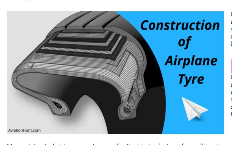
When it comes to safety tyres are one of the most important components of aircraft. They help to absorb the shock of landing and provide cushioning. It also provides the necessary traction for braking and stopping of an aircraft.
An aircraft tyre is designed to withstand extremely heavy loads while landing, take off, taxing and parking. The number of wheels required for aircraft increases with the weight of the aircraft, as the weight of the aeroplane needs to be distributed more evenly.
A Boeing 737NG & 737MAX uses 6 wheels, Boeing 787 uses 10 wheels, Boeing 777 uses 14 wheels and Airbus A380 uses 22 wheels. Aircraft tyres work under extreme conditions, carrying up to 340 tons and accelerating at over 250 km/hour at takeoff, in addition to enduring varied environmental stress when in flight and taxiing.
Design and Construction of Aircraft tyre
Carcass plies are used to form the tire. They are sometimes called casing plies. An aircraft tyre is constructed for the purpose it serves.
1. They support the weight of an aircraft while it is on the ground.
2. It also provides the necessary traction for braking and stopping of an aeroplane.
3. Tyre also helps to absorb the shock of landing and provide cushioning the roughness of takeoff, roll-out, and taxi operations.
Unlike an automobile or truck tyre, it does not have to carry a load for a long period of continuous operation. However, an aircraft tyre absorbs the high impact loads of landing and also it’s operating at high speeds for a short time when required.
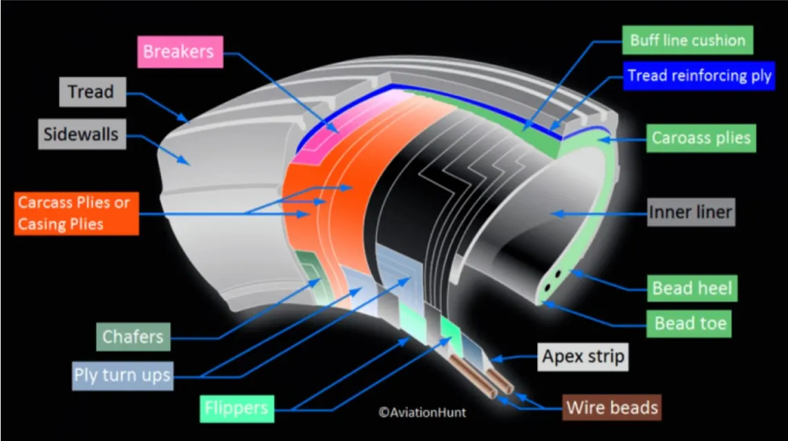
Some technical aspects of the tyre :
Retreading – Retreading is methods of restoring a worn tyre by renewing the tread area or by renewing the tread area plus one or both sidewalls. Repairs are included in the tyre retreading process.
Load Rating – Load rating is the maximum permissible load at a specified inflation pressure.
Ply Rating – Ply Rating is used to identify the maximum recommended load rating and inflation pressure for a specified tyre. It is an index of tyre strength.
Speed Rating – The speed rating is the maximum takeoff speed to which the tyre has been tested.
Skid Depth – Skid depth is the distance between the tread surface and the deepest groove as measured in the mould.
Aircraft tyres must have an approved speed and load rating and have sufficient clearance when retracted through landing gear to allow for tyre growth. Tyre growth is the increase in the size of the tyre due to centrifugal forces at high speed.
Aircraft tyres may be Tube-type or Tubeless
Tubeless tyres are more advantageous over tube-type. There is no longer the use of tube-type tyre in recent aviation. Nowadays all airliners are using tubeless tyres. Tubeless that are meant to be used without a tube has the word TUBELESS on the sidewall of the tyre.
Aircraft tyres may be Radial or Bias
Almost all airliners are using Radial tyre. Bias is an older design, and it’s mainly used for road vehicles. Radial tyres have the word RADIAL on the sidewall. Radial tires are more expensive than bias-ply tyres. Radial tires are in demand because of their lower life cycle cost and long term value.
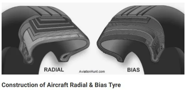
Radial tyre construction :
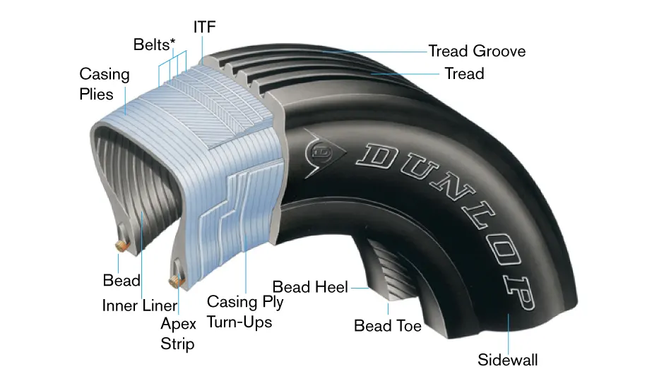
Radial tires are the most modern design of aircraft tyres. It is a design that is similar to that of car tyres. Typically, the radial tyre offers more landings per tread and lighter weight than a bias tyre; though sometimes at the expense of retread lives.
Radial aircraft tyres differ to bias aircraft tyres in that the plies all run radially from bead to bead at approximately 90° to the centre-line of the tyre. Angled belt plies are laid between the tread and the top casing ply, resulting in a flatter tread and adding strength to the tyre.
Bias ply tyre :
A bias-ply tyre has the fabric bias oriented with and across the direction of rotation and the sidewall. Since fabric can stretch on the bias, the tyre is flexible and can absorb loads. Tyre strength is obtained by adding plies.
Rolling resistance :=>
Rolling resistance is one of the forces that act to oppose the motion of a cyclist. It is caused mainly because of deformation of the tyre and can be understood by thinking about:
1. energy losses due to heat (hysteresis)
2. the forces pushing on the tyre.
Energy is lost as heat
As the tyre comes into contact with the road, it changes shape as it is compressed (pushed in a bit). This compression causes parts of the rubber tube and the casing of the tyre to heat up. It also causes the tread on the outside of the tyre to heat up as it comes into contact with the road. A tyre with knobbly tread will have a lot more rolling resistance than a smooth tyre because there will be more rubber being compressed and so there will be more heat.
The tyre is a bit like a spring or a rubber band. Some of the energy is stored as the tyre becomes compressed (squeezed in). As the tyre comes back off the road, there is not as much of this stored energy returned because some of it has gone towards making the tyre heat up. This loss of available energy due to heating is called hysteresis. This means there will be less energy available to make the bike go faster.
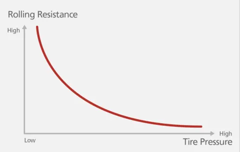
If you feel the temperature of your tyres when you have been biking fast, you will notice this heat. If your tyres are not pumped up hard, there will be even more heat created.
The force of rolling resistance does not change at higher speeds. However, because there is a lot more heat being produced at higher speeds, the cyclist uses more power (energy per second) to work against rolling resistance.
Forces on the front part of the tyre are greater
Forces on a tyre
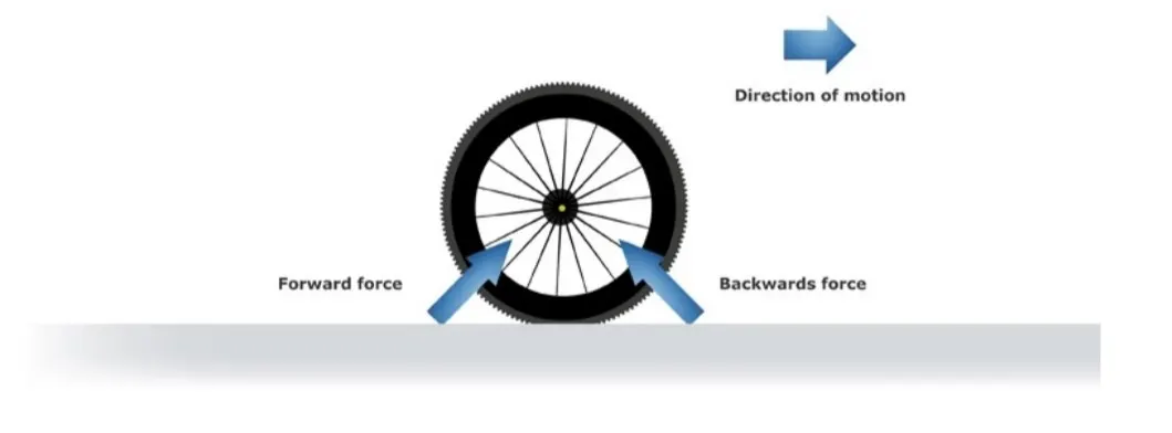
Rolling resistance happens because the force pushing backwards against the tyre as it comes into contact with the road is bigger than the force pushing forwards as it leaves.
As the front part of the tyre touches the road, it takes a lot of force to squeeze in the tyre. This causes a backwards force on the wheel. As the tyre comes back off the road, there is a force pushing forwards on the wheel, but this forwards force is not as great. This is because of internal friction in the tyre.
If you could design a tyre that didn’t have internal friction and didn’t heat up, the force at the front section of the tyre contacting the road would be the same size as the force on the back section. This would mean zero rolling resistance, assuming there was no energy loss due to compression of the road surface.
Some things that affect rolling resistance
Rolling resistance depends on the mass of the cyclist and the bike, cornering, the design of your tyres, tyre pressure and road surface.
Mass – more mass means more downwards force due to gravity onto the road. This results in more tyre compression so rolling resistance increases. Carrying things like extra water bottles increases your rolling resistance.
Cornering – going through corners causes track cyclists to slow down, partly because cornering results in a greater downwards force into the track, which increases rolling resistance. (Cornering also increases rolling resistance because the rubber is twisting sideways on the road a bit, and this twisting produces more friction and heat.)
Design of tyres – choosing materials and construction that don’t heat up as much will result in less rolling resistance. One way to do this is to make your tubes out of specialised latex rubber. Racing tyres are very smooth, narrow and pumped up hard. The casing is also designed to minimise heat loss as it deforms. With as little of the tyre being compressed in as possible, there will not be as much of this heating effect, so there will be more energy available for more speed. There are many options for cyclists to consider.
Road or track surface – wooden cycle tracks contribute to a very low rolling resistance. Roughsealed roads have more rolling resistance. Grass and soft dirt surfaces are much greater. If the surface can be deformed, this increases rolling resistance markedly.
Choosing tyre materials and construction that don’t heat up as much will result in less rolling resistance.
Calculating rolling resistance
This equation is used to calculate the force of rolling resistance from each tyre:
FRR = CRR x weight
FRR is the rolling resistance force.
CRR is the coefficient of rolling resistance (a number used to rate each tyre at a given pressure),
weight is the force due to gravity being exerted on each tyre (= mass (kilograms) x 9.8).
This equation shows that speed does not affect the force due to rolling resistance. The type of tyre and the mass of the bike plus rider are the only two variables.
Tyre pressure =>
An aircraft tire or tyre is designed to withstand extremely heavy loads for short durations.The number of tires required for aircraft increases with the weight of the aircraft, as the weight of the airplane needs to be distributed more evenly. Aircraft tire tread patterns are designed to facilitate stability in high crosswind conditions, to channel water away to prevent hydroplaning, and for braking effect.
Aircraft tires also include fusible plugs (which are assembled on the inside of the wheels), designed to melt at a certain temperature. Tires often overheat if maximum braking is applied during an aborted takeoff or an emergency landing. The fuses provide a safer failure mode that prevents tire explosions by deflating in a controlled manner, thus minimizing damage to aircraft and objects in the surrounding environment.
Inflation :
Each of the twelve Boeing 777-300ER main tires is inflated to 220 psi (15 bar; 1,500 kPa), weighs 120 kg (260 lb), has a diameter of 134 cm (53 in) and is changed every 300 cycles while the brakes are changed every 2000 cycles.
Aircraft tires generally operate at high pressures, Inflation up to 200 psi (14 bar; 1,400 kPa) for airliners, and even higher for business jets.
Tests of airliner aircraft tires have shown that they are able to sustain pressures of maximum 800 psi (55 bar; 5,500 kPa) before bursting.
Aircraft tires are usually inflated with nitrogen to minimize expansion and contraction from extreme changes in ambient temperature and pressure experienced during flight.
Brake forces and landing=>
Bringing at aircraft down to the runway from 37,000 feet is only part of the challenge. It’s not over until the aircraft is safely parked at its gate. In order to do this, pilots have a number of systems available to slow the aircraft down, even in a blizzard on a snowcovered runway.
The 787 braking system:
Stopping a 200-tonne aircraft landing at 180 mph requires a lot of braking force. To do this, the 787 has one brake unit on each of the eight wheels on the main gear assembly.
On other aircraft types, the brake units are powered by the hydraulics system. An electrical signal is sent from the flight deck to hydraulic actuators near the main landing gear. Here, hydraulic fluid at 3,000 pound per square inch is used to force the brake unit against the wheel, thus slowing it down.
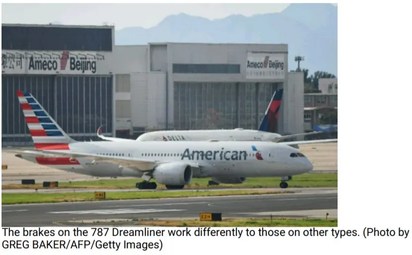
That’s the case on the 787 Dreamliner. Designers did away with the use of the hydraulic system and all its associated architecture and instead used electricity to power the brakes. When the pilots press on the brake pedals, an electrical signal is sent to the brake unit on the wheel. Here, electrically powered actuators are used to press the carbon brake disc against the wheel, slowing it down.
Electric brakes
The brake system on the 787 Dreamliner is controlled by the pilots pressing the tops of the rudder pedals under their feet, demanding the rate of braking which they require. This sends an electronic signal to the Left and Right Brake System Control Units (BSCUs).
These then send signals to the four Electronic Brake Actuator Controllers (EBAC) which control the rate of braking on the wheels. Each wheel has four Electric Brake Actuators (EBA), a kind of piston which presses against the carbon brake discs.
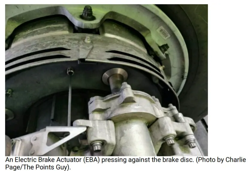
The brake disks themselves are made up of two parts. Firstly, there are the rotors. These are connected to the wheel by drive tabs (in the video below they are the black rectangles on the rotor disks). As these drive tabs are in contact with the inside of the wheel, they spin at the same speed. Depending on the brake manufacturer, there are either four or five of these rotors on each brake assembly.
The second part of the disks are the stators. These sit around each rotor and are fixed in place and thus don’t move. As the wheel turns, the rotors spin round inside the stators.
When the brakes are applied, the four EBAs apply pressure to the first stator. This in turn squeezes the stationary stators up against the spinning rotors and it’s this friction which slows the wheel down.
Anti-skid protection
When landing on slippery runways, there’s a chance that the wheels may start to skid as the brakes are applied. To stop this from happening and to maintain maximum effective braking, each wheel has anti-skid protection.
Using a variety of sources to determine the aircraft speed, the brake units know how fast the wheels should be spinning. If that speed drops significantly, it’s because the current brake pressure on that wheel is too great and the wheel is just skidding over the surface.
In this situation, the anti-skid system automatically reduces the braking on that wheel to a point where the skid stops before reapplying the pressure. All this is done in a fraction of a second.
Autobrake
Pressing on the brakes is pretty straight forward when taxiing in a straight line at low speed. However, when we’re landing in strong winds, it can be a little tricky. We need to use our feet on the rudder pedals to line the nose of the aircraft up with the runway centerline at the last moment. Then, whilst holding that position, slide our feet up to press the toe brakes. Really not very easy when moving at 160 mph.
To help us get the braking underway as soon as we touch down, we have the autobrake system.This provides automatic braking at a preselected rate as soon as the aircraft senses that it is on the ground. It also provides full braking pressure in the case of a rejected takeoff if the speed is above 85 knots (98 mph).
Bottom line
Bringing an aircraft to a safe stop is the most important part of a flight. In order to do this, pilots have a number of facilities available to them.
The brakes bear the brunt of the hard work with the spoilers and reverse thrust lending a helping hand to ensure maximum efficiency. The autobrake system helps keep the deceleration nice and smooth whilst the anti-skid system reduces the distances needed to stop by modulating the brakes on individual wheels and stopping them from skidding.
Aircraft can also depart with part of the braking system not working. By carrying out a performance calculation before every takeoff and landing, we ensure that the aircraft will stop safely in the given conditions, even at maximum takeoff weight.
6. A. With necessary assumptions, calculate the force and power required to push / pull an aircraft by a towing vehicle?
ANS:
PULLING AN AIRPLANE
FORCE REQUIRED TO PULL AN AIRPLANE:
The force to move an airplane on an absolute flat runway with no wind at constant low speed is equal to the rolling resistance between the plane and the tarmac.
The rolling resistance for the air plane can be calculated as
Fr = c mr ag (1)
where
Fr = rolling resistance (N, lbf)
c = rolling resistance coefficient
mr = rolling mass (kg, lbm)
ag = acceleration of gravity (9.81 m/s2)
Example - Force required to pull an airplane at constant low speed on tarmac
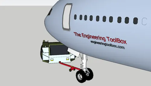
If the mass of a plane is 40000 kg and the rolling coefficient between the aircraft wheel and the tarmac is 0.02 - the force required to overcome the rolling resistance can be calculated as
Fr = 0.02 (40000 kg) (9.81 m/s2)
= 7848 N
This force can be delivered by a pulling truck or - as occasionally seen - by a number of pulling people. Enough weight for the pullers are required to create friction forces against the tarmac that equals the plane rolling resistance.
The friction force for the puller can be calculated to
Ff = μ W
= μ mf ag (2)
where
Ff = frictional force (N, lb)
μ = friction coefficient
W = weight (N, lbf)
mf = friction mass (kg)
Example - Required Mass for Pulling Truck
The friction coefficient between a pulling truck rubber wheels and dry tarmac is 0.9. Since pulling trucks are connected to air crafts nose wheels close to tarmac we simplify the calculation of required truck mass to
mf = (7848 N) / (0.9 (9.81 m/s2))
= 889 kg
Example - Air Craft Pulled by People
When persons participates in aircraft pulling there is normally an offset between the rope connected to the air craft nose wheel and the tarmac. It is common for persons to bend over with the rope over the shoulder or holding it in the hands.
The horizontal friction force between the persons shoes and the tarmac must be equal or larger than the air plane rolling resistance. The minimum required vertical force - or minimum weight of the people - depends on the bending angle as illustrated in the vector diagram below.
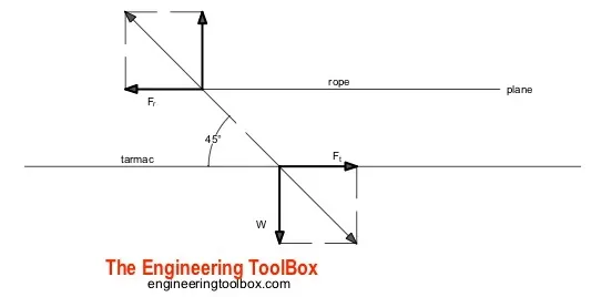
If they bend over 45o - the vertical force or weight equals to the horizontal force. With rubber shoes and the same friction coefficient as above for the truck the weight of the people should be 889 kg. With an average weight of 80 kg/person - the number of persons can be calculated to
n = (889 kg) / (80 kg/person)
= 11.1
= 12
With a more realistic bending angle 60o - the minimum vertical force or weight can be calculated as
W = tan(60o) (7848 N)
= 13593 N
The minimum mass of people to achieve this weight can be calculated as
mf = W / ag
= (13593 N) / (9.81 m/s2)
= 1386 kg
With an average weight of 80 kg/person - the minimum number of persons can be calculated to
n = (1386 kg) (80 kg/person)
= 17.3
= 18