Project-1: Powertrain for aircraft in runways
POWERTRAIN OF AIRCRAFT
1.Weights of Airplanes
MTOW = Maximum take-off weight, MLW = Maximum landing weight, TOR = Take-off run (SL, ISA+15°, MTOW), LR = Landing run (SL, ISA+15°, MLW)
| Type | MTOW [kg] | MLW [tons] | TOR [m] | LR [m] | ICAO category | FAA category |
|---|---|---|---|---|---|---|
| Antonov An-225 | 640,000 | 591.7 | 3500 | Heavy | Super | |
| Scaled Composites Model 351 Stratolaunch | 589,670 | 3660 | Heavy | Super | ||
| Airbus A380-800 | 575,000 | 394 | 3100 | 1930 | Super | Super |
| Boeing 747-8F | 447,700 | 346.091 | 3100 | 1800 | Heavy | Heavy |
| Boeing 747-8 | 443,613 | 306.175 | 3100 | Heavy | Heavy | |
| Boeing 747-400ER | 412,770 | 295.742 | 3090 | Heavy | Heavy | |
| Antonov An-124-100M | 405,060 | 330 | 2520 | 900 | Heavy | Heavy |
| Boeing 747-400 | 396,900 | 295.742 | 3018 | 2179 | Heavy | Heavy |
| Lockheed C-5 Galaxy | 381,000 | 288.417 | 2530 | 1494 | Heavy | Heavy |
| Boeing 747-200 | 377,840 | 285.700 | 3338 | 2109 | Heavy | Heavy |
| Boeing 747-300 | 377,840 | 260.320 | 3222 | 1905 | Heavy | Heavy |
| Airbus A340-500 | 371,950 | 240 | 3050 | 2010 | Heavy | Heavy |
| Airbus A340-600 | 367,400 | 256 | 3100 | 2100 | Heavy | Heavy |
| Boeing 777F | 347,800 | 260.816 | 2830 | Heavy | Heavy | |
| Boeing 777-300ER | 351,800 | 251.29 | 3100 | Heavy | Heavy | |
| Boeing 777-200LR | 347,450 | 223.168 | 3000 | Heavy | Heavy | |
| Boeing 747-100 | 340,200 | 265.300 | Heavy | Heavy | ||
| Airbus A350-1000 | 308,000 | 233.5 | Heavy | Heavy | ||
| Boeing 777-300 | 299,370 | 237.683 | 3380 | Heavy | Heavy | |
| Boeing 777-200ER | 297,550 | 213.00 | 3380 | 1550 | Heavy | Heavy |
| Airbus A340-300 | 276,700 | 190 | 3000 | 1926 | Heavy | Heavy |
| McDonnell Douglas MD-11 | 273,300 | 185 | 2990 | 1890 | Heavy | Heavy |
| Airbus A350-900 | 270,000 | 175 | 2670 | 1860 | Heavy | Heavy |
| Ilyushin Il-96M | 270,000 | 195.04 | 3115 | 2118 | Heavy | Heavy |
| McDonnell Douglas DC-10 | 256,280 | 183 | 2990 | 1890 | Heavy | Heavy |
| Boeing 787-9 | 254,000 | 192.777 | 2900 | Heavy | Heavy | |
| Boeing 787-10 | 254,000 | 201.849 | Heavy | Heavy | ||
| Airbus A340-200 | 253,500 | 181 | 2990 | Heavy | Heavy | |
| Ilyushin IL-96-300 | 250,000 | 175 | 2600 | 1980 | Heavy | Heavy |
| Airbus A330-300 | 242,000 | 185 | 2500 | 1750 | Heavy | Heavy |
| Airbus A330-200 | 242,000 | 180 | 2220 | 1750 | Heavy | Heavy |
| Lockheed L-1011-500 | 231,300 | 166.92 | 2636 | Heavy | Heavy | |
| Boeing 787-8 | 228,000 | 172.365 | 3300 | 1695 | Heavy | Heavy |
| Lockheed L-1011-200 | 211,400 | Heavy | Heavy | |||
| Ilyushin IL-86 | 208,000 | 175 | Heavy | Heavy | ||
| Boeing 767-400ER | 204,000 | 158.758 | 3414 | Heavy | Heavy | |
| Airbus A300-600R | 192,000 | 140 | 2385 | 1555 | Heavy | Heavy |
| Boeing 767-300ER | 187,000 | 136.08 | 2713 | 1676 | Heavy | Heavy |
| Concorde | 185,000 | 111.1 | 3440 | 2220 | Heavy | Heavy |
| Airbus A300-600 | 163,000 | 138 | 2324 | 1536 | Heavy | Heavy |
| Boeing 767-300 | 159,000 | 136.078 | 2713 | 1676 | Heavy | Heavy |
| Airbus A310-300 | 157,000 | 124 | 2290 | 1490 | Heavy | Heavy |
| Vickers VC10 | 152,000 | 151.9 | Heavy | Heavy | ||
| Boeing 707-320B | 151,000 | 97.5 | Heavy | Heavy | ||
| Boeing 707-320C | 151,000 | 112.1 | Heavy | Heavy | ||
| Douglas DC-8-61 | 147,000 | Heavy | Heavy | |||
| Airbus A310-200 | 142,000 | 123 | 1860 | 1480 | Heavy | Heavy |
| Airbus A400M | 141,000 | 122 | 980 | 770 | Heavy | Heavy |
| Douglas DC-8-32 | 140,000 | Heavy | Heavy | |||
| Douglas DC-8-51 | 125,000 | Medium | Large | |||
| Boeing 757-300 | 124,000 | 101.6 | 2550 | 1750 | Medium | Large |
| Boeing 707-120B | 117,000 | 86.3 | Medium | Large | ||
| Boeing 757-200 | 116,000 | 89.9 | 2347 | 1555 | Medium | Large |
| Boeing 720B | 106,000 | 79.5 | Medium | Large | ||
| Boeing 720 | 104,000 | 79.5 | Medium | Large | ||
| Tupolev Tu-154M | 104,000 | 80 | Medium | Large | ||
| Tupolev Tu-204SM | 104,000 | 87.5 | 2250 | Medium | Large | |
| Convair 880 | 87,500 | Medium | Large | |||
| Boeing 737-900 | 85,000 | 66.36 | 2500 | 1704 | Medium | Large |
| Boeing 737-900ER | 85,000 | 71.35 | 2804 | 1829 | Medium | Large |
| Boeing 727-200 Advanced | 84,000 | 70.1 | Medium | Large | ||
| Airbus A321-100 | 83,000 | 77.8 | 2200 | 1540 | Medium | Large |
| Boeing 737-800 | 79,000 | 65.32 | 2308 | 1634 | Medium | Large |
| Boeing 727-200 | 78,000 | 68.1 | Medium | Large | ||
| McDonnell-Douglas MD-83 | 73,000 | 63.28 | Medium | Large | ||
| Boeing 727-100 | 72,500 | 62.4 | Medium | Large | ||
| Boeing 727-100C | 72,500 | 62.4 | Medium | Large | ||
| McDonnell-Douglas MD-90-30 | 71,000 | 64.41 | 2165 | 1520 | Medium | Large |
| de Havilland Comet 4 | 70,700 | Medium | Large | |||
| Boeing 737-700 | 70,000 | 58.06 | 1921 | 1415 | Medium | Large |
| Airbus A320-100 | 68,000 | 66 | 1955 | 1490 | Medium | Large |
| Boeing 737-400 | 68,000 | 54.9 | 2540 | 1540 | Medium | Large |
| de Havilland Comet 3 | 68,000 | Medium | Large | |||
| Boeing 377 | 67,000 | Medium | Large | |||
| Boeing 737-600 | 66,000 | 54.66 | 1796 | 1340 | Medium | Large |
| Airbus A220-300 | 65,000 | 57.61 | 1890 | 1494 | Medium | Large |
| Hawker Siddeley Trident 2E | 65,000 | Medium | Large | |||
| Airbus A319 | 64,000 | 62.5 | 1850 | 1470 | Medium | Large |
| Boeing 737-300 | 63,000 | 51.7 | 1939 | 1396 | Medium | Large |
| Boeing 737-500 | 60,000 | 49.9 | 1832 | 1360 | Medium | Large |
| Airbus A220-100 | 59,000 | 50.80 | 1463 | 1356 | Medium | Large |
| Airbus A318 | 59,000 | 57.5 | 1375 | 1340 | Medium | Large |
| Boeing 717-200HGW | 55,000 | 47.174 | 1950 | Medium | Large | |
| Douglas DC-7 | 55,000 | Medium | Large | |||
| de Havilland Comet 2 | 54,000 | Medium | Large | |||
| Boeing 717-200BGW | 50,000 | 46.265 | 1950 | Medium | Large | |
| de Havilland Comet 1 | 50,000 | Medium | Large | |||
| Douglas DC-6A | 48,600 | Medium | Large | |||
| Douglas DC-6B | 48,500 | Medium | Large | |||
| Embraer 190 | 48,000 | 43 | 2056 | 1323 | Medium | Large |
| Caravelle III | 46,000 | Medium | Large | |||
| Fokker 100 | 46,000 | 39.95 | 1621 | 1350 | Medium | Large |
| Douglas DC-6 | 44,000 | Medium | Large | |||
| Avro RJ-85 | 42,000 | 36.74 | Medium | Large | ||
| Handley Page Hermes | 39,000 | Medium | Large | |||
| Embraer 175 | 37,500 | 32.8 | 2244 | 1304 | Medium | Large |
| Bombardier CRJ900 | 36,500 | 33.345 | 1778 | 1596 | Medium | Large |
| Embraer 170 | 36,000 | 32.8 | 1644 | 1274 | Medium | Large |
| Bombardier CRJ700 | 33,000 | 30.39 | 1564 | 1478 | Medium | Large |
| Douglas DC-4 | 33,000 | Medium | Large | |||
| Vickers Viscount 800 | 30,400 | Medium | Large | |||
| Bombardier Q400 | 28,000 | 28.01 | 1219 | 1295 | Medium | Large |
| Bombardier CRJ200 | 23,000 | 21.319 | 1918 | 1479 | Medium | Large |
| ATR 72-600 | 22,800 | 22.35 | 1333 | 914 | Medium | Large |
| Saab 2000 | 22,800 | 21.5 | 1300 | Medium | Large | |
| Embraer ERJ 145 | 22,000 | 19.3 | 2270 | 1380 | Medium | Large |
| ATR 42-500 | 18,600 | 18.3 | 1165 | 1126 | Medium | Small |
| Saab 340 | 13,150 | 12.930 | 1300 | 1030 | Medium | Small |
| Embraer 120 Brasilia | 11,500 | 11.25 | 1560 | 1380 | Medium | Small |
| BAe Jetstream 41 | 10,890 | 10.570 | 1493 | 826 | Medium | Small |
| Learjet 75 | 9,752 | 8.709 | 1353 | 811 | Medium | Small |
| Pilatus PC-24[ | 8,300 | 7.665 | 893 | 724 | Medium | Small |
| Embraer Phenom 300 | 8,150 | 7.65 | 956 | 677 | Medium | Small |
| Beechcraft 1900D | 7,765 | 7.605 | 1036 | 853 | Medium | Small |
| Cessna Citation CJ4 | 7,761 | 7.103 | 1039 | 896 | Medium | Small |
| de Havilland Hercules | 7,000 | Medium | Small | |||
| Embraer Phenom 100 | 4,800 | 4.43 | 975 | 741 | Light | Small |
2. Air Speed & Ground Speed
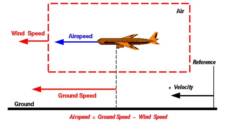
Air speed is simply the speed at which an aircraft is moving relative to the air it is ying in. It’s also the speed at which the air is owing around the aircraft’s wings.
Ground speed, on the other hand, is the aircraft’s speed relative to the ground. Ground speed is simply the sum of airspeed and wind speed.
One thing that should be noted here is that ground speed is horizontal rather than vertical speed – an aircraft climbing completely vertically would have a ground speed of zero. In other words, while airspeed is what determines whether there is enough airow around an aircraft to make it y, ground speed is what determines how fast an aircraft will get to its destination
3. Why is it not recommended to use aircraft engine power to move it on the ground at Airport?
Most aircraft are capable of moving themselves backwards on the ground using reverse thrust, a procedure called as a powerback, it is not typically done due to the following reasons:
The jet blast from the engines can damage the terminal building and nearby equipment. It can even throw away people standing nearby. Engines can blow sand and debris. Engines can suck in sand and debris which can cause serious damage to the engine. It is easier for the truck driver to see the surroundings better than the pilot sitting in the cockpit with limited windows. The pushback truck driver knows the airport better than the pilot. The plane engines are very loud. This noise can add up substantially when multiple planes are moving around the airport. It won't be a pleasant experience for people sitting inside the terminal, as most people don't even like the sound of powerful motor-bikes. It saves fuel. Virgin Atlantic had proposed a new system in which the pushback trucks will push the plane all the way to the runway to save fuel and reduce impact on nearby environment.
4. How an aircraft is pushed to runway when its ready to take off?
Taxiing is the movement of an aircraft on the ground, under its own power, in contrast to towing or push-back where the aircraft is moved by a tug. The aircraft usually moves on wheels, but the term also includes aircraft with skis or oats (for water-based travel).
The power for taxiing comes from the engines itself. If it is a propeller powered aircraft, the propeller provides thrust and pulls the aircraft, like it would in air. If it is a jet engine, the exhaust air that comes out of the engine creates a forward force due to Newton's third law and moves the airplane.
Airliners have nose wheel steering, controlled by a cockpit control called a tiller. The tiller allows nose wheel to rotate at quite extreme angles making tighter turns possible. It also reduces the fuel consumption as you do not need much engine power during taxiing. If rudders were used, the power has to be increased to make sure sucient air ows over the rudder surface to make it effective.
Once on the take off roll and the airplane gains sucient speed i.e. enough air ows over the rudders, pilots go back to using the rudder pedals to maintain the centre line.
Some large airplanes with multi wheel main gears have a tendency to scrub the tyres on the tarmac when nose wheel is steered. To counter this problem, an automatic main gear steering is inbuilt in the aircraft. This makes the main gears turn the opposite direction to that of the nose wheel, greatly decreasing the wear on the tyres.
Small general aviation aircraft uses the rudder for turns during taxi. They don't have a separate control for nose wheel. In such airplanes, to make tighter turns, you could use differential braking. That is, if you want to make a tight turn for example to the left, you would push the upper part of your left rudder pedal which would apply left braking. This allows the airplane to make a sharper turn to the left.
5. Take off power, tyre design, rolling resistance, tyre pressure, brake forces when landing.
Power:
Take off is the phase of ight in which an aerospace vehicle leaves the ground and becomes airborne and the power required to fullll this task is Take off power. For aircraft that take off horizontally, this usually involves starting with a transition from moving along the ground on a runway. It is needed becuase for a given aircraft, the takeoff speed is usually dependent on the aircraft weight; the heavier the weight, the greater the speed needed. So speed is achieved by running on runways. The speeds needed for takeoff are relative to the motion of the air (indicated airspeed). A headwind will reduce the ground speed needed for takeoff, as there is a greater ow of air over the wings. Typical takeoff air speeds for jetliners are in the range of 240–285 km/h (130–154 kn; 149–177 mph). Light aircraft, such as a Cessna 150, take off at around 100 km/h (54 kn; 62 mph). Ultralights have even lower takeoff speeds. After this the nose is raised to a nominal 5°–15° nose up pitch attitude to increase lift from the wings and affect liftoff.
So, power required to do all this task is accounted into take off power. Most takeoffs use "derated" thrust to save engine wear. For each takeoff, performance is calculated, the necessary power setting is determined and the thrust setting is made. When using this method during takeoff, it is always possible to increase to full power if the situation requires. The captain always makes the nal decision whether to use full thrust or derate.
Tyres :
When it comes to safety, tyres are one of the most important components of aircraft. They help to absorb the shock of landing and provide cushioning. It also provides the necessary traction for braking and stopping of an aircraft. And all this is for short times. An aircraft tyre is designed to withstand extremely heavy loads while landing, take off, taxing and parking. The number of wheels required for aircraft increases with the weight of the aircraft, as the weight of the aeroplane needs to be distributed more evenly.
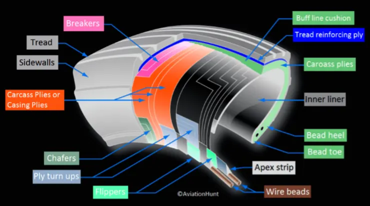
Tyres are radial type and tubeless. Aircraft tyres are conductive too as they are manufactured with tread rubber with conducting compounds to permit earthing of static charges.
Carcass plies are used to form the tire. They are sometimes called casing plies. An aircraft tyre is constructed for the purpose it serves.
They support the weight of an aircraft while it is on the ground. It also provides the necessary traction for braking and stopping of an aeroplane. Tyre also helps to absorb the shock of landing and provide cushioning the roughness of takeoff, roll-out, and taxi operations.
Rolling Resistance:
Rolling resistance, is the force resisting the motion when a body rolls on a surface. It is experienced during take off and landinf of aircraft.
Factors that contribute to rolling resistance are the amount of deformation of the wheels, the deformation of the roadbed surface, and movement below the surface. Additional contributing factors include wheel diameter, load on wheel, surface adhesion, sliding, and relative micro-sliding between the surfaces of contact.
We also have a constant for calculation of rolling resistance force known as coecient of rolling resistance depnds upon typre pressure and velocity.
c = 0.005 + (1 / p) (0.01 + 0.0095 (v / 100)2)
Where,
c = coecient of rolling resistance
p = tyre pressure in bar
v = velocity of vehicle in Km/H.
Aircraft tyre pressure:
Aircraft tires generally operate at high pressures, up to 200 psi (14 bar; 1,400 kPa) for airliners, and even higher for business jets. The main landing gear on the Concorde was typically inated to 232 psi (16.0 bar), whilst its tail bumper gear tires were as high as 294 psi (20.3 bar). Tests of airliner aircraft tires have shown that they are able to sustain pressures of maximum 800 psi (55 bar) before bursting. During the tests the tires have to be lled with water, to prevent the test room being blown apart by the energy that would be released by a gas when the tire bursts. Aircraft tires are usually inated with nitrogen to minimize expansion and contraction from extreme changes in ambient temperature and pressure experienced during ight. Dry nitrogen expands at the same rate as other dry atmospheric gases (normal air is about 80% nitrogen), but common compressed air sources may contain moisture, which increases the expansion rate with temperature.
Brake forces when landing:
The three primary methods of achieving deceleration on the runway during the landing roll or a rejected take off are engine power, brakes and mechanical spoilers. Effective and co-ordinated use of whichever of these are available will result in a stopping distance appropriate to the available runway ahead, or the desired runway exit point if sooner. The key to success is the properly co-ordinated use of all the available methods.
Engine Power: In this the focus is to select all thrust/power levers to the ground idle position promptly, and if available, continue the action through to the selection of reverse thrust or reverse propeller pitch. Selection at these relatively high speeds must be symmetrical because otherwise, directional control may be prejudiced.
Wheel Brakes: It depends upon sucient friction existing between the tyres and the runway surface achieved through freely rotating wheels. These ensure adequate wheel rotation exists and is maintained before the commanded brake pressure is transmitted to the brake units and takes effect. An electrical signal is sent from the ight deck to hydraulic actuators near the main landing gear. Hydraulic uid pressure is used to force the brake unit against the wheel, thus slowing it down. But this resulted in less eciency due to increase in weight. So we switched to electrical braking, i.e. when the pilots press on the brake pedals, an electrical signal is sent to the brake unit on the wheel. Here, electrically powered actuators are used to press the carbon brake disc against the wheel, slowing it down. Here, when the pilots press on the brake pedals, it sends an electronic signal to the Left and Right Brake System Control Units (BSCUs). These then send signals to the four Electronic Brake Actuator Controllers (EBAC) which control the rate of braking on the wheels. Each wheel has four Electric Brake Actuators (EBA), a kind of piston which presses against the carbon brake discs.
Mechanical Spoilers : This is done by increasing aerodynamic drag on the moving aircraft. This can be achieved by raising upper wing surface panels called ground spoilers or by operation of a tail cone ‘clamshell’ type air brake. Both systems can also be used in the air on some aircraft types as in-ight air brakes, but the extent of their operation may be less in the airborne case than in the ground (weight on wheels) case.
6. With necessary assumptions, calculate the force and power required to push / pull an aircraft by a towing vehicle.
Assumptions :
Weight of the Aircraft (Airbus A-380) = 575000kg
Rolling Resistance Coecient of an aircraft tire(μrr) = 0.004
Wight of the Towing Tractor = 50000kg
Rolling Resistance Coecient of Towing Vehicle(μrr) = 0.001
Then,
Rolling Resistance Force of Tow Tractor = μrr × m. g = 0.001 × 50000 × 9.81 = 0.49KN
Rolling Resistance Force of aircraft = μrr × m. g = 0.004 × 575000 × 9.81 = 22.56KN
Total Rolling Resistance Force = Rolling Resistance Force of aircraft + Towing Tractor = 0.49 + 22.56
Total Rolling Resistance Force = 23.05KN
Air Drag Force :The drag force is the force that occures due to the Air Strike effect on the vehicle when it moves. The vehicle moves through a air medium of particular dencsity value with certain speed this causes the air strike against the vehicle body and it causesDrag Force on the vehicle.
The Aerodynamic Drag is given by the following expression
fad = 0.5* ρ *A *V^2 *Cd
Where,
ρ = Density of Air Medium
A = Frontal Area Of the Vehicle which strike the Air
V = Velocity with which the vehicle moves
Cd = Coecient of Dragwhich varies different shapes of the frontal area.
Calculation:
Let us assume,
The Velocity of the Aircraft while Towing = 30KMPH = 8.33m/s
Density of Air medium(ρ) = 1.225
The Frontal area of the Aircraft(A) = 20m^2
The Coecient of Drag of the Aircraft = 0.026
Air drag force = 0.5*rho*A*V^2*Cd = 0.022KN
The Air Drag Force of the Aircraft = 0.022KN
Therefore the total force that the motor needs to overcome = Rolling Resistance of the aircraft + Drag Force acting on the Aircraft,
Total forces acting = 23.05 + 0.022
The Total Force that the Motor needs to overcome in order to push/pull the Aircraft = 23.07KN
The Power required to push/pull the airplane :
The power required by the motor is given by the velocity with which the towing operation takes place.
The average speed of push/pull = 20 kmph = 5.5m/s
Power required by the motor = Total Force*Velocity = 23.07*5.5
Power Required by The Motor = 126.8kw
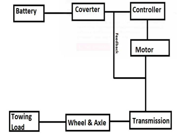
7. Design an electric powertrain with type of motor, it’s power rating, and energy requirement to fulfill aircraft towing application. Estimate the duty cycle range to control the aircraft speed from zero to highest. Make all required assumptions. Prepare a table of assumed parameters. Draw a block diagram of powertrain.
Assumptions :
1. Weight of the Aircraft 575000 kg
2. Weight of the Towing Tractor 50000 kg
3. Rolling Resistance Coecient of Aircraft 0.004
4. Rolling Resistance Coecient of Towing Tractor 0.001
5. The velocity of the Aircraft while Towing 8.33 m/s
6. Density of Air medium(rho) 1.225 kg/m^3
7. The Frontal area of the Aircraft 20 m^2
8. The Coecient of Drag of the Aircraft 0.026
9. Towing Tractor Gear ratio(G- for high torque output) 11
10. Towing Tractor tyre radus(r) 0.635 m
11. Operational time of the Towing for one cycle 0.33 Hour
12. The Battery Armature Voltage 350 V
13. The Battery Armature Current 350 A
14. The Motor Terminal Voltage for full power output 630 V @ motor terminals
15. Power converters used Bidirectional DC-DC Boost Converter
16. The maximum duty ratio for acieving full power 70%
Energy :
Assuming the operational time of the Towing Truck is around 20 minutes for one cycle
20 minutes = 0.33 hour
Energy(kwh) = power(kw)*Time(h) = 162.8*0.33
Energy(kwh) = 41.8 kwh
Therefore the battery must be able to store the energy 41.8 kwh and should deliver the energy throughout the run time in order for the motor to produce the 1.32 KNm of torque instantaneously. Thus the storage of energy in batteries with high performance Ultracapacitors are selected to fulll the required power deliver.
Motor Selection:
Here PMSM motor type is selected that has a power rating of 126.8kw and with the gear ratio and the transmission it should be able to deliver 1.32KNm of torque instantaneously.
The Battery Armature Voltage (V) = 350 V
The Battery Armature Current (A) = 350 A
Power Converter:
A boost converter (step-up converter) is a DC-to-DC power converter that steps up voltage (while stepping down current) from its input (supply) to its output (load).
The Electric Vehicle uses power from the battery source to drive the motor and then further to drive the wheels in order to move the vehicle. The speed and torque generated from the motor is very important to drive the vehicle as per the driver's desire. If we connect the battery directly to the motor the motor will spin with a speed and torque characteristics which will be based on the full power of the battery voltage. We do not require full power in all the driving conditions so we need to adopt a power controller between the bettery and the motor so that the motor speed may be controlled by the driver to drive the vehicle as desired.
For controlling the vehicle power we use the soft switching operation technique here. The amount of power can be controlled by changing the Duty Cycle value. Considering the losses we take 70% of the duty cycle to deliver the maximum power of the motor.
Motor Terminal Voltage = Armature Voltage * Duty Cycle = 900*0.7
With 70% Duty Cycle the voltage at motor terminals = 630V, Which gives the full power with all the gearings instantaneously. Thus by varying the Duty Cycle value the speed of the vehicle is controlled.
Block Diagram of Powertrain :