Project-1: Powertrain for aircraft in runways
objective:
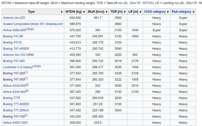
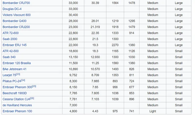
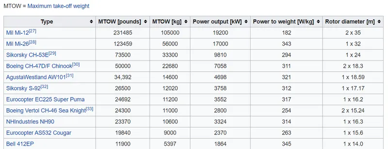
- Search and list out the total weight of various types of aircrafts.
- Is there any difference between ground speed and air speed?
- Why is it not recommended to use aircraft engine power to move it on the ground at Airport?
- How an aircraft is pushed to runway when its ready to take off?
- Learn about take-off power, tyre design, rolling resistance, tyre pressure, brake forces when landing.
- With necessary assumptions, calculate the force and power required to push / pull an aircraft by a towing vehicle.
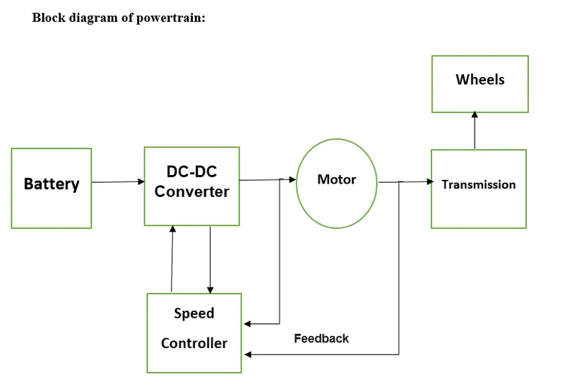
- Design an electric powertrain with type of motor, it’s power rating, and energy requirement to fulfill aircraft towing application. Estimate the duty cycle range to control the aircraft speed from zero to highest. Make all required assumptions. Prepare a table of assumed parameters. Draw a block diagram of powertrain.
Study 1.
1.Search and list out the total weight of various types of aircrafts.
Ans:
According to type of propulsion, Aircrafts are categorised as follows:
Unpowered aircraft:
Unpowered aircraft can remain airborne for a significant period of time without onboard propulsion. They can be classified as fixed-wing gliders, lighter-than-air, balloons and tethered kites.
Powered aircraft:
A powered aircraft is an aircraft that uses onboard propulsion with mechanical power generated by an aircraft engine of some kind.
Powered aircrafts are further categorised as follow:
Propeller Aircraft:
A propeller or airscrew comprises a set of small, wing-like aerofoil blades set around a central hub which spins on an axis aligned in the direction of travel. The blades are set at a pitch angle to the airflow, which may be fixed or variable, such that spinning the propeller creates aerodynamic lift, or thrust, in a forward direction.
Jet Aircrafts:
Airbreathing jet engines provide thrust by taking in air, compressing the air, injecting fuel into the hot compressed air mixture in a combustion chamber, the resulting accelerated exhaust ejects rearwards through a turbine which drives the compressor. The reaction against this acceleration provides the engine thrust.
Rotorcrafts:
Rotorcraft have spinning blades called a rotor which spins in the horizontal plane to provide lift. Forward thrust is usually obtained by angling the rotor disc slightly forward so that a proportion of its lift is directed backwards; these are called helicopters. Other rotorcraft are compound helicopters and autogyros, which sometimes use other means of propulsion, such as propellers and jets.
Rocket powered Aircrafts:
Rocket propulsion offers very high thrust for light weight and has no height limit, but suffers from high fuel consumption and the need to carry oxidant as well as propellant.
Design Weight limit:
Maximum design taxi weight (MDTW)
The maximum design taxi weight (also known as the maximum design ramp weight (MDRW)) is the maximum weight certificated for aircraft manoeuvring on the ground (taxiing or towing) as limited by aircraft strength and airworthiness requirements.
Maximum design taxi weight (MDTW)
The maximum design taxi weight (also known as the maximum design ramp weight (MDRW)) is the maximum weight certificated for aircraft manoeuvring on the ground (taxiing or towing) as limited by aircraft strength and airworthiness requirements.
Maximum design landing weight (MDLW)
The maximum certificated design weight at which the aircraft meets the appropriate landing certification requirements. It generally depends on the landing gear strength or the landing impact loads on certain parts of the wing structure.
The MDLW must not exceed the MDTOW.
Maximum design zero-fuel weight (MDZFW)
It is the maximum weight permitted before usable fuel and other specified usable fluids are loaded in specified sections of the airplane.
Minimum flight weight (MFW)
Minimum certificated weight for flight as limited by aircraft strength and airworthiness requirements.
Weight of various aircrafts is as follows:
Helicopters:
Study 2:
Is there any difference between ground speed and air speed?
Ans:
Yes, there is difference between ground speed and air speed.
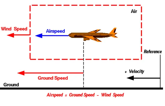
Ground speed is the horizontal speed of an aircraft relative to the Earth’s surface. It is vital for accurate navigation to the destination that the pilot has an estimate of the ground speed that will be achieved during a flight.
Airspeed is the speed of an aircraft relative to the air. Airspeed is the vector difference between ground speed and wind speed.
Study 3:
Why is it not recommended to use aircraft engine power to move it on the ground at Airport?
Ans:
Taxiing is the movement of an aircraft on the ground, under its own power, in contrast to towing or push-back where the aircraft is moved by a tug.
Although many aircraft are capable of moving themselves backwards on the ground using reverse thrust, the resulting jet blast or prop wash might cause damage to the terminal building or equipment. Engines close to the ground may also blow sand and debris forward and then suck them into the engine, causing damage to the engine. At low power settings, combustion aircraft engines operate at lower efficiency than at cruise power settings. A typical A320 spends an average of 3.5 hours a day taxiing, using 600 liters (160 U.S. gal) of fuel. A pushback is therefore the preferred method to move the aircraft away from the gate.
Study 4:
How an aircraft is pushed to runway when its ready to take off?
Ans:
Pushback is an airport procedure that results in an aircraft being pushed backwards away from an airport gate by external power, which is usually provided by pushback tractors or aviation tugs.
it is strange that external power is used in order to push an aircraft backwards but, although the majority of aircraft are able to move backwards, it may lead to avoidable damage being caused, either to the engine, other equipment being used during the procedure, or the terminal building itself. This is why pushback tractors and aircraft tugs are generally preferred to ensure that aircraft is safely moved from the gate.
The aircraft then moves under its own power along the taxiways. This means that following engine start at the gate, the thrust reversers are used to literally back the aircraft away from the gate. The aircraft then moves under its own power along the taxiways. This is called Taxiing
Study 5:
Learn about take-off power, tyre design, rolling resistance, tyre pressure, brake forces when landing.
Ans:
Take-off Power
Take-off is phase of flight in which aircraft leaves the ground and become airborne. Take-off power is the power used by aircraft from an engine to lift the aircraft from ground.
Tyre design:
Two types of tires are used in aircraft applications — bias-ply tires and radial tires.
Bias-ply tire construction
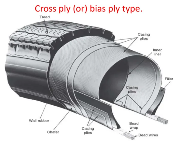
Bias-ply tires are popular choices for aircraft tires because of their durability and re-tradability. The tire construction consists of the following components:
Tread: The tread is made of rubber mixed with other additives to obtain the desired level of toughness, durability, and resistance to wear. The tread pattern is designed to aircraft operational requirements, with the ribbed tread design used widely due to its good traction under varying runway conditions.
Sidewall: The sidewall is a protective layer of rubber that covers the outer casing ply. It extends from the tread edge to the bead area.
Tread Reinforcing Ply:One or more layers of fabric that strengthens and stabilizes the tread area for high-speed operation. It also serves as a reference for the buffing process when tires are re-treaded.
Buff Line Cushion: The buff line cushion is made of rubber compound to enhance the adhesion between the tread reinforcing ply and the breakers or casing plies. It is of sufficient thickness to allow for the removal of the old tread when the tire is re-treaded.
Breakers: Breakers are reinforcing plies of rubber-coated fabric placed under the buff line cushion to protect casing plies and strengthen and stabilize the tread area.
Casing Plies: Alternate layers of rubber-coated fabric (running at opposite angles to one another) provide the strength of the tire.
Wire Beads: Hoops of high tensile strength steel wire that anchor the casing plies and provide a firm mounting surface on the wheel. The outer edge of the bead that fits against the wheel flange is called the bead heel. The inner bead edge is called the bead toe.
Apex Strip: A wedge of rubber affixed to the top of the bead bundle.
Flippers: Layers of rubberized fabric that help anchor the bead wires to the casing and improve the durability of the tire.
Ply Turnups: The casing plies are anchored by wrapping them around the wire beads, thus forming the ply turnups.
Chafer: A protective layer of rubber and/or fabric located between the casing plies and wheel to minimize chafing.
Liner: In tubeless tires, the liner is a layer of low permeability rubber that acts as a built-in tube and restricts gas from diffusing into the casing plies. In tube-type tires, a thinner liner is used to prevent tube chafing against the inside ply.
Radial-ply tire construction
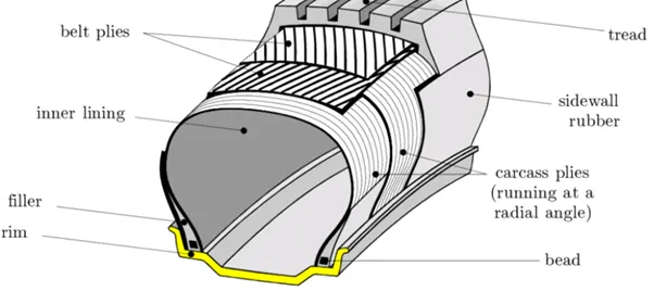
Overlay: A layer of reinforcing rubber coated fabric placed on top of the belts to aid in high speed operation.
Belt Plies: A composite structure that stiffens the tread area for increased landings. The belt plies increase the tire strength in the tread area.
Casing Plies: As in bias-ply tires, the casing plies are layers of rubber-coated fabric. However, unlike those in bias plies that run at opposite angles to one another, radial plies run radially from bead to bead.
Chippers: The chippers are layers of rubber-coated fabric applied at diagonal angles that improve the durability of the tire in the bead area.
Rolling resistance:
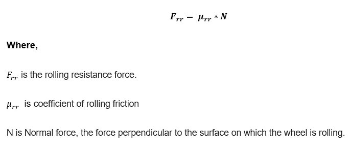
The force that resists the motion of a body rolling on a surface is called the rolling resistance or the rolling friction.
Tyre pressure:
Each of the twelve Boeing-777-300 ER main tires is inflated to 220 psi (15 bar; 1,500 kPa), weighs 120 kg (260 lb), has a diameter of 134 cm (53 in) and is changed every 300 cycles. Aircraft tires generally operate at high pressures, up to 200 psi(14 bar; 1,400 kPa) for airliners, and even higher for business jets. The main landing gear on the Concorde was typically inflated to 232 psi (16.0 bar), whilst its tail bumper gear tires were as high as 294 psi (20.3 bar). Aircraft tires are usually inflated with nitrogen to minimize expansion and contraction from extreme changes in ambient temperature and pressure experienced during flight.
Brake forces while landing:
Engine Power:
The most important action to achieve deceleration from a speed at which the engines are still producing forward motion is to select all thrust/power levers to the ground idle position promptly, and if available, continue the action through to the selection of reverse thrust or reverse propeller pitch. This is the first action to begin deceleration and must especially be achieved without delay when a high speed rejected take off is initiated. Thrust reversers and reverse propeller pitch are most effective at high speeds.
Mechanical Spoilers:
The mechanical deflection of parts of the wing upper surfaces and tail cone assembly can assist deceleration in two ways:
Directly, by increasing aerodynamic drag on the moving aircraft. This can be achieved by raising upper wing surface panels called ground spoilers or by operation of a tail cone ‘clamshell’ type air brake.
Indirectly by increasing the effective downward load on the landing gear and thereby increasing the efficiency of wheel braking.
Study 6:
With necessary assumptions, calculate the force and power required to push / pull an aircraft by a towing vehicle.
Ans:
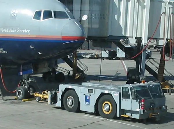
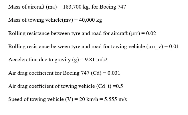
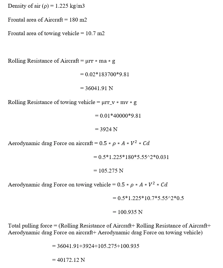
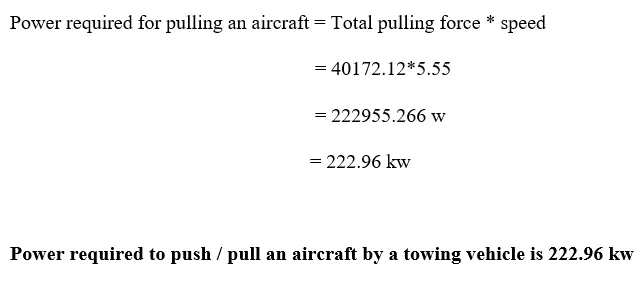
To move an aircraft with the help of towing truck, towing vehicle has to overcome the rolling resistance between its own wheels and runway plus rolling resistance between the wheels of aircraft and runway and air drag offered by the wind.
Study 7:
Design an electric powertrain with type of motor, it’s power rating, and energy requirement to fulfil aircraft towing application. Estimate the duty cycle range to control the aircraft speed from zero to highest. Make all required assumptions. Prepare a table of assumed parameters. Draw a block diagram of powertrain.
Ans:
Total traction force (Fte) = 40172.2 N
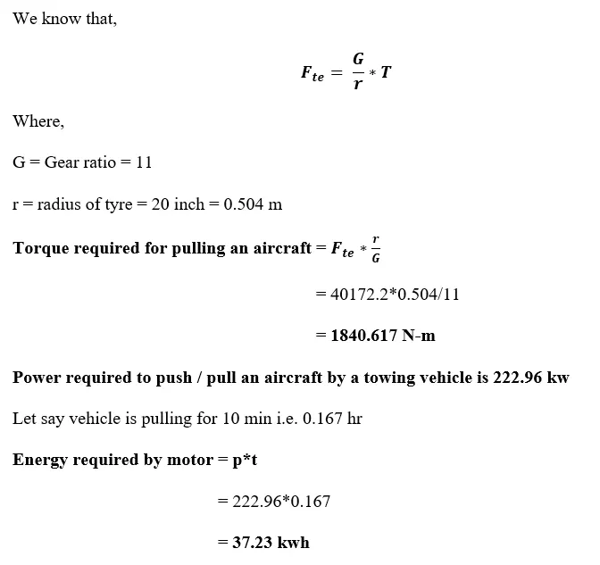
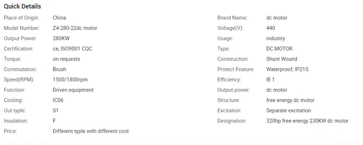
Motor Selection:
227 kw power rating brushless motor should be selected which can deliver the torque of 1.84 kN-m. Here we are selecting DC motor.
Battery Selection:
A 440 v DC supply is selected, A Battery should be able to store 37.23 kwh energy. To ensure continuous electric supply Super-Capacitors should be used.
Power Converter:
Boost converters:
A process that changes one DC voltage to a different DC voltage is called DC to DC conversion. A boost converter is a dc to dc converter with an output voltage greater than the source voltage. A boost converter is sometimes called a step-up converter since it "steps up" the source voltage. Since power (P=V*I) must be conserved, {displaystyle P=VI}the output current is lower than the source current. To deliver the rated power of 280 kW voltage supply should be 650 V.
Speed Controller:
Pulse-width modulation (PWM), is a method of reducing the average power delivered by an electrical signal, by effectively chopping it up into discrete parts. The average value of voltage (and current) fed to the load is controlled by turning the switch between supply and load on and off at a fast rate. The longer the switch is on compared to the off periods, the higher the total power supplied to the load.
Duty Cycle = Vout/Vin
= 440/650
= 0.6769
= 67.69 %