Project-1: Powertrain for aircraft in runways
Project-1: Powertrain for aircraft in runways
Part A:
- Search and list out the total weight of various types of aircrafts.
- Is there any difference between ground speed and air speed?
- Why is it not recommended to use aircraft engine power to move it on the ground at Airport?
- How an aircraft is pushed to runway when its ready to take off?
- Learn about take off power, tyre design, rolling resistance, tyre pressure, brake forces when landing.
Part B:
- A. With necessary assumptions, calculate the force and power required to push / pull an aircraft by a towing vehicle.
- Develop the model for the calculated force and power using Simulink.
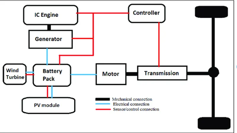
- A. Design an electric powertrain with type of motor, it’s power rating, and energy requirement to fulfill aircraft towing application in Simulink. Estimate the duty cycle range to control the aircraft speed from zero to highest. Make all required assumptions. Prepare a table of assumed parameters. Draw a block diagram of powertrain.
(Hint :DC7 Block)
- Also, Design the parameters in excel sheet
Answer: -
Part-A
Total weight of various types of aircrafts.
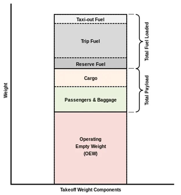
he maximum takeoff weight (MTOW) or maximum gross takeoff weight (MGTOW) or maximum takeoff mass (MTOM) of an aircraft is the maximum weight at which the pilot is allowed to attempt to take off, due to structural or other limits.
We can see the aircraft weight component is given,
Maximum design taxi weight (MDTW)
The maximum design taxi weight (also known as the maximum design ramp weight (MDRW)) is the maximum weight certificated for aircraft manoeuvring on the ground (taxiing or towing) as limited by aircraft strength and airworthiness requirements.
Maximum design takeoff weight (MDTOW)
Is the maximum certificated design weight when the brakes are released for takeoff and is the greatest weight for which compliance with the relevant structural and engineering requirements has been demonstrated by the manufacturer.
List of Aircrafts having maximum takeoff weight (MTOW) :
|
Type |
MTOW [kg] |
|
6,40,000 |
|
|
5,89,670 |
|
|
Airbus A380-800[1][2][3] |
5,75,000 |
|
4,47,700 |
|
|
4,43,613 |
|
|
4,12,770 |
|
|
4,05,060 |
|
|
3,96,900 |
|
|
Lockheed C-5 Galaxy[4][5][6] |
3,81,000 |
|
Boeing 747-200[7] |
3,77,840 |
|
Boeing 747-300[7] |
3,77,840 |
|
Airbus A340-500[8] |
3,71,950 |
|
Airbus A340-600[8] |
3,67,400 |
|
3,47,800 |
|
|
3,51,800 |
|
|
3,47,450 |
|
|
Boeing 747-100[7] |
3,40,200 |
|
3,08,000 |
|
|
2,99,370 |
|
|
2,97,550 |
|
|
Airbus A340-300[8][9] |
2,76,700 |
|
2,73,300 |
|
|
2,70,000 |
|
|
2,70,000 |
|
|
2,56,280 |
|
|
Boeing 787-9[10] |
2,54,000 |
|
Boeing 787-10[10] |
2,54,000 |
|
Airbus A340-200[8][11] |
2,53,500 |
|
2,51,000 |
|
|
2,50,000 |
|
|
Airbus A330-300[12][13] |
2,42,000 |
|
Airbus A330-200[12][13] |
2,42,000 |
|
2,31,300 |
|
|
Boeing 787-8[10] |
2,28,000 |
|
2,11,400 |
|
|
2,08,000 |
|
|
2,04,000 |
|
|
Airbus A300-600R[14] |
1,92,000 |
|
1,87,000 |
|
|
1,85,000 |
|
|
Airbus A300-600[14] |
1,63,000 |
|
1,59,000 |
|
|
Airbus A310-300[14] |
1,57,000 |
|
1,52,000 |
|
|
Boeing 707-320B[15] |
1,51,000 |
|
Boeing 707-320C[15] |
1,51,000 |
|
1,47,000 |
|
|
Airbus A310-200[14] |
1,42,000 |
|
1,41,000 |
|
|
1,40,000 |
|
|
1,25,000 |
|
|
1,24,000 |
|
|
Boeing 707-120B[15] |
1,17,000 |
|
1,16,000 |
|
|
Boeing 720B[16] |
1,06,000 |
|
Boeing 720[16] |
1,04,000 |
|
1,04,000 |
|
|
1,04,000 |
|
|
87,500 |
|
|
85,000 |
|
|
85,000 |
|
|
Boeing 727-200 Advanced[17] |
84,000 |
|
Airbus A321-100[18] |
83,000 |
|
79,000 |
|
|
Boeing 727-200[17] |
78,000 |
|
73,000 |
|
|
Boeing 727-100[17] |
72,500 |
|
Boeing 727-100C[17] |
72,500 |
|
71,000 |
|
|
70,700 |
|
|
70,000 |
|
|
Airbus A320-100[18] |
68,000 |
|
68,000 |
|
|
68,000 |
|
|
67,000 |
|
|
66,000 |
|
|
65,000 |
|
|
65,000 |
|
|
Airbus A319[18] |
64,000 |
|
63,000 |
|
|
60,000 |
|
|
59,000 |
|
|
Airbus A318[18] |
59,000 |
|
55,000 |
|
|
55,000 |
|
|
54,000 |
|
|
50,000 |
|
|
50,000 |
|
|
48,600 |
|
|
48,500 |
|
|
Embraer 190[19] |
48,000 |
|
46,000 |
|
|
46,000 |
|
|
44,000 |
|
|
42,000 |
|
|
39,000 |
|
|
Embraer 175[20] |
37,500 |
|
Bombardier CRJ900[21] |
36,500 |
|
Embraer 170[22] |
36,000 |
|
33,000 |
|
|
33,000 |
|
|
30,400 |
|
|
28,000 |
|
|
23,000 |
|
|
22,800 |
|
|
22,800 |
|
|
22,000 |
|
|
18,600 |
|
|
13,150 |
|
|
11,500 |
|
|
10,890 |
|
|
Learjet 75[23] |
9,752 |
|
Pilatus PC-24[24] |
8,300 |
|
Embraer Phenom 300[25] |
8,150 |
|
7,765 |
- Is there any difference between ground speed and air speed?
Airspeed is the speed at which an aircraft is moving relative to the air, in which an aircraft is flying. As such, it’s also the speed at which the air is flowing around the aircraft’s wings.
Similarly, Ground speed is the speed of an aircraft relative to the ground. It is horizontal rather than vertical i.e. if an aircraft is climbing completely vertically upwards, it would have a zero ground speed.
In other words, while airspeed is what determines whether there is enough airflow around an aircraft to make it fly, ground speed is what determines how fast an aircraft will get to its destination.
difference between ground speed and airspeed
-One of the most confusing concepts for young scientists is the relative velocity between objects. Aerodynamic forces are generated by an object moving through a fluid (liquid or gas).
-A fixed object in a static fluid does not generate aerodynamic forces. Hot air balloons "lift" because of buoyancy forces and some aircraft like the Harrier use thrust to "lift" the vehicle, but these are not examples of aerodynamic lift.
-To generate life, an object must move through the air, or air must move past the object. Aerodynamic lift depends on the square of the velocity between the object and the air. Now things get confusing because not only can the object be moved through the air, but the air itself can move.
-To properly define the relative velocity, it is necessary to pick a fixed reference point and measure velocities relative to the fixed point. The reference point is fixed to the ground in this slide, but it could just as easily be fixed to the aircraft itself.
-It is important to understand the relationships of wind speed to ground speed and airspeed.
- Why is it not recommended to use aircraft engine power to move it on the ground at Airport?
Although many aircraft are capable of moving in backward using reverse thrust, as result the jet blast or prop wash might cause damage to the terminal building or equipment. Engine close to ground may also blow sand and debris forward and then suck them into the engine, causing damage to the engine.
A pushback truck lifts the front wheel of the aircraft, their role in most airports is to move the aircraft away from the parking spot onto the taxiways, which is called towing.
For movement on the ground, the aircraft uses its own engine power, which is called taxing.
- How an aircraft is pushed to runway when its ready to take off?
When an aircraft is pushed to runway when its ready to take off, this process is called as Pushback. As Pilots do not have a clear view of the ground from the flight deck so they have to rely on towing equipment’s when needed to pushback. Aircraft can use its own engines to do so, but it is not recommended especially for large aircrafts as, their more powerful thrust capabilities can become exceedingly dangerous. Engine thrust can easily send any loose items airborne, turn the tiniest grains of dust into hazardous projectiles and create debris that can cause damage to multi-million-dollar engines. Additionally, aircraft engines consume a great deal of fuel and generate extreme noise that can be harmful to ground personnel.
So, the pilot will communicate with the pushback vehicle or tug driver to start the pushback. Steering is done by the pushback tug driver and not by the pilots. Once the aircraft is perfectly positioned and far from the terminal tow-in gate and other vehicles, the airport tug is disconnected and the aircraft can use its engines and steering to move to the runway for take-off.
- Learn about take-off power, tyre design, rolling resistance, tyre pressure, brake forces when landing
Take off power: Take-off is the phase of flight in which an aircraft goes through a transition from moving along the ground (taxiing) to flying in the air and the amount of power that an engine is generating for take-off, is the take-off power. Usually, the engines are run at full power during take-off. Following the taxi motion, the aircraft stops at the starting line of the runway. Before take-off, the engines, particularly piston engines, are routinely run up at high power to check for engine-related problems. This makes a considerable noise. When the pilot releases the brakes, the aircraft starts accelerating rapidly until the necessary speed for take-off is achieved and is depend upon air density, aircraft weight, and aircraft configuration (flap and/or slat position). Air density is affected by factors such as field elevation and air temperature.
Tyre design:
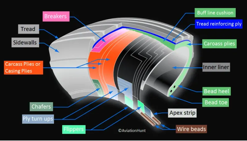
a)Tread: The tread is made of rubber mixed with other additives to obtain the desired level of toughness, durability, and resistance to wear. The tread pattern is designed to aircraft operational requirements, with the ribbed tread design used widely due to its good traction under varying runway conditions.
b) Sidewall: The sidewall is a protective layer of rubber that covers the outer casing ply. It extends from the tread edge to the bead area.
c) Tread Reinforcing Ply: One or more layers of fabric that strengthens and stabilizes the tread area for high-speed operation. It also serves as a reference for the buffing process when tires are retreated.
d) Buff Line Cushion: The buff line cushion is made of rubber compound to enhance the adhesion between the tread reinforcing ply and the breakers or casing plies. It is of sufficient thickness to allow for the removal of the old tread when the tire is retreated.
e) Breakers: Breakers are reinforcing plies of rubber-coated fabric placed under the buff line cushion to protect casing plies and strengthen and stabilize the tread area. They are considered an integral part of the casing construction.
f) Casing Plies: Alternate layers of rubber-coated fabric (running at opposite angles to one another) provide the strength of the tire.
g) Wire Beads: Hoops of high tensile strength steel wire that anchor the casing plies and provide a firm mounting surface on the wheel. The outer edge of the bead that fits against the wheel flange is called the bead heel. The inner bead edge is called the bead toe.
h)Apex Strip: A wedge of rubber affixed to the top of the bead bundle.
i)Flippers: Layers of rubberized fabric that help anchor the bead wires to the casing and improve the durability of the tire.
j)Ply Turnups: The casing plies are anchored by wrapping them around the wire beads, thus forming the ply turnups.
k)Chafer: A protective layer of rubber and/or fabric located between the casing plies and wheel to minimize chafing.
l)Liner: In tubeless tires, the liner is a layer of low permeability rubber that acts as a built-in tube and restricts gas from diffusing into the casing plies. In tube-type tires, a thinner liner is used to prevent tube chafing against the inside ply.
Rolling resistance: Rolling resistance is the opposing force a rolling body in motion experiences when it comes in contact with a surface. In other words, Tire rolling resistance is the energy that an aircraft needs to send to tires to maintain movement at a consistent speed over a surface. In other words, it is the effort required to keep a tire rolling. The main contributor to rolling resistance is the process known as hysteresis. Hysteresis is essentially the energy loss that occurs as a tire rolls through its footprint. The energy loss must be overcome by the engine, which results in wasted fuel.
Tyre pressure: -Aircraft tires generally operate at high pressures, up to 200 psi(14 bar; 1.400 kPa) for airliners, and even higher for business jets.
-The main landing gear on the Concorde was typically inflated to 232 psi (16.0 bar), whilst its tail bumper gear tires were as high as 294 psi (20.3 bar).
-Tests of airliner aircraft tires have shown that they can sustain pressures of the maximum of 800 psi (55 bar, 5.500 kPa) before bursting. During the tests, the tires have to be filled with water, to prevent the test room from being blown apart by the energy that would be released by a gas when the tire bursts Aircraft tires are usually inflated with nitrogen to minimize
-expansion and contraction from extreme changes in ambient temperature and pressure experienced during flight. Dry nitrogen Laye expands at the same rate as other dry atmospheric gases (normal air is about 80% nitrogen), but common compressed air sources may contain moisture, rate with temperature. which increases the expansion
Brake forces when landing:- All commercial aircraft have automatic brake systems. Just like a car, these systems also have an Anti-Lock braking system (ABS) that prevents the tires from sliding down a wet runway.
-The advantage of the automatic brake system is that the aircraft brakes comfortably at a constant deceleration. Passengers experienced a constant force that presses them into their seats.
-The brake system automatically applies the wheel brakes just enough to create a constant deceleration independent of the air resistance, spoilers and reversers. It is only in the last phase of brakes by pressing on both brake pedals. This deactivates the automatic brake system.
-Immediately after landing, the aircraft is still moving fast enough that aerodynamic devices are much more efficient than the brakes. The brake units are powered by the hydraulics system.
-An electrical signal is sent from the flight deck to hydraulic actuators near the main landing gear. Here, hydraulic fluid at 3.000 pounds per square inch is used to force the brake unit against the wheel, thus slowing it down.
Part = B
- A. With necessary assumptions, calculate the force and power required to push / pull an aircraft by a towing vehicle.
- Develop the model for the calculated force and power using Simulink.
We can Assume the data
Weight of the Aircraft =500000kg
Rolling Resistance Coefficient of an aircraft tire =0.005
Wight of the Towing Tractor=50000kg
Rolling Resistance Coefficient of Towing Vehicle =0.002
The Velocity of the Aircraft while Towing=18KMPH=5m/s
The density of Air medium=1.225 kg/m^3
The Frontal area of the Aircraft=20 m^2
The Coefficient of Drag of the Aircraft = 0.26
Towing Tractor Gear ratio(G- for high torque output) = 11
Towing Tractor tyre radius(r) = 0.5 m
The forces acting on the aircraft are
- i) Rolling Resistance
ii) Drag Force
i) Rolling Resistance for the Aircraft
Now. Rolling resistance be
Frr =c. mr. ag .. .. .. .. .. .. 1
Let.
Frr =Rolling resistance
c=coefficient of rolling resistance
mr=mass
ag =Acceleration of gravity
Substituting the values in the above formula
Resistance of the Aircraft gives us the Rolling
Fr(aircraft) = 0.005*(500000 kg)*(9.81 m/s^2)
Fr(aircraft)= 24.525 KN.
Rolling resistance of the aircraft Fr(aircraft)= 24.525 KN.
Rolling Resistance for the Towing Vehicle: -
Rolling resistance for the Towing Vehicle
Frr =c. mr. ag
Fr(towing)=0.002(50000 kg)(9.81 m/s^2)
Fr(towing)=0.981 KN.
Rolling resistance of the Towing vehicle Fr(towing)=0.981 KN.
- ii) Drag Force
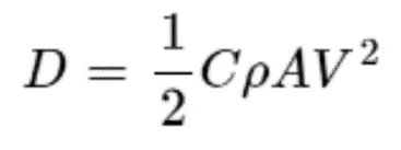
Where.
D=Drag force
C=Drag Coefficient
V=Velocity of Towing Vehicle
A=Frontal area
Now Substituting the assumed values in the above the Drag force of the Towing vehicle
Drag Force = 0.5* (0.26*1.225*20*5*5)
Drag Force = 0.079 KN
Drag force is 0.079625 KN
Now to get the total force to push the aircraft by the towing vehicle
we add the
=Rolling resistance of Aircraft + Rolling resistance of Towing Vehicle+ Drag Force
= 24.525 KN +0,981 KN+ 0.079625 KN
=25.585625 KN
Total force required for a towing vehicle to push the aircraft is=25.585625 KN=25585.625N
Power required to the towing vehicle to pull the aircraft
In this case,
Power=force*velocity
Power=25.585625*5.0
Power=127.928125 KW
- A. Design an electric powertrain with type of motor, it’s power rating, and energy requirement to fulfill aircraft towing application in Simulink. Estimate the duty cycle range to control the aircraft speed from zero to highest. Make all required assumptions. Prepare a table of assumed parameters. Draw a block diagram of powertrain.
(Hint :DC7 Block)
- Also, Design the parameters in excel sheet
Design electrical power train parameter
Weight of the Aircraft =500000kg
Rolling Resistance Coefficient of an aircraft tire =0.005
Wight of the Towing Tractor=50000kg
Rolling Resistance Coefficient of Towing Vehicle =0.002
The Velocity of the Aircraft while Towing=18KMPH=5m/s
The density of Air medium=1.225 kg/m^3
The Frontal area of the Aircraft=20 m^2
The Coefficient of Drag of the Aircraft = 0.26
Towing Tractor Gear ratio(G- for high torque output) = 11
Towing Tractor tyre radius(r) = 0.5 m
The total force required for a towing vehicle to push the aircraft is =25.585625 KN=25585.625N
Power required for the towing vehicle to pull the aircraft=127.928125KW=127928.125 W
Torque Required with the wheels of towing vehicle to push the aircraft
Torque=force *(radius/Gear ratio)
Torque= 25.585 *(0.5/11)
Torque=11629 KN-m
Therefore the Torque required the towing vehicle to push the aircraft =1.1629 KN-m
- i) Energy Requirements:
The Energy requirement for an EV similar to the Towing vehicle to Push/Pull the aircraft is calculated on the Basin of Time
Let
Energy =Power x Time taken by the towing vehicle to push-pull the aircraft
Energy=127.928 x 0.25
Energy =31.982 KWH
Therefore power required for one single towing is=31.982 KWh
Therefore, the battery must store the energy 31.982 KWH and deliver the energy throughout the run time for the motor to produce the 1.1629 KN-m of torque. Thus the storage of energy in batteries with high-performance Ultracapacitors are selected to fulfil the required power delivery.
Motor Selection:
Here we have selected a Permanent-Magnet Synchronous Motor (PMSM) type that has a power rating of 127.928 kw and with the gear ratio and the transmission, it should be able to deliver 1.1629 KN-m of torque instantaneously.
Duty Cycle:
Here in this case the Duty cycle of the electric power train is calculated by the output power by the input power By this, we get the efficiency of the duty cycle.
Duty Cycle = Output Power /Input Power
We know that.
Output Power=127.92 kW
Input Power =Rated Motor Power / Motor Efficiency-
Input Power =150/0.9
Input Power=166.666kW
Then
Duty Cycle =127.92/166.666
Duty Cycle =0.76
Duty Cycle =76%
Therefore the Efficiency of the Duty cycle that we get for this electric power train is=0 to 76%
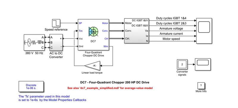
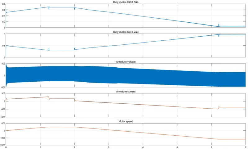
The example shown the DC7 four-quadrant chopper DC drive during speed regulation
The 200 HP DC motor is separately excited with a constant 150 VDC field voltage source. The armature voltage is provided by an IGBT converter controlled by two Pl regulators
The converter is fed by a 515 V DC bus obtained by rectifying a 380 V AC 50 Hz voltage source. To limit the DC bus voltage during dynamic braking mode, a braking chopper has been added between the diode rectifier and the DC7 block
The first regulator is a speed regulator, followed by a current regulator. The speed regulator outputs the armature current reference (in .p.u) used by the current controller to obtain the electromagnetic torque needed to reach the desired speed.
The speed reference change rate follows acceleration and deceleration ramps to avoid sudden reference changes that could cause armature over-current and destabilize the system
The current regulator controls the armature current by computing the appropriate duty ratios of the 5 kHz pulses of the four IGBT devices (Pulse Width Modulation). For proper system behaviour, the instantaneous pulse values of IGBT devices land, 4 are opposite to those of IGBT devices 2 and 3. This generates the average armature voltage needed to obtain the desired armature current
To limit the amplitude of the current oscillations, a smoothing inductance is placed in scenes with the armature circuit.
Output