Project-1: Powertrain for aircraft in runways
part A )
ANS :
Weight is a major factor in airplane construction and operation, and it demands respect from all pilots and particular diligence by all maintenance personnel. Excessive weight reduces the efficiency of an aircraft and the available safety margin if an emergency condition should arise. The total weight is the maximum take-off weight. It is the maximum mass at which the aircraft is certified for take-off due to structural or other limits.
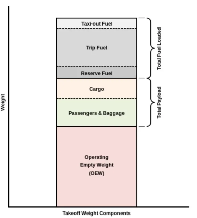
MTOW = Maximum take-off weight, MLW = Maximum landing weight, TOR = Take-off run, LR Landing run
Maximum Takeoff Weight:
The maximum weight limits for an aircraft to begin its takeo roll is called the max takeoff weight.
Maximum Landing Weight:
The maximum landing weight is, as you might imagine, the maximum aircraft weight limit approved for an aircraft to land. Landing weight can cause structural damage.
| Type | MTOW [kg] |
|---|---|
| Antonov An-225 | 640,000 |
| Scaled Composites Model 351 Stratolaunch | 589,670 |
| Airbus A380-800 | 575,000 |
| Boeing 747-8F | 447,700 |
| Boeing 747-8 | 443,613 |
| Boeing 747-400ER | 412,770 |
| Douglas DC-8-32 | 140,000 |
| Tupolev Tu-154M | 104,000 |
| Bombardier Q400 | 28,000 |
| ATR 42-500 | 18,600 |
| BAe Jetstream 41 | 10,890 |
| Learjet 75 | 9,752 |
| Cessna Citation CJ4 | 7,761 |
MTOW[kg]: Maximum Take off weight in kg
#2. Is there any difference between ground speed and air speed?
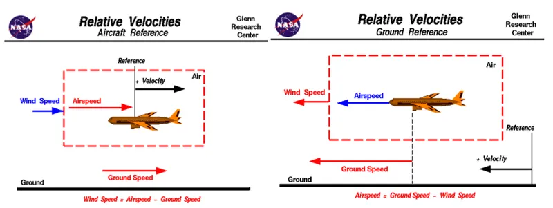
Ground speed
Ground speed is the horizontal speed of an aircraft relative to the ground. An aircraft heading vertically would have a ground speed of zero.
Ground speed can be determined by the vector sum of the aircraft's true airspeed and the current wind speed and direction; a headwind subtracts from the ground speed, while a tailwind adds to it. Winds at other angles to the heading will have components of either headwind or tailwind as well as a crosswind component.
Wind Speed
For a reference point picked on the ground, the air moves relative to the reference point at the wind speed. A positive velocity is defined to be in the direction of the aircraft's motion. We are neglecting cross winds, which occur perpendicular to the flight path but parallel to the ground, and updrafts and downdrafts, which occur perpendicular to the ground.
Airspeed
The important quantity in the generation of lift is the relative velocity between the object and the air, which is called the airspeed. Airspeed cannot be directly measured from a ground position, but must be computed from the ground speed and the wind speed. Airspeed is the vector difference between the ground speed and the wind speed.
Airspeed Ground Speed - Wind Speed
- The aircraft usually operates on land as well as in air and so we need to study their speed differences in-ground and in air
- The ground speed and the airspeed usually change based on the wind component.
- If we consider that there is no wind component then, ground speed = airspeed
- If the wind is blowing in the tail direction of the aircraft then, (airspeed > ground speed) so, airspeed = ground speed+ wind component.
- If the wind is blowing in the head direction of the aircraft then, (airspeed < ground speed)so, airspeed ground speed - wind component.
- Also, gravity plays a major role in increasing the aircraft's speed while it is descending.
- Here wind speed is the vector difference between ground and airspeed. On a particular day, the wind speed may be zero and it is equal to the ground speed.
- If the measured airspeed is greater than the observed ground speed the wind speed becomes positive.
For Visualisation purporse by NASA:
https://www.grc.nasa.gov/www/k-12/airplane/Animation/airrel/anrelg.html
#3. Why is it not recommended to use aircraft engine power to move it on the ground at Airport?
Aircraft can move using their own engine power all the time on the airport apron and taxiways under their own power to go towards runways and after landing taxi to their assigned gate. But the thrust produced resulting jet blast might cause damage to the terminal building or equipment. Engines close to the ground may also blow sand and debris forward and then suck them into the engine, causing damage to the engine. A pushback is therefore the preferred method to move the aircraft away from the gate. And also it can reduce the cost for fuel. Taxiing can save money.
- Effectively a loss of control can happen, especially during high power engine running. Damage can occur to the aircraft itself, other aircraft nearby or to airsidestructures.
- There is a risk of injury to ground support personnel who may be in relatively close proximity to the aircraft.
- It is easier for truck driver to see the surroundings better than the pilot sitting in the cockpit with limited window. The pushback driver knows the airport better than the pilot.
- It also saves fuel virgin Atlantic hadproposed a new system in which pushback truck will move the aircraft all the way to runway to save fuel and reduce impact of environment.
- The plane engines are very loud. When more than one plane will add up their sound, than it will not be pleasent for passangers and others near airport.
#4. How an aircraft is pushed to runway when its ready to take off?
Taxiing
Taxiing is the movement of an aircraft on the ground, under its own power, in contrast to towing or push-back where the aircraft is moved by a tug. The aircraft usually moves on wheels, but the term also includes aircraft with skis or floats . An airplane uses taxiways to taxi from one place on an airport to another; for example, when moving from a hangar to the runway.
Towing:
Movement of large aircraft about the airport, flight line, and hangar is usually accomplished by towing with a tow tractor. In the case of small aircraft, some moving is accomplished by hand pushing on the correct areas of the aircraft. Aircraft may also be taxied about the flight line but usually only by certain qualified personnel.
Towing aircraft can be a hazardous operation, causing damage to the aircraft and injury to personnel, if done recklessly or carelessly. This article outline the general procedure for towing aircraft. However, specific instructions for each model of aircraft are detailed in the manufacturer's maintenance instructions and are to be followed in all instances.
#5. Learn about take off power, tyre design, rolling resistance, tyre pressure, brake forces when landing.
Take off power:
Take off power can be predicted using a simple measure of the acceleration of the aircraft along the runway based on force equilibrium.
The forces involved will be.
T is Thrust of propulsion system pushing aircraft along the runway.
D is Aerodynamic Drag of vehicle resisting the aircraft motion.
F is Rolling resistance friction due to the contact of wheels or skids on the ground.
During the take-off run, the imbalance in these forces will produce an acceleration along the runway.
m*(dv/dt)=T-D-F
where, dv/dt is the acceleration along the runway and m is the mass of the vehicle.
The procedure for take-off will be that the vehicle will accelerate until it reaches a safe initial flying speed. The pilot can then rotate the vehicle to an attitude to produce a climb lift and it will ascend from the ground. The determination of this safe flying speed or rotation speed. V, is a critical factor in determining take-off performance. Take-off rules vary slightly depending on the aircraft category.
For Small commuter aircraft
V= 1.1*VSTALL
or
V=1.05*V Control
where S-Runway length
Take Off power = force*displacement
Tyre Design:
Designing aircraft tires is a very intense undertaking The tyre is designed to withstand heavy loads while landing, take off, taxing, and parking. The number of wheels required for aircraft increases with the weight of the aircraft, as the weight of the aeroplane needs to be distributed more evenly. Aircraft tyre generates more heat during landing Aircraft drags the wheel until they match the rotational velocity of wheels. Due to this heat generates. Aircraft's tread pattern is designed to facilitate stability in high crosswind conditions, to channel water away to prevent hydroplaning and for braking effect.
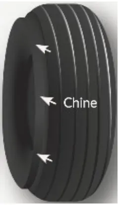
Construction of tyre:
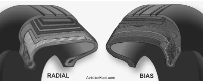
Radial Tyre: It has fibre strands of the ply fabric oriented at 90° to the direction of rotation and the tyre sidewall. This restricts flexibility bidirectional and the flexibility of the sidewall while it strengthens the tyre to carry heavy loads. Due to their unique construction most radial tyres are resistant to penetration ad cuts. Due to stiffer tread they distribute weight evenly. Thus provide greater traction. Radial tyres have an advantage in term of reducing the heat better.
Bias-ply Tyre: It has the fabric bias oriented with and across the direction of rotation and the sidewall. Since fabric can stretchon the bias, the tyre is flexible and can absorb loads. Tyre strength is obtained by adding plies. It is cut resistant is sidewall area. These tyres do not offer as much smoothness in terms of riding quality.
Rolling Resistance:
Rolling resistance is the force resisting the motion when a body (such as ball, tyre or wheel) rolls on a surface. Rolling resistance can be seen in the aircraft when the aircraft takes-off from the runway & while landing at the runway with the help of their wheels.
Rolling resistance can be expressed as
Where
m is mass (kg)
g is acceleration due to gravity = 9.81m/s^2
Tyre pressure:
Aircraft tyres operate at such high extremes of pressure, load, and speed, their care and service is critically important. The most important action an operator can take to prevent tyre-related events is to maintain proper tire inflation pressure. Failure to keep aircraft tires properly inflated can lead to very serious consequences. One relatively easy way to help avoid those consequences is to check tire pressures regularly and service them as necessary. Following these three actions is a good way to make sure you get the most value out of your tires and contribute to the safe operation of your aircraft.
Aircraft tires are usually inflated with nitrogen to minimize expansion and contraction from extreme changes in ambient temperature and pressure experienced during flight. Dry nitrogen expands at the same rate as other dry atmospheric gases (normal air is about 80% nitrogen). but common compressed air sources may contain moisture, which increases the expansion rate with temperature.
Also, the use of an inert gas for tire inflation eliminates the possibility of tire explosion.
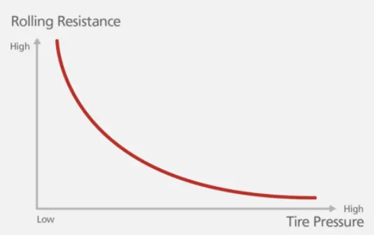
Relation to Rolling Resistance and Tire Pressure:
Rolling resistance and Tire pressure are inversly proportional.
Braking Forces During Landing:
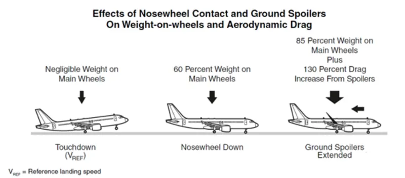
Following braking devices are used to decelerate the aircraft -
1. Spoilers.
2. Wheel Brakes (Including Anti-Skid systems & Auto-Brake systems).
3. Reverse Thrust
Spoilers:
The mechanical deflection of parts of the wing upper surface by increasing aerodynamic drag on the moving aircraft. This can be achieved by raising upper wing surface panels called ground spoilers or by operation of a tail cone 'clamshell' type air brake and also by increasing the effective downward load on the landing gear and thereby increasing the efficiency of wheel braking
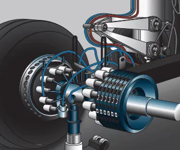
Wheel Brakes:
To be effective, braking action at any speed depends upon sufficient friction existing between the tires and the runway surface achieved through freely rotating wheels.
Anti skid system:
When landing on slippery runways, there's a chance that the wheels may start to skid as the brakes are applied. To stop this from happening and to maintain maximum effective braking, each wheel has anti-skid protection.
Using a variety of sources to determine the aircraft speed, the brake units know how fast the wheels should be spinning. If that speed drops significantly, it's because the current brake pressure on that wheel is too great and the wheel is just skidding over the surface.
In this situation, the anti-skid system automatically reduces the braking on that wheel to a point where the skid stops before reapplying the pressure.
Reverse Thrust:
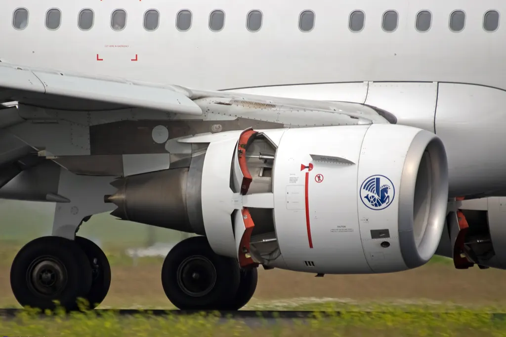
Thrust reversers provide a deceleration force that is independent of runway condition. Thrust reverser efficiency is higher at high airspeed therefore. Treversers must be selected as early as possible after touchdown.
Thrust reversers should be returned after reverse idle at low airspeed to prevent engine stall or foreign object damage.
#6. A. With necessary assumptions, calculate the force and power required to push / pull an aircraft by a towing vehicle.
B. Develop the model for the calculated force and power using Simulink.
A. With necessary assumptions, calculate the force and power required to push / pull an aircraft by a towing vehicle.
Considering:
Total mass of ther aircraft (including payload) for airbus a380 = 575,000kg.
Mass of the push back: 1000kg (assumed)
Rolling Resistance (Frr):
Coefficient of rolling resistance (Crr) = 0.002 (on tarmac)
Rolling resistance force is given by
For the aircraft:
For the Towing Vehicle:
As the towing vehicle resistance is so less compared to the Aircraft because this is a heavy aircraft these can be neglected
Aerodynamic resistnace (Far):
Drag coeffcient(Cd): 0.025
Air Density (
Frontal Area (A): 150m^2.
Velocity (v) = 14.5kmph or 4m/s
As the vehicle and Plane is moving at very low speed Aerodynamic resistance can be neglected
Hill Climb Resistnace:
Runways are constructed flat so Gradient resistance/ hill climb force is neglected.
Total Resistance:
Power Required:
The min power required by the tow vehicle is 45.26kW to taxi a heavy air craft at 4m/s.
B. Develop the model for the calculated force and power using Simulink.
Simulink Model:
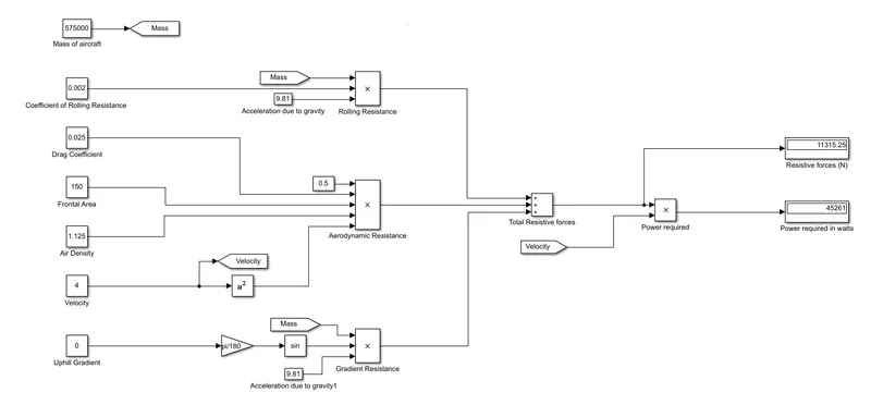
- constant blocks are used to feed the parameters such as mass, coefficients and other parameters
- using product block the resistive forces are calculated.
- using sum block, total resistive forces can be calculated.
- the outputs are visualised using display blocks.
#7. A. Design an electric powertrain with type of motor, it’s power rating, and energy requirement to fulfill aircraft towing application in Simulink. Estimate the duty cycle range to control the aircraft speed from zero to highest. Make all required assumptions. Prepare a table of assumed parameters. Draw a block diagram of powertrain.
B. Also, Design the parameters in excel sheet.
A. Design an electric powertrain with type of motor, it’s power rating, and energy requirement to fulfill aircraft towing application in Simulink. Estimate the duty cycle range to control the aircraft speed from zero to highest. Make all required assumptions. Prepare a table of assumed parameters. Draw a block diagram of powertrain.
Estimation of Duty Cycle:
Based on the calculation done in study 6
The Power Required for towing of the aircraft is 45.26kW.
Motor Considred for the drive train is REB 90

Technical Data:
| Type | Voltage | Continuous / Peak power | Working rotation | Max torque | Weight | Cooling |
| REB 90 | 400–800 V | 60–70 kW / 80 kW | 1 500–4 000 rpm | 300 Nm | 22 000 g |
Air / Hybrid (air + fluid) |
Considering 60kW as continuous power, so the voltage will be 400V
Battery power is considred to be 550v
Duty cycle is given by
where Vo is motor required voltage
Vb is battery voltage.
As there will be losses due to the resistance of FET and Inductance.
Correction factor is considred to be 90%
As there is 10% loss, the voltafge demanded by the motor should be 10% more than required
so the voltage demand should be around 440V from the battery.
| Assumed Parameters | ||
| Mass of aircraft | 575000 | kg |
| Mass of the push back truck | 1000 | kg |
| Coefficient of Rolling Resistance | 0.002 | |
| Drag Coefficient | 0.025 | |
| Air density | 1.125 | kg/m^3 |
| Frontal Area | 150 | m^2 |
| Velocity | 4 | m/s |
| Uphill gradient | 0 | deg |
| Battery Voltage | 550 | V |
| Correction Factor | 0.8 | |
Block Diagram:
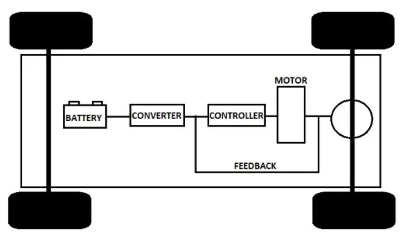
Simulink Model:
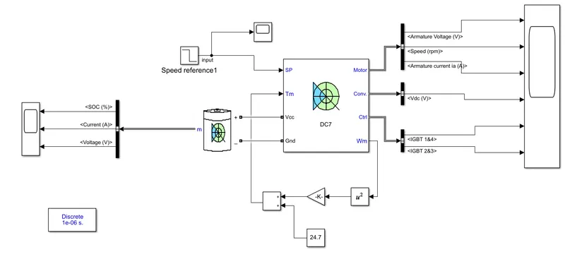
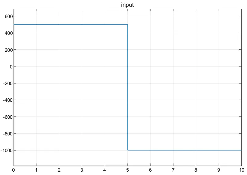
Input:
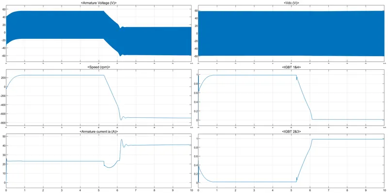
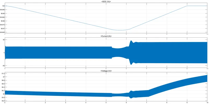
Output:
From the motor:
From the Battery:
Part B)
ANS :
Difference Between Ground Speed and Air Speed
Ground Speed>> The ground speed is how fast an airplane is traveling, relative to a fixed point on the ground. It is the speed of how fast an airplane's shadow would move across the land. If there's a strong wind pushing an aircraft, that's reflected in the ground speed.
Air Speed>> Airspeed is how fast an airplane is really flying strictly under its own power, which is the actual velocity of the aircraft.
| GROUND SPEED | AIR SPEED |
| 1. Ground speed is the speed of the aeroplane relative to the earth surface. |
1. Air speed is the speed of aeroplane relative to the air it is flying in. |
| 2. Ground speed determines how fast an aircraft will get to its destination. |
2. Air speed determines whether there is enough airflow around an aircraft to make it fly. |
| 3. Ground speed is the sum of air speed and wind speed. |
3. Air speed is independent of ground speed. |
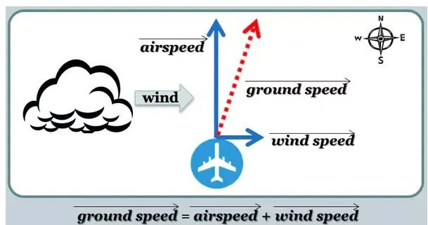 Fig- Ground Speed
In calculation of Ground speed and Air speed , the wind speed is the main factor. Depending on the direction and magnitude of Wind speed the relative ground speed and Air speed is calculated.
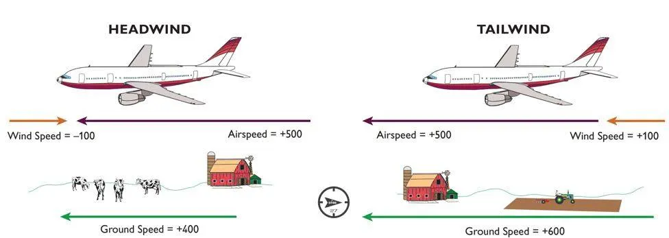 Fig- 1 Fig- 2
For Example- If Air speed of an aircraft is 500km/h, where as the wind speed is 100km/h in the same direction of air speed. Then the ground speed will be (500+100)= 600km/h, which is explained in Fig-2. But if the wind speed of 100km/h is in the opposite direction of air speed , then the ground speed will be (500-100)= 400km/h, which is explianed above in Fig-1.
STUDY 3: Not Recommended to Use Aircraft Engine Power to Move It on The Ground at Airport
For movement on the ground the aircraft uses it own engine power, which is called taxing.
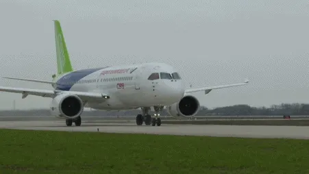
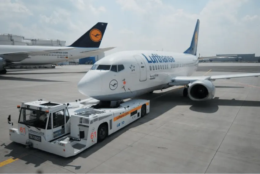
Although many aircrafts are capable of moving in backward using reverse thrust, as result the jet blast or prop wash might cause damage to the terminal building or equipment. Engine close to ground may also blow sand and debris forward and then suck them into the engine, causing damage to the engine. Therefore there are pushback trucks in the airport. A pushback truck lifts the front weel of the aircraft, their role in most airports is to move the aircraft away from the parking spot on to the taxiways, which is called towing.
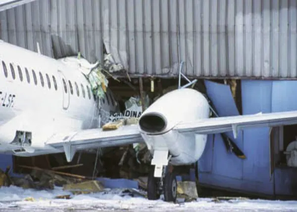
Unwanted consequences mainly arising from the unintended movement of the aircraft during engine running.
i) Effectively a loss of control can happen, especially during high power engine running. Damage can occur to the aircraft itself, other aircraft nearby or to airside structures. ii) There is a risk of injury to ground support personnel who may be in relatively close proximity to the aircraft. iii) It is easier for truck driver to see the surroundings better than the pilot sitting in the cockpit with limited window. The pushback driver knows the airport better than the pilot. iv) It also saves fuel. virgin Atlantic had proposed a new system in which pushback truck will move the aircraft all the way to runway to save fuel and reduce impact of environment. v) The plane engines are very loud. When more than one plane will add up their sound, than it will not be pleasent for passangers and others near airport.
STUDY 4: Pushing Aircraft to Runway When Its Ready to Take Off
TOWING>> In the parking areas, where taxing the aircraft is not practical or is unsafe, such as moving aircraft in and out of mainteance hangars, or moving aircraft that are not under their own power or moving backward, then towing of aircraft is performed using the power of a specialized ground vehicle attached to or supporting the nose landing gear. The traditional method of allowing the ground vehicle to move an aircraft is to attach it to the aircraft nose landing gear by means of towbar.
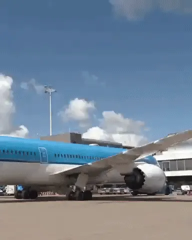
As the pilot can't see what is behind the aircraft, steering is done by pushback tractor driver and depending on the aircraft type and airline procedure, a bypass pin may be temporarily installed into the nose gear to disconnect it from the aircraft's normal steering mechanism. Once the towing is completed, the towbar is disconnected and the aircraft can taxiing forward under its own power.
TAXIING>> Taxiing is the movement of an aircraft on the ground under its own power while on the suface. The aircraft always moves following the yellow lines, to avoid collision with the surrounding buildings, vehicle or other aircrafts. The taxiing motion has a speed limit. Before making turn the pilot reduces speed further to prevent tire skids just like other vehicles. The reason for taxing is to reach the vehicle into runway or from runway to terminal.
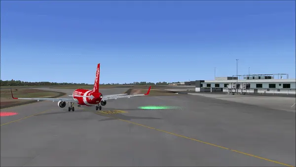
Following the taxiway aircraft reaches the runway. Takeoff is the phase of flight in which an aircraft goes through a transition from moving along the ground (taxiing) to flying in the air, usually starting on a runway. Usually the engines are run at full power during takeoff. Following the taxi motion, the aircraft stops at the starting line of the runway. Before takeoff, the engines, particularly piston engines, are routinely run up at high power to check for engine-related problems. This makes a considerable noise. When the pilot releases the brakes, the aircraft starts accelerating rapidly until the necessary speed for take-off is achieved.
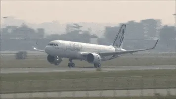 The takeoff speed required varies with air density, aircraft weight, and aircraft configuration (flap and/or slat position, as applicable). Air density is affected by factors such as field elevation and air temperature.
STUDY 5: About Take Off Power, Tyre Design, Rolling Resistance, Tyre Pressure, Brake Forces When Landing
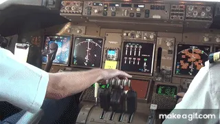
(i)Take Off Power>> Takeoff is the phase of flight in which an aircraft leaves the ground and becomes airborne. For aircraft that take off horizontally, this usually involves starting with a transition and moving along the ground on a runway. For light weight aircraft, usually full power is used during takeoff. Large transport catagory (airliner) aircraft may use a reduced power for takeoff, where less than full power is applied in order to prolong engine life, reduce maintenance costs and reduce noise emissions. In some cases, the power used can then be increased to increase the performance. Before takeoff, the engines, particularly piston engines are routinely run up at high power to check for engine-related problems.
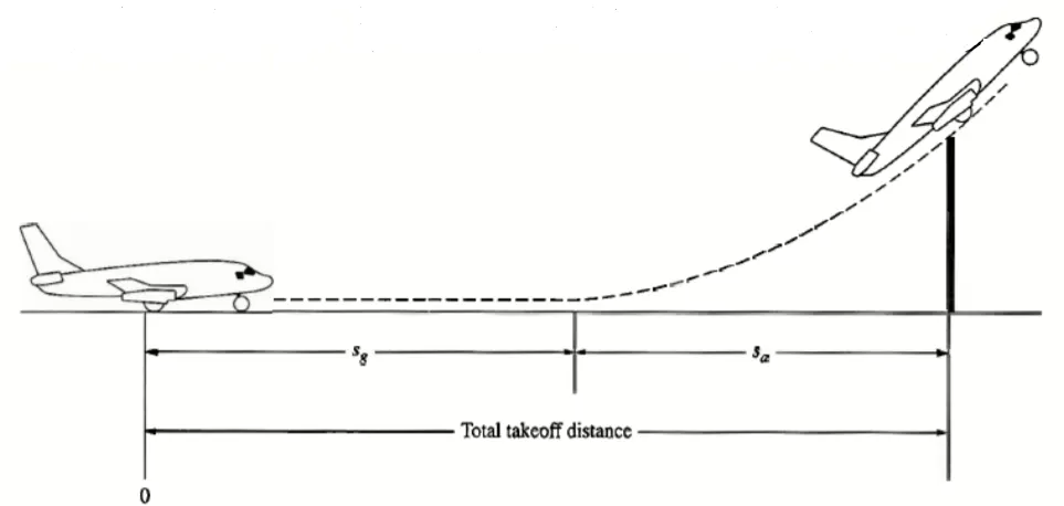 An airplane is motionless at the starting of a runway. This is denoted by location O. The pilot releases the brakes and pushes the throttle to maximum takeoff power, and the airplane accelerates down the runway. At some distance from its starting point, the airplane lifts into the air. The distance the airplane cover along the runway before it lifts into the air is called the ground roll (sg). The total takeoff distance also includes the extra distance covered over the ground after the airplane is airborne but before it clears an obstacle of 50 ft for military aircraft and 35 ft for commercial aircraft. This is denoted by sa. The sum of sg and sa is the total takeoff distance.
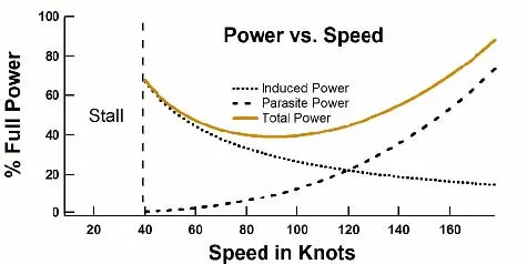 Figure bove shows the "power curves" for induced power, parasite power, and total power (the sum of induced power and parasite power). Again, the induced power goes as 1/speed and the parasite power goes as the speed . At low speed the power requirements of flight are dominated by the induced power. The slower one flies the less air is diverted and thus the angle of attack must be increased to increase the vertical velocity of that air. Pilots practice flying on the "backside of the power curve" so that they recognize that the angle of attack and the power required to stay in the air at very low speeds are considerable.
(ii)Tyre Design>> An aircraft tire is designed to withstand extremely heavy loads for short duration of time. The number of tires required for aircraft increases with the weight of the aircraft, as the weight of the airplane needs to be distributed more evenly. For example -A Boeing 737NG & 737MAX uses 6 wheels, Boeing 787 uses 10 wheels, Boeing 777 uses 14 wheels and Airbus A380 uses 22 wheels.
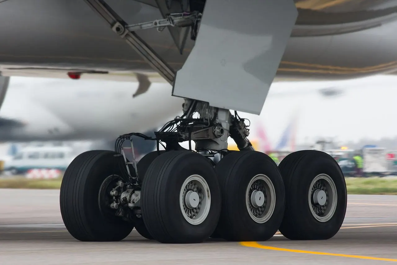 Fig- Tires on the wheels of a bogie on a Boeing 777
Aircraft tires also include fusible plugs (which are assembled on the inside of the wheels), designed to melt at a certain temperature. Tires often overheat if maximum braking is applied during an aborted takeoff or an emergency landing. The fuses provide a safer failure mode that prevents tire explosions by deflating in a controlled manner, thus minimizing damage to aircraft and objects in the surrounding environment.
Designing aircraft tires is a very intense undertaking. Carcass plies are used to form the tire. They are sometimes called casing plies. An aircraft tyre is constructed for the purpose it serves.
(i)They support the weight of an aircraft while it is on the ground.
(ii)It also provides the necessary traction for braking and stopping of an aeroplane.
(iii)Tyre also helps to absorb the shock of landing and provide cushioning the roughness of takeoff, roll-out, and taxi operations.
Once an aircraft manufacturer goes to the tire manufacturer with the size and weight requirements, the tire manufacturer begins the process of designing a tire that meets the needs of the aircraft manufacturer as well as all regulatory requirements — including foreign regulations in many cases. Engineers are challenged with designing tires with cool running, heat-resistant materials while simultaneously exceeding tire service requirements.
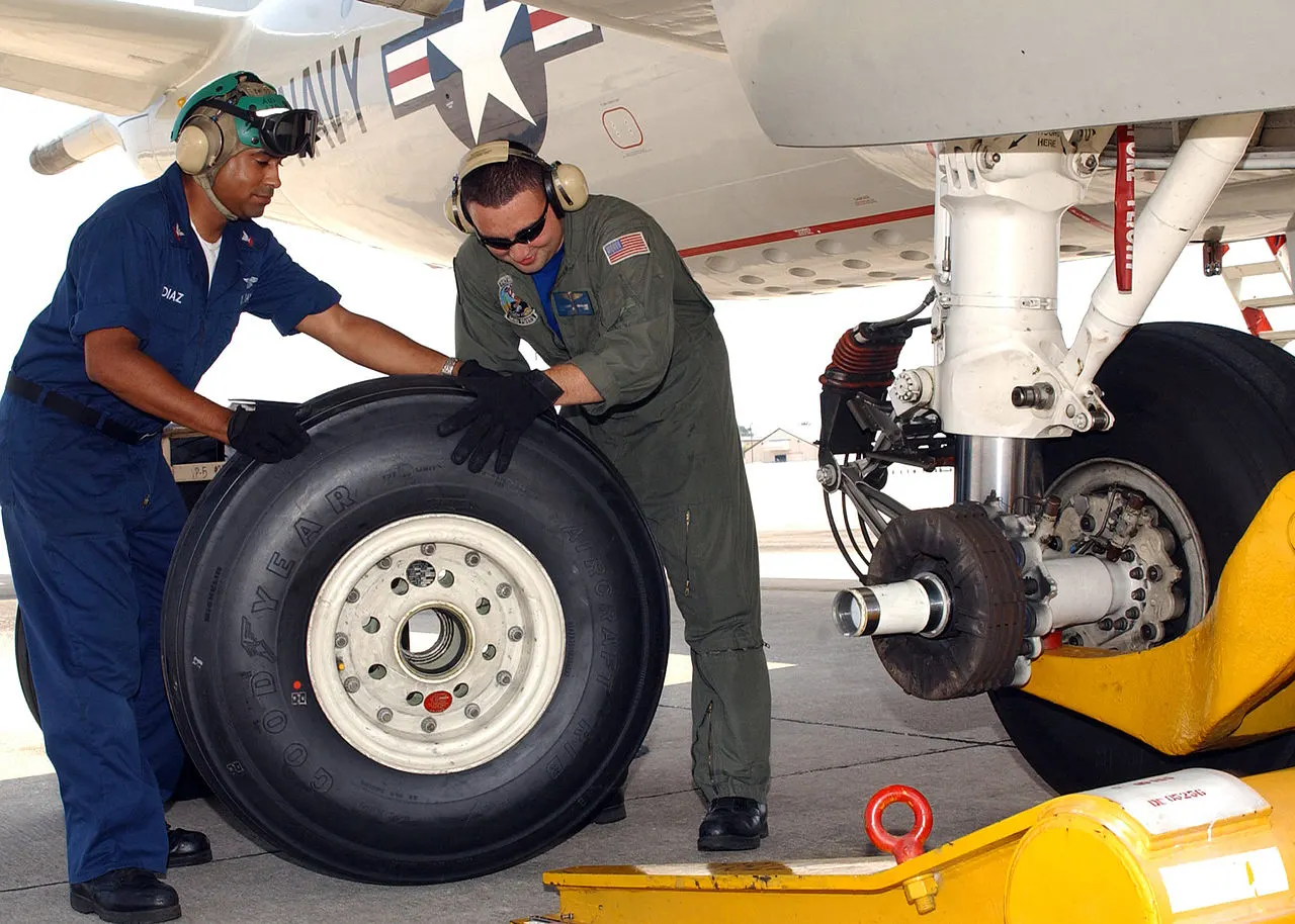 Fig- Changing a wheel on a Lockheed P-3 Orion aircraft
Two types of tires are used in aircraft applications — bias-ply tires and radial tires. Although both types of tires share some similarities in design, there are difference between a radial tyre and bias (cross-ply) tyre is the lay of the plies within the tyre carcass. The remainder of the tyre is very similar in construction in both.
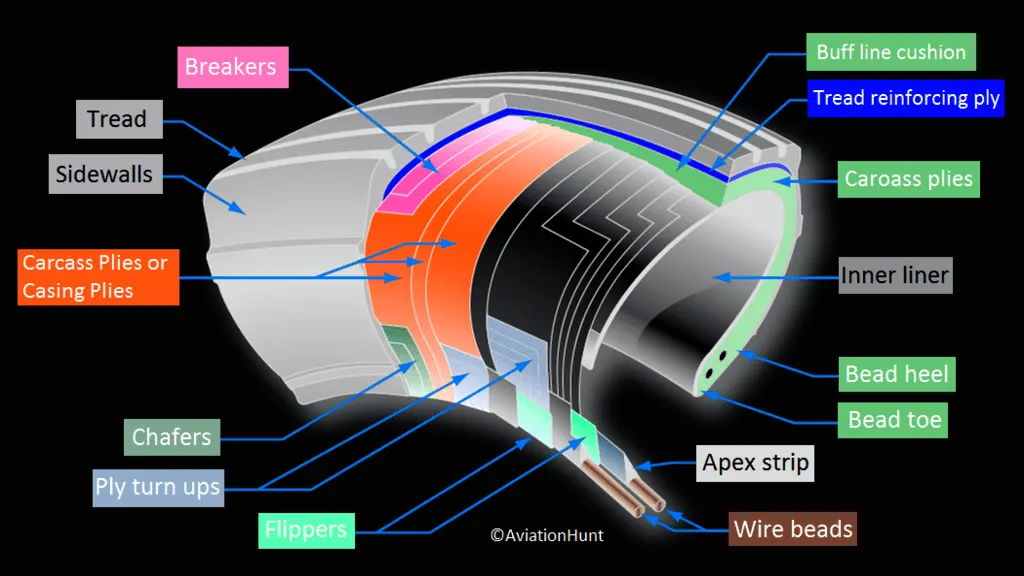 Fig- Design of Aircraft Tyre
Breakers: Breakers are reinforcing plies of rubber-coated fabric placed under the buff line cushion to protect casing plies and strengthen and stabilize the tread area. They are considered an integral part of the casing construction.
Tread: The tread is made of rubber mixed with other additives to obtain the desired level of toughness, durability, and resistance to wear. The tread pattern is designed to aircraft operational requirements, with the ribbed tread design used widely due to its good traction under varying runway conditions.
Sidewalls: The sidewall is a protective layer of rubber that covers the outer casing ply. It extends from the tread edge to the bead area.
Casing Plies: Alternate layers of rubber-coated fabric (running at opposite angles to one another) provide the strength of the tire
Chafers: A protective layer of rubber and/or fabric located between the casing plies and wheel to minimize chafing.
Ply Turnups: The casing plies are anchored by wrapping them around the wire beads, thus forming the ply turnups.
Flippers: Layers of rubberized fabric that help anchor the bead wires to the casing and improve the durability of the tire.
Wire Beads: Hoops of high tensile strength steel wire that anchor the casing plies and provide a firm mounting surface on the wheel. The outer edge of the bead that fits against the wheel flange is called the bead heel. The inner bead edge is called the bead toe.
Apex Strip: A wedge of rubber affixed to the top of the bead bundle.
Bead toe: It is the inner edge of the bead.
Bead heel: It is the outer edge of the heel.
Inner Liner: In tubeless tires, the liner is a layer of low permeability rubber that acts as a built-in tube and restricts gas from diffusing into the casing plies. In tube-type tires, a thinner liner is used to prevent tube chafing against the inside ply.
Caroass Plies: Layers of rubber-coated fabric piles which have the cords running from bead to bead. These provide the tire with strength in the sidewall area.
Tread Reinforcing Ply: One or more layers of fabric that strengthens and stabilizes the tread area for high-speed operation. It also serves as a reference for the buffing process when tires are retreaded.
Buff Line Cushion: The buff line cushion is made of rubber compound to enhance the adhesion between the tread reinforcing ply and the breakers or casing plies. It is of sufficient thickness to allow for the removal of the old tread when the tire is retreaded.
Tubeless tyres are more advantageous over tube-type. There is no longer the use of tube-type tyre in recent aviation.
Aircraft tyres must have an approved speed and load rating and have sufficient clearance when retracted through landing gear to allow for tyre growth. Tyre growth is the increase in the size of the tyre due to centrifugal forces at high speed.
Retreading – Retreading is methods of restoring a worn tyre by renewing the tread area or by renewing the tread area plus one or both sidewalls. Repairs are included in the tyre retreading process.
Load Rating – Load rating is the maximum permissible load at a specified inflation pressure.
Ply Rating – Ply Rating is used to identify the maximum recommended load rating and inflation pressure for a specified tyre. It is an index of tyre strength.
Speed Rating – The speed rating is the maximum takeoff speed to which the tyre has been tested.
Skid Depth – Skid depth is the distance between the tread surface and the deepest groove as measured in the mould.
Today’s tyres are conductive. Aircraft tyre are manufactured with tread rubber with conducting compounds to permit earthing of static charges.In early days when tyres were not sufficiently conductive, aircraft used to have a conductive strip hanging down from the axle of the landing gear. Upon landing, this strip would be the first part of the aircraft to touch the earth. This discharges any static electricity accumulated on the outer surfaces of the aircraft.
(iii)Rolling Resistance>>
In addition to the familier forces like thrust, weight, lift, drag there is a rolling resistance force FR caused by friction between tyre and ground. When aircraft is towing or taxing to pushed it into runway or when take off roll is happenning, the rolling resistance force act against the traction force of the aircraft. This rolling resistance force depends on many factors like surface of the road, roughness of the road, dry or wet condition of the road, tyre pressure, tyre material, tyre temperature, thread pattern of the tyre etc, which determines the rolling resistance force.
Rolling resistance force = FR in Newton Rolling resistance co-efficient = urr (It varries for different types of environment)
| urr Typical Values For Aircraft- | ||
| SURFACE | BRAKES OFF | BRAKES ON |
| Dry concrete/ asphalt | 0.03-0.05 | 0.3-0.5 |
| Wet concrete/ asphalt | 0.05 | 0.15-0.3 |
| Icy concrete/ asphalt | 0.02 | 0.06-0.10 |
| Hard turf | 0.05 | 0.4 |
| Firm dirt | 0.04 | 0.3 |
| Soft turf | 0.07 | 0.2 |
| Wet grass | 0.08 | 0.2 |
Rolling resistance force Frr = urr * m * g Where m = total mass of the aircraft(Actual mass+Pay load) in kg and g = gravitational constant, that is 9.8 m/s^2 .
(iv)TYRE PRESSURE>> The pressure generally is vert high in an aircraft tire to reduce the rolling resistance and to withstand the weight. Usually the tyre pressure will be arround 190 to 320 psi based on the type of aircraft. Aircraft tyres are usually inflated with nitrogen to minimize expansion and contraction from extreme changes in ambient temperature and pressure experienced during flight.
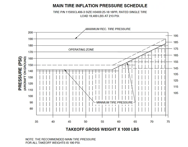
According to U.S. Federal Aviation Administration(FAA) Technical Standard Order TSO-C62c, the maximum allowable tire pressure loss is 5% per day.
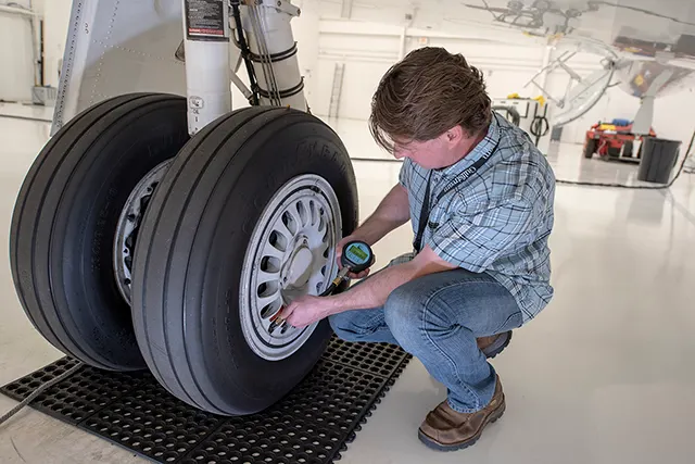 Fig- Daily measuring of tyre presuure
For example-
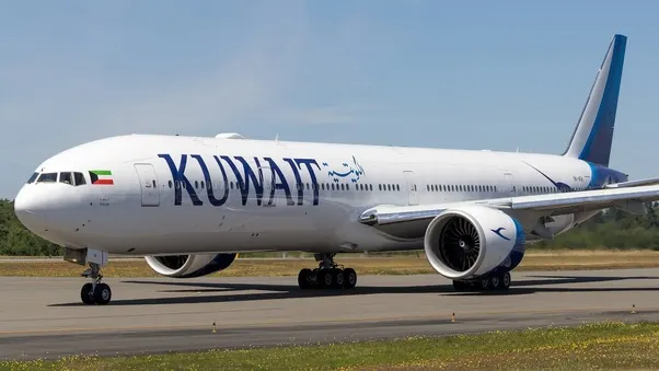 Fig- Boeing 777
A Boeing 777 fully loaded weighs around 700,000 pounds and has fourteen tires. Therefore, if each of those tires is reacting roughly the same force, then that is 50,000 pounds per tire. The tire pressure is 200 psi. Therefore there should be 250 square inches of surface contact area for each tire with the ground (250 * 200 = 50,000).
(v)Brake Forces When Landing>> Stopping an aircraft landing at 180-200 mph requires a lot of braking force. To do this, the aircraft has brake unit on each of the wheels on the main gear assembly. On landing, pilots should use aerodynamic braking by applying extra back-pressure on the stick or yoke. Extreme caution should be used when applying brakes at any significant speed, and only when the end of the runway is quickly approaching. Never step on the brakes to make a runway exit. Applying the brakes at too high a speed could burn the tires, wear out the brakes, or result in a ground loop or swerve.
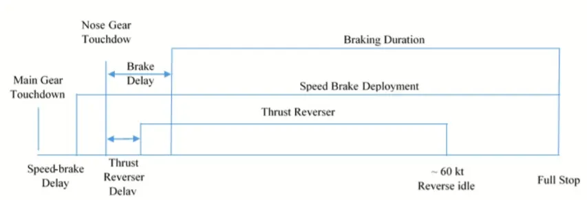
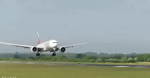
Aircraft braking systems include:
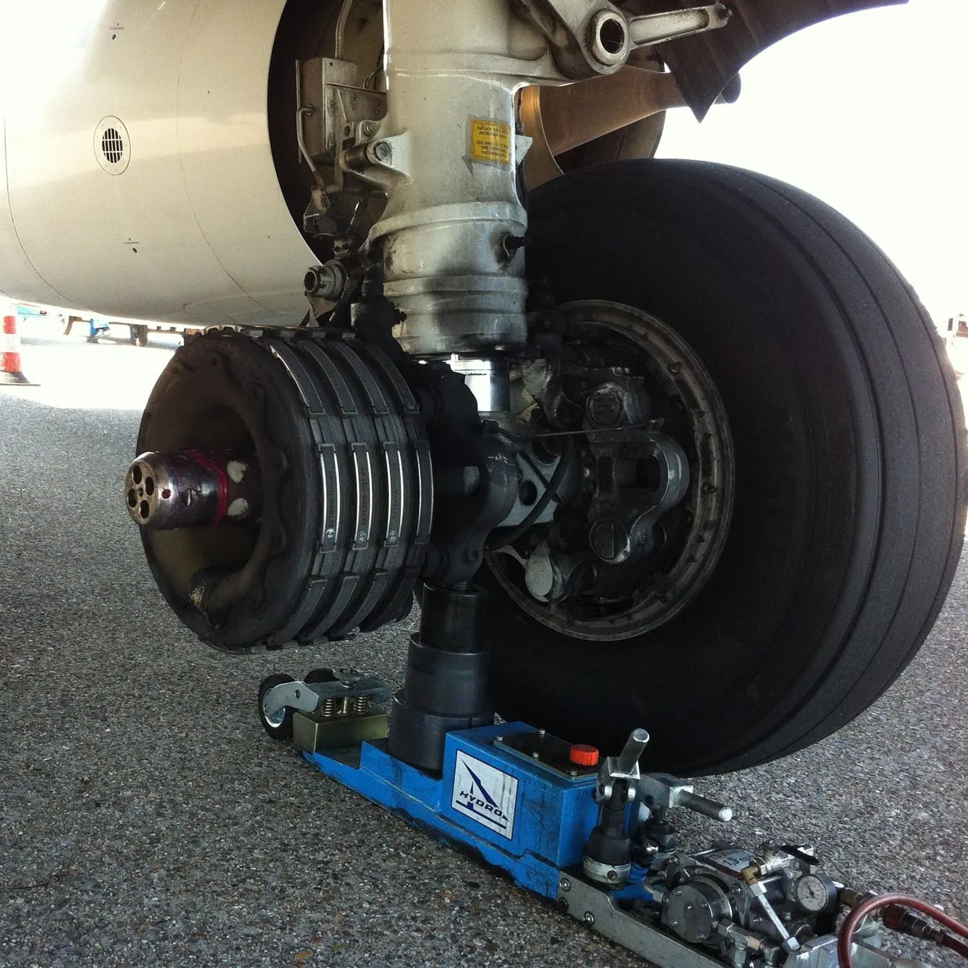
- Aircraft Disc Brake: In the landing gear it is used to brake the wheels while touching the ground. These brakes are operated hydraulically. In most modern aircraft they are activated by the top section of the rudder pedals ("toe brakes"). In some older aircraft the bottom section is used instead ("heel brakes"). Levers are used in a few aircraft. Most aircraft are capable of differential braking.
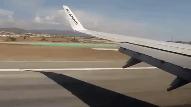
- Thrust Reverse: that allow thrust from the engines to be used to slow the aircraft.

- Air Brake: It is dedicated flight control surface, that work by increasing drag.
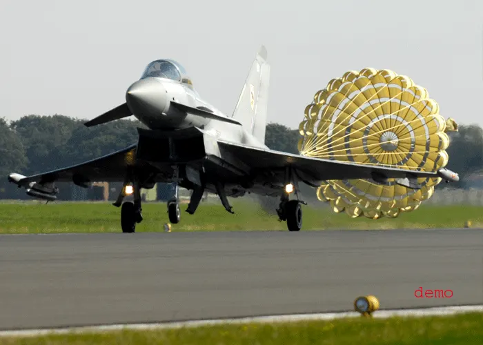
- Drogue Parachute: It is used by several former and current military and civilian aircraft (examples include the American B-52 and the soviet Tu-134 and Tu-144).
STUDY 6: Calculating The Force and Power Required to Push / Pull An Aircraft by a Towing Vehicle To push or pull an aircraft by a towing vehicle, 3 type of forces will act on that vehicle. Those are -(i) Rolling resistance force (ii) Aerodynamic drag force and (iii) Hill climbing force.
(i) Rolling resistance force(Frr) : Rolling resistance is the force resisting the motion when a body rolls on a surface. It is the friction force that is needed to be overcome to move a vehicle. The kinetic energy of the wheels is partially converted into heat. The rolling resistance is proportional to the normal force perpendicular to the rolling wheel and is approximated by the rolling resistance coefficient urr. Therefore, Equation that can be used for the rolling resistance force of the entire system is-
Frr = urr * m * g where, urr= Rolling resistance co-efficient (It depends on the tire material, tire structure, tire temperature, road roughness, road material etc.) m= Total mass of the vehicle (vehicle mass + payload) in kg g = gravitational constant , that is 9.8 m/s^2
| urr of Car for different condition- | |
| CONDITION | urr |
| Tires on concrete or asphalt | 0.013 |
| Tires on rolled gravel | 0.02 |
| Tar macadam | 0.025 |
| Unpaved road | 0.05 |
| Field | 0.1 - 0.35 |
Here in this case for towing vehicle for aircraft urr= 0.013
(ii) Aerodynamic drag force(Fad) : Aerodynamic drag force is the force which is required to keep a vehicle moving. There are two component of this force , one is shape drag (due to the shape of the vehicle) and another is skin friction (due to friction between air and skin of the vehicle). When the vehicle moves the velocity of air near boundary is higher than the air surrounding. Both the tug and the aircraft will experience some aerodynamic drag. For completeness, the aerodynamic drag force caused by the aircraft and towing vehicle can be given by Equation below-
Fad = (1/2) * ρ * V^2 * A * (Cd_t + Cd_a) where, ρ = Air density, that is normally 1.25 kg/m^3 A = Frontal area of the vehicle in m^2 Cd_t = Air drag co-efficient of towing vehicle (It depends on frontal area, shape, protrusions, ducts, air passage etc.) Cd_a = Air drag co-efficient of aircraft (It depends on frontal area, shape, protrusions, ducts, air passage etc.) v = Velocity of the vehicle in m/s
With regard to the drag equation, the term A simply refers to some reference area. For airplanes, this is generally the planform area of the wing The designers design an aircraft in such a way that the reference area is optimal. So, for calculation this has been neglected.
| Cd for different types of vehicle- | |
| VEHICLE TYPE | Cd |
| Open Convertible | 0.5 - 0.7 |
| Van body | 0.5 - 0.7 |
| Ponton body | 0.4 - 0.55 |
| wedge- shaped body, head lamps and bumpers are integrated into the body, covered undeready optimized cooling air flow |
0.3 - 0.4 |
| Motor cycle | 0.6 - 0.7 |
| racing car | 0.2 - 0.25 |
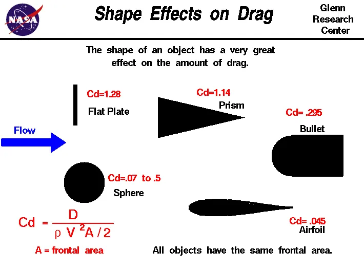 In this case air drag co-efficient for towing vehicle(Cd_t)= 0.5 and for aircraft or payload(Cd_a)= 0.045.
(iii) Hill climbing force(Fhc) : Hill climbing force is the force needed to move the vehicle in up gradient. To Hill Climbing force the expression of the equation is given below-
Fhc = m * g * sinφ where, m = Total mass of the vehicle(vehicle mass + payload) in kg g = Gravitational constant that is 9.8 m/s^2 φ = up gradient angle or inclination angle in radian
In this case up gradient angle(φ) = 0, as there is no inclination.
Push/Pull Power Calculation of Towing Vehicle- Let's assume, the towing vehicle mass = 50000 Kg the aircraft mass or payload on towing vehicle = 183700 Kg total mass of the vehicle(m) = (50000+183700) = 233700 Kg towing vehicle fontal area(A) = 20 m^2 speed of the vehicle(V) = 30 Km/hr = 8.333 m/s
Rolling Resistance Force(Frr) = urr * m * g =0.013 * (50000+183700) * 9.8 =29,773.38 N
Aerodynamic Drag Force(Fad) = (1/2) * ρ * V^2 * A * (Cd_t + Cd_a) = (1/2) * 1.225 * (2.778)^2 * 20 * (0.5+0.045) = 51.514 N
Hill Climbing Force(Fhc) = m * g * sinφ =(50000+183700) * 9.8 * sin0 = 0 N
Total required traction power(Tf) = Frr + Fad + Fhc =29773.38 + 51.514 + 0 =29824.894 N
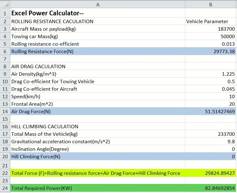
Push/Pull Power Calculation of Towing Vehicle- Excel Power Calculator
STUDY 7: Design An Electric Powertrain to Fulfill Aircraft Towing Application
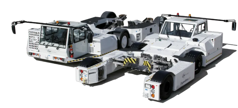
Table for the necessary assumed parameters-
| Assumtion For Powertrain Design- | |
| Aircraft Mass | 183700 Kg |
| Towing Vehicle Mass | 50000 Kg |
| Rolling Resistance Co-efficient | 0.013 |
| Air Density | 1.225 kg/m^3 |
|
Towing Vehicle Drag Co-efficient |
0.5 |
| Aircraft Drag Co-efficient | 0.045 |
| Frontal area | 20 m^2 |
| Inclination Angle | 0 rad |
| Tyre Pressure | 203 PSI/14 bar |
| Towing Velocity(V) |
10km/h =2.778m/s |
| Towing Time(t) | 2 min |
| Radius of the towing vehicle wheel |
0.38 m |
Therefore from the excel power calculator we have got the necessary Traction force(F) quantity that is = 29824.89427 N
and Required power(P) = F * V = 29824.894 * 2.778 =82846.928 W = 82.846 KW As we know Torque(T) = Force(F) * Wheel radious(r)
So, from the above equation we have got the required torque(T) = 29824.894 * 0.38 = 11333.45972 N-m.
Required Energy(E) for towing application based on the assumed time, that is E = P * t = 82.846 * (120/3600) = 2.761 KWh
For this application an Induction motor or a BLDC can be used with a proper gear system.
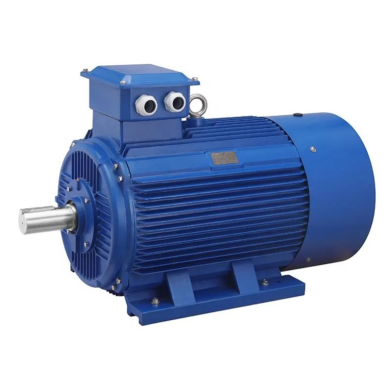 Fig- Induction Asynchronous motor
| Induction Motor Rating- | ||||||
| Output Mechanical Power |
Horse Power |
Input In term of Mechanical Power |
No of Phases |
Input Voltage | Input Current | Efficiency |
| 90 KW | 120 H.P | 95.642 KW | 3 | 380 V | 163.3 A | 94.10% |
| 400 V | 155.1 A | |||||
| 415 V | 149.5 A |
The motor output power is the input power of the towing vehicle so to obtain maximum speed, the duty cycle needed is calculated as below- Duty Cycle = Output Power/Input Power = (82.846/90)*100 = (0.921*100)%, so the duty cycle will be 92.1% The duty cycle range to control the aircraft speed from zero to highest is from 0 to 92.1 %
Towing Vehicle simulink Powertrain Block model- 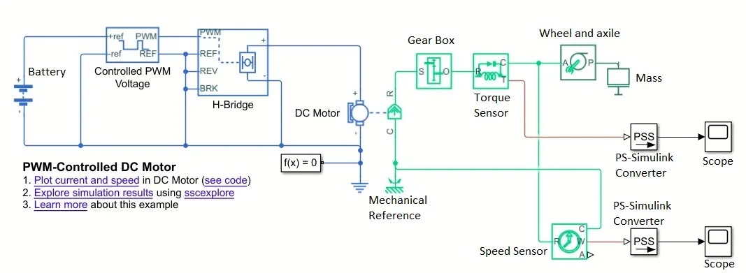 Though a Induction motor has been choosed for this application but here this simulink model is built