Project-1: Powertrain for aircraft in runways
Part A:
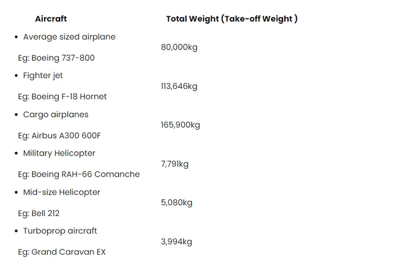
1. Search and list out the total weight of various types of aircrafts.
The different terms represent different weights or masses1. For each flight, the weights are taken into account for several reasons.
A brief description about these is below:
(MEW)
Also called Manufacturer's Weight Empty (MWE) or Licensed Empty Weight
It is the weight of the aircraft "as built" and includes the weight of the structure, power plant, furnishings, installations, systems and other equipment that are considered an integral part of an aircraft.
This excludes any baggage, passengers, or usable fuel2.
(ZFW) Zero -fuel weight
This is the total weight of the airplane and all its contents (including unusable fuel), but excluding the total weight of the usable fuel on board.
As a flight progresses and fuel is consumed, the total weight of the airplane reduces, but the ZFW remains constant.
Maximum zero fuel weight (MZFW) is the maximum weight allowed before usable fuel and other specified usable agents (engine injection fluid, and other consumable propulsion agents) are loaded.
(OEW) Operating empty weight
It is the basic weight of an aircraft including the crew, all fluids necessary for operation such as engine oil, engine coolant, water, unusable fuel and all operator items and equipment required for flight but excluding usable fuel and the payload.
Payload
It is the carrying capacity of an aircraft. It includes cargo, people, extra fuel. In the case of a commercial airliner, it may refer only to revenue-generating cargo or paying passengers.
Maximum take off weight (MTOW)
This is the maximum weight at which the pilot of the aircraft is allowed to attempt to take off.
Regulated takeoff weight(RTOW)
Depending on different factors (e.g. flap setting, altitude, air temperature, length of runway), RTOW or maximum permissible takeoff weight varies for each takeoff. It can never be higher than MTOW.
Maximum landinng weight (MLW)
This maximum weight at which an aircraft is permitted to land3.
The following image depicts takeoff weight components.
(MRW)
also called maximum taxi weight (MTW)
It is the maximum weight authorized for maneuvering (taxiing or towing) an aircraft on the ground.
Aircraft gross weight.
It is the total aircraft weight at any moment during the flight or ground operation. This decreases during flight due to fuel and oil consumption.
a) Crew weight (Wc )
The crew comprises the people necessary to operate the airplane in flight.e.g., Pilot, Co-pilot, Airhostess etc.
b) Payload weight ( Wp )
The payload is what the airplane is mentioned to transport passengers, baggage, freightetc. (Military use the payload includes bombs, rockets and other disposable ordnance) .
c) Fuel weight ( W f )
This is the weight of the fuel in the fuel tanks. Since fuel is consumed during the course offlight. is a variable, decreasing with time during the flight.
d) Empty weight ( We )
This is weight of everything else-the structure engines (with all accessory equipment),electronic equipment landing gear, fixed equipment and anything else that is not crew, payloador fuel.
e) Gross weight ( W0 )
The sum of these weights is the total weight of the airplane. Gross weight or total weightvaries through the flight because fuel is being consumed. The design take off gross weight is theweight of the airplane at the instant it begins its mission. It includes the weight of the fuel.
Different types of aircrafts with their weight -
2. Is there any difference between ground speed and air speed?
Airspeed vs. Ground Speed
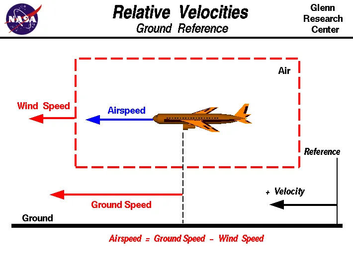

ground speed is the airplane’s speed relative to the surface of the Earth, airspeed – at least true airspeed – is its speed relative to the air it is flying in.
As mentioned above, true airspeed is simply the speed at which an aircraft is moving relative to the air it is flying in. As such, it’s also the speed at which the air is flowing around the aircraft’s wings.
Ground speed, on the other hand, is the aircraft’s speed relative to the ground. One thing that should be noted here is that it’s its horizontal rather than vertical speed – an aircraft climbing completely vertically would have a ground speed of zero.
In other words, while airspeed is what determines whether there is enough airflow around an aircraft to make it fly, ground speed is what determines how fast an aircraft will get to its destination.
3. Why is it not recommended to use aircraft engine power to move it on the ground at Airport?
Engine power is used all the time to move aircraft on the ground. I think you mean in the ramp area. if, so, again, engine power is used all the time in the ramp. They do get pushed back because only aircraft with engines on the tail can power-back due to FOD. Sometimes, if it’s a tight area, a tug will be used.

Airplanes have engines, and they can use them to move forward along the ground. So they push themselves to the runway.
It is true that most of the time, a small vehicle is needed to push the larger commercial airplanes backwards away from the terminal building, because even if a plane can reverse it’s thrust, it’s not always safe to hit the buildings with that reverse thrust. So the little trucks push the bigger planes back away from the buildings, but after that, the planes can apply a small amount of engine power to roll forward just as all airplanes can.
Aircraft push themselves to the runway.
5. Learn about take off power, tyre design, rolling resistance, tyre pressure, brake forces when landing.
Take Off Performance
Take off performance can be predicted using a simple measure of the acceleration of the aircraft along the runway based on force equilibrium.
The forces involved will be,
T – Thrust of propulsion system pushing aircraft along runway.
D – Aerodynamic Drag of vehicle resisting the aircraft motion.
F – Rolling resistance friction due to the contact of wheels or skids on the ground.
During take-off run the imbalance in these forces will produce an acceleration along the runway.
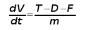
where dV/dt is the acceleration along the runway and m is the mass of the vehicle.
1. Rotation Velocity.
The procedure for take-off will be that the vehicle will accelerate until it reaches a safe initial flying speed, the pilot can then rotate the vehicle to an attitude to produce climb lift and it will ascend from the ground. The determination of this safe flying speed or rotation speed, VR, is a critical factor in determining take-off performance.
For safety reasons VR is usually determined as being 1.2 * VSTALL or 1.1*VMIN CONTROL which ever is greater. Stall speed, VSTALL, is the lowest speed that the aircraft can be flown before the airflow starts to separate from wings as the angle of attack becomes too great. It can be calculated based on knowledge of the aircraft take-off configuration and hence the maximum achievable lift coefficient CL(max). To maintain level flight the lift produced must equal the weight, at the point just before stall this leads to the following balance,
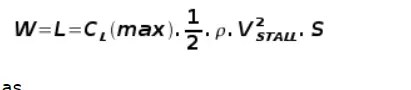
hence stall speed can be calculated as,
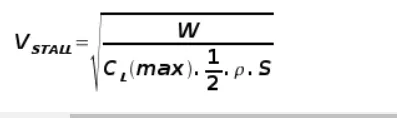
Minimum control speed, VMIN CONTROL is a more complex calculation and requires knowledge of the stall characteristics of the tailplane and elevator. For conventional aircraft there is only a small difference between VR calculations based on stall speed or minimum control speed.
As well as rotation speed there are other safety considerations as shown in the following figure.
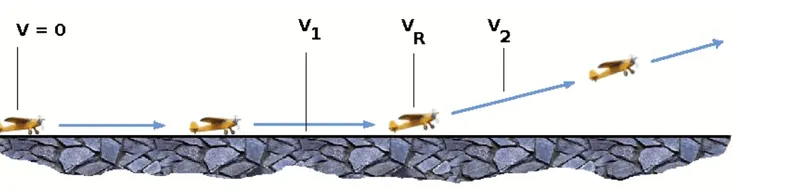
V1- Abort decision speed. Below this speed the take-off can be safely aborted. After this there will not be sufficient runway length to allow the aircraft to decelerate to a stop.
V2 – Safe climb speed. Below this speed aircraft cannot attain sufficient climb rate. Aircraft must climb at a minimum gradient to avoid obstacles at the end of the runway. With engine failure on multi-engined aircraft, this speed should still be achievable.
2. Thrust
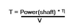
The thrust of gas turbine or turbofan engines will be relatively constant during take-off. A good assumption is to use the manufacturer's values for maximum static thrust for take-off calculations.
The thrust of a propeller driven aircraft can be found from the given shaft horsepower data for the engine and the use of the equations using propeller efficiency given in the previous section.
It is critical to correctly estimate the propeller efficiency for the particular aircraft velocity along the runway. At V=0 the efficiency is 0 and at V=VR the efficiency will be in the range 50% to 80% depending on the type of propeller system used.
3. Drag
The resistance to motion due to the air viscosity will give a drag of
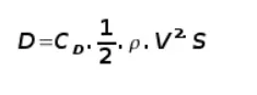
where CD can be considered constant and calculated using the formula shownin the previous section
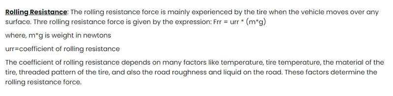
4. Rolling Resistance
The friction between aircraft and runway will be proportional to the normal force exerted by the aircraft on the runway.
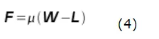
The normal force will be the difference between Weight of aircraft and Lift, the friction coefficient will be typically of a magnitude of 0.02 for a standard tarmac runway.
5. Average acceleration and distance to rotation.
The rate of change of velocity can be predicted at any point on the take-off roll by substituting results (2),(3) and (4) into equation (1). The subsequent velocity can be found by integrating this result and the distance traveled found by integrating the velocity.
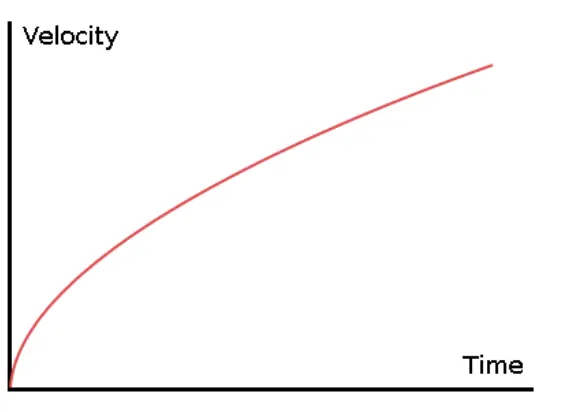
A typical acceleration will be dominated by the drag component as thrust, weight and friction are relatively constant during this period. This leads to the result shown where acceleration is inversely proportional to velocity2.
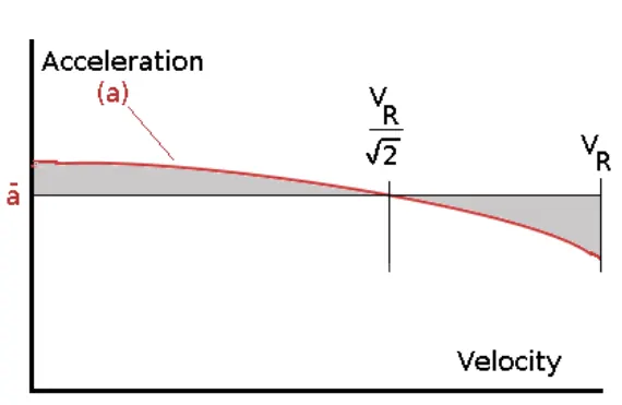
Due to the quadratic nature of acceleration change, an average value, for the range of velocities from zero to VR can be found at the point when 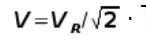 . This average acceleration can be used to simplify calculations and the take-off run can be assumed to be a constant acceleration for the time taken to get from 0 to VR.
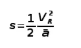
This means and where t is time from start to point where VR is attained. Rearranging leads to a relatively simple calculation to predict take-off distance.
6. Take-Off (Balanced) Field Length.
The required length of runway will be the sum of the distance required to get to rotation speed and the extra length required to allow for rapid braking if the pilot decides to abort take-off at the decision speed V1. This length will typically be considerably longer than the distance required to achieve flying speed.
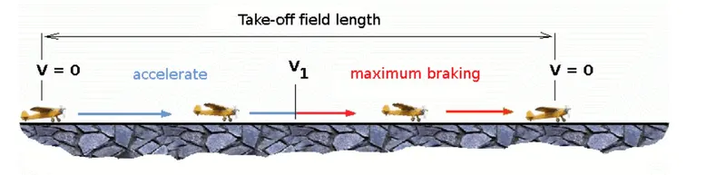
Distance to V1 can be calculated in a manner similar to that shown for VR. The calculation of braking distance will require knowledge of the maximum braking friction coefficient that can be generated by the aircraft. This information should be available from manufacturer's data. Braking distance calculations should also be done without any assumption of reverse thrust from engines as during a take-off abort, engine power may not be available.
tire of aircraft-
Many aviation technicians are not aware of the critical design factors of aircraft tyre in use today. I will discuss step by step, but first, I would like to ask the importance of tyre in aircraft.
Why are tyres important in Aircraft?
When it comes to safety, tyres are one of the most important components of aircraft. They help to absorb the shock of landing and provide cushioning. It also provides the necessary traction for braking and stopping of an aircraft.
An aircraft tyre is designed to withstand extremely heavy loads while landing, take off, taxing, and parking. The number of wheels required for aircraft increases with the weight of the aircraft, as the weight of the aeroplane needs to be distributed more evenly.
A Boeing 737NG & 737MAX uses 6 wheels, Boeing 787 uses 10 wheels, Boeing 777 uses 14 wheels and Airbus A380 uses 22 wheels. Aircraft tyres work under extreme conditions, carrying up to 340 tons and accelerating at over 250 km/hour at takeoff, in addition to enduring varied environmental stress when in flight and taxiing.
Design and Construction of Aircraft tyre
Carcass plies are used to form the tire. They are sometimes called casing plies. An aircraft tyre is constructed for the purpose it serves.
- They support the weight of an aircraft while it is on the ground.
- It also provides the necessary traction for braking and stopping of an aeroplane.
- Tyre also helps to absorb the shock of landing and provide cushioning the roughness of takeoff, roll-out, and taxi operations.
Unlike an automobile or truck tyre, it does not have to carry a load for a long period of continuous operation. However, an aircraft tyre absorbs the high impact loads of landing, and also it’s operating at high speeds for a short time when required.
Let’s go through some technical aspects of the tyre.
Retreading – Retreading is methods of restoring a worn tyre by renewing the tread area or by renewing the tread area plus one or both sidewalls. Repairs are included in the tyre retreading process.
Load Rating – Load rating is the maximum permissible load at a specified inflation pressure.
Ply Rating – Ply Rating is used to identify the maximum recommended load rating and inflation pressure for a specified tyre. It is an index of tyre strength.
Speed Rating – The speed rating is the maximum takeoff speed to which the tyre has been tested.
Skid Depth – Skid depth is the distance between the tread surface and the deepest groove as measured in the mould.
Aircraft tyres must have an approved speed and load rating and have sufficient clearance when retracted through landing gear to allow for tyre growth. Tyre growth is the increase in the size of the tyre due to centrifugal forces at high speed.
Aircraft tyres may be Tube-type or Tubeless
Tubeless tyres are more advantageous over tube-type. There is no longer the use of tube-type tyre in recent aviation. Nowadays all airliners are using tubeless tyres. Tubeless that are meant to be used without a tube has the word TUBELESS on the sidewall of the tyre.
Aircraft tyres may be Radial or Bias
Almost all airliners are using Radial tyre. Bias is an older design, and it’s mainly used for road vehicles. Radial tyres have the word RADIAL on the sidewall. Radial tires are more expensive than bias-ply tyres. Radial tires are in demand because of their lower life cycle cost and long term value.
The basic difference between a radial tyre and bias (cross-ply) tyre is the lay of the plies within the tyre carcass. The remainder of the tyre is very similar in construction in both.
Tyres are critical components of aircraft. The choice of tyre totally depends on the aircraft manufacturer. Radial tyres having a feature of rigid belt and flexible carcass which providing more number of landings and less rolling resistance.
Another means of classifying an aircraft tyre is by the direction of the plies used in the construction of tyre , either bias or radial. Traditional aircraft tyres are bias-ply tyres.
So, let’s take a look at major differences between radial and bias-ply tyre.
Construction of Aircraft Radial & Bias Tyre
A radial tyre has the fibre strands of the ply fabric oriented with and at 90° to the direction of rotation and the tyre sidewall. This restricts flexibility bidirectionally and the flexibility of the sidewall while it strengthens the tyre to carry heavy loads.
A bias-ply tyre has the fabric bias oriented with and across the direction of rotation and the sidewall. Since fabric can stretch on the bias, the tyre is flexible and can absorb loads. Tyre strength is obtained by adding plies.
Puncture and Cut Resistance of Tyre
Most radial tyres are resistant to penetrations and cuts, especially in the tread area due to their unique construction process. In fact, only a small portion of the radial tyre will be affected in case of any damage.
Bias-ply tires are cut resistant in the sidewall area. However, if there is any cut in the tread area, it can affect only a small portion of tyre.
Traction Properties for Aircraft Tyre
Due to stiffer tread in radial tyres, they distribute weight evenly. These results provide consistent contact patch and greater traction, which means the tyres wear less and longer tread life.
While bias-ply tyres do not offer as much smoothness in terms of riding quality, their strong and stable sidewalls more than make up for it, especially this use in heavy-duty carriage trucks and buses.
Heat Tolerance of Aircraft Tyre
Aircraft tyre generates more heat during landing. Aircraft drags the wheel until they match the rotational velocity of wheels. Due to this heat generates.
However, each tyre is built to operate within a given temperature. This is known as vulcanization temperature. During the course of its use, if the tire is heated past the vulcanization temperature, it begins to wear gradually.
Radial tires have an advantage over the bias-ply tire in terms of reducing heat better.
Which is better radial or bias tyre?
Radial tyres are a newer design. Traditional aircraft were using Cross Ply tyre. The choice of tyre in aircraft only depends on manufacturer type certificate data sheet. Radial tyres are in demand because of their long term value, although they are more expensive than bias-ply tyres.

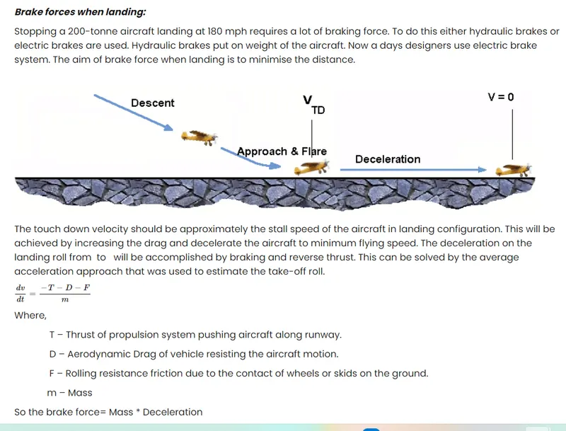
Brake force whille landing-
Part B:
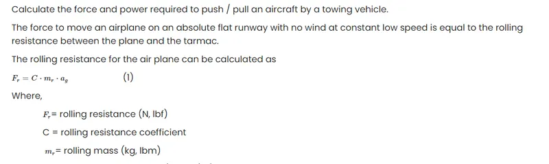
6. A. With necessary assumptions, calculate the force and power required to push / pull an aircraft by a towing vehicle.
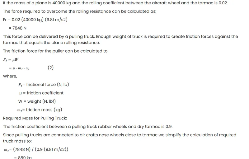
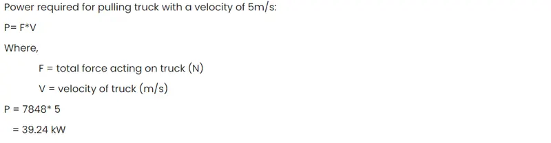
B. Develop the model for the calculated force and power using Simulink.
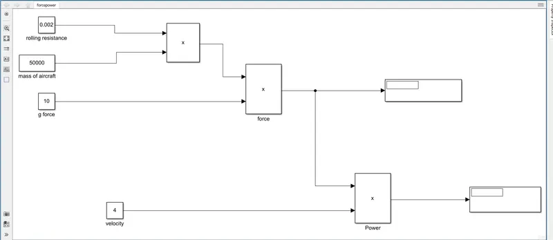
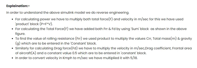
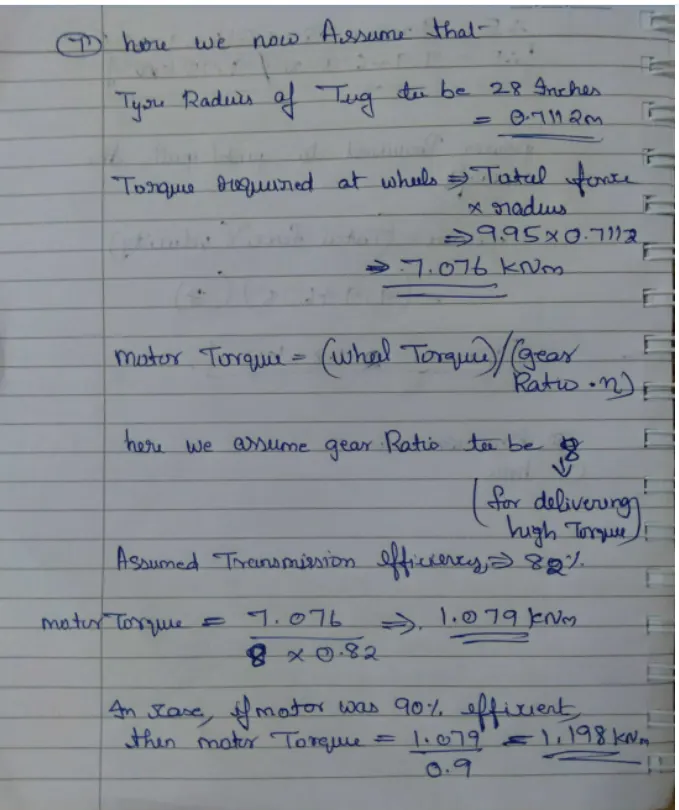
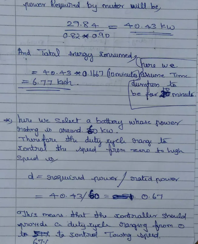
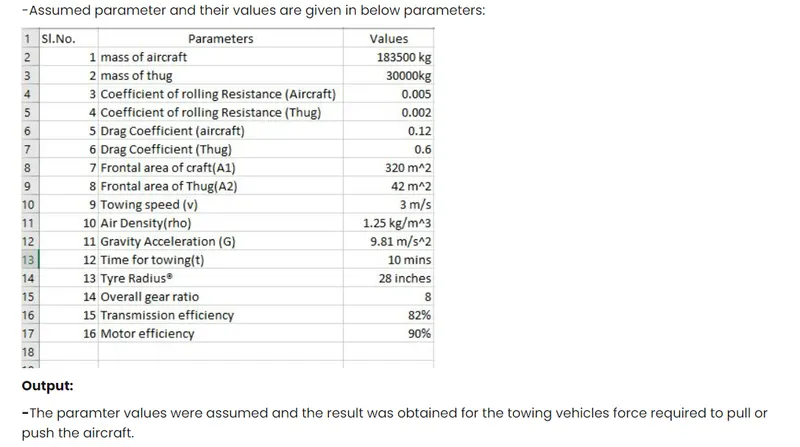
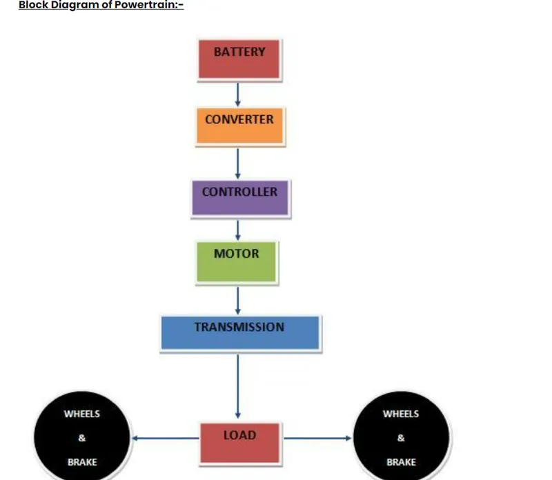
7. A. Design an electric powertrain with type of motor, it’s power rating, and energy requirement to fulfill aircraft towing application in Simulink. Estimate the duty cycle range to control the aircraft speed from zero to highest. Make all required assumptions. Prepare a table of assumed parameters. Draw a block diagram of powertrain.
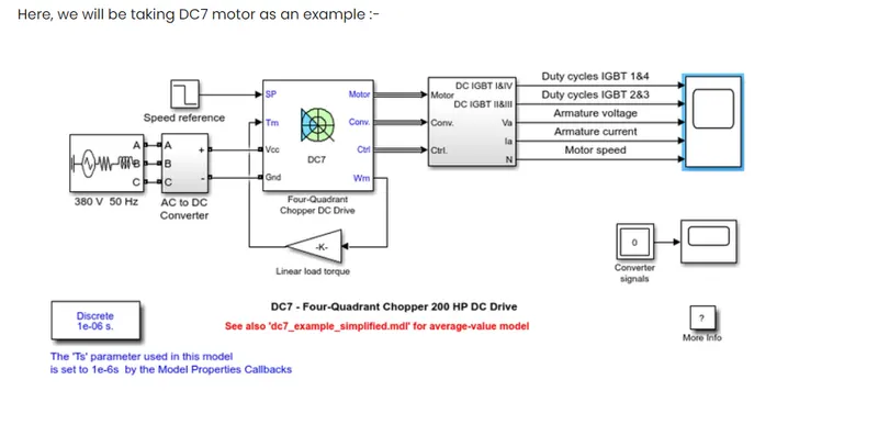
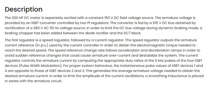
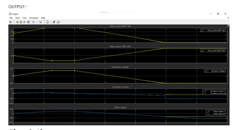
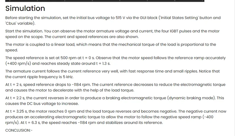
(Hint :DC7 Block)
B. Also, Design the parameters in excel sheet.
 \
\