Project-1: Powertrain for aircraft in runways
Objectives:
Part A:
1. Search and list out the total weight of various types of aircrafts.
2. Is there any difference between ground speed and air speed?
3. Why is it not recommended to use aircraft engine power to move it on the ground at Airport?
4. How an aircraft is pushed to runway when its ready to take off?
5. Learn about take off power, tyre design, rolling resistance, tyre pressure, brake forces when landing.
Part B:
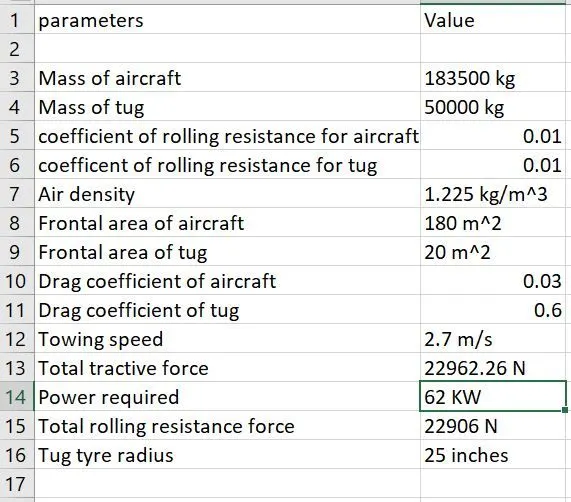
6. A. With necessary assumptions, calculate the force and power required to push / pull an aircraft by a towing vehicle.
B. Develop the model for the calculated force and power using Simulink.
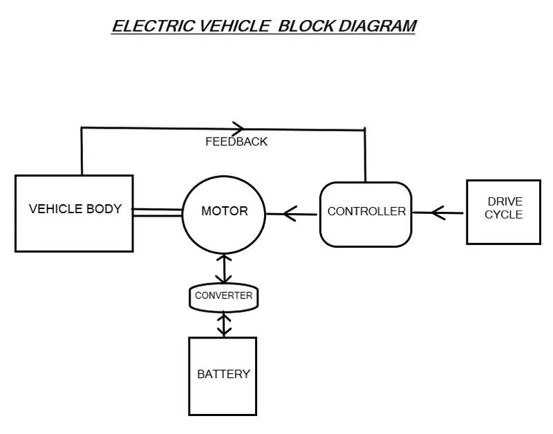
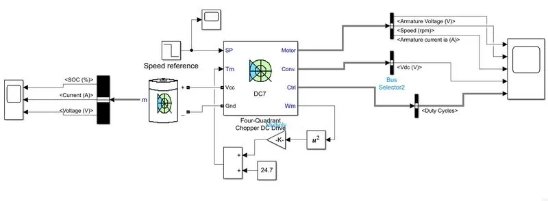
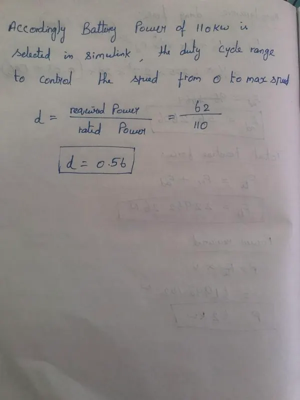
7. A. Design an electric powertrain with type of motor, it’s power rating, and energy requirement to fulfill aircraft towing application in Simulink. Estimate the duty cycle range to control the aircraft speed from zero to highest. Make all required assumptions. Prepare a table of assumed parameters. Draw a block diagram of powertrain.
(Hint :DC7 Block)
B. Also, Design the parameters in excel sheet.
Part A:
1. Search and list out the total weight of various types of aircrafts.
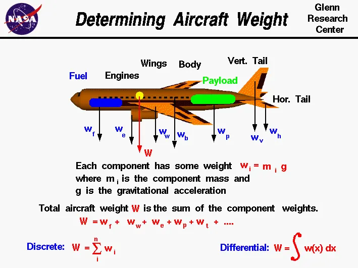
is the force generated by the gravitational attraction of the earth on the airplane. Each part of the aircraft has a unique weight and mass, and for some problems it is important to know the distribution. But for total aircraft maneuvering, we only need to be concerned with the total weight and the location of the center of gravity. The center of gravity is the average location of the mass of any object.
How do engineers determine the weight of an airplane which they are designing?
An airplane is a combination of many parts; the wings, engines, fuselage, and tail, plus the payload and the fuel. Each part has a weight associated with it which the engineer can estimate, or calculate, using Newton's weight equation:
w = m * g
where w is the weight, m is the mass, and g is the gravitational constant which is 32.2 ft/square sec in English units and 9.8 meters/square sec in metric units. The mass of an individual component can be calculated if we know the size of the component and its chemical composition. Every material (iron, plastic, aluminum, gasoline, etc.) has a unique density. Density r is defined to be the mass divided by the volume v:
r = m / v
If we can calculate the volume
m = r * v
The total weight W of the aircraft is simply the sum of the weight of all of the individual components.
W = w(fuselage) + w(wing) + w(engines) + w(payload) + w(fuel) + ...
total weight of various types of aircrafts.
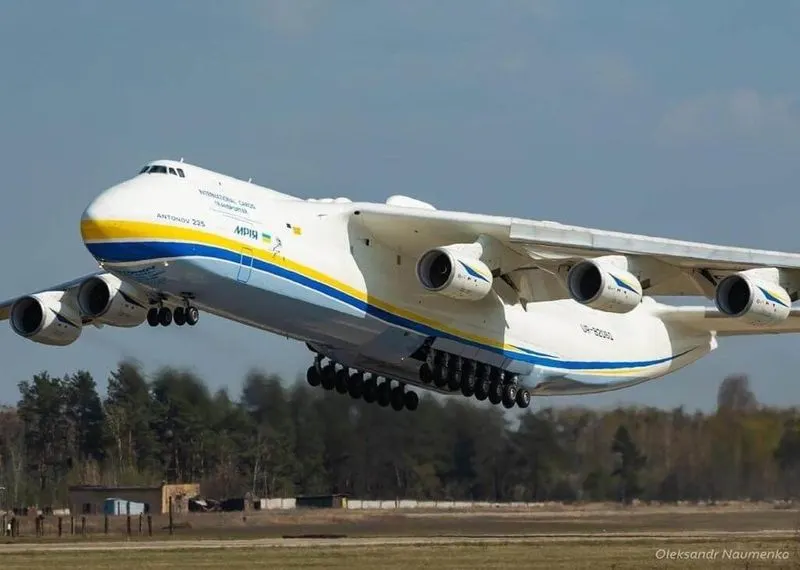
Antanov AN-225 - Soviet Union
| Aircraft | Empty Weight | Max Fuel Weight | Max Cargo Weight | Max Gross Takeoff Weight |
|---|---|---|---|---|
| Antanov AN-225 | 285,000 kg | 300,000 kg | 190,000 kg | 640,000 kg |
| Aircraft | Empty Weight | Max Fuel Weight | Max Cargo Weight | Max Gross Takeoff Weight |
|---|---|---|---|---|
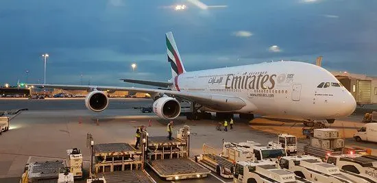
| Airbus A380-800 | 277,000 kg | 254,000 kg | 84,000 kg | 575,000 kg |
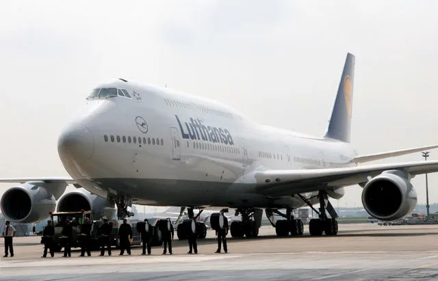
| Aircraft | Empty Weight | Max Fuel Weight | Max Cargo Weight | Max Gross Takeoff Weight |
|---|
| Boeing 747-800 | 220,100 kg | 194,000 kg | 134,000 kg | 447,700 kg |
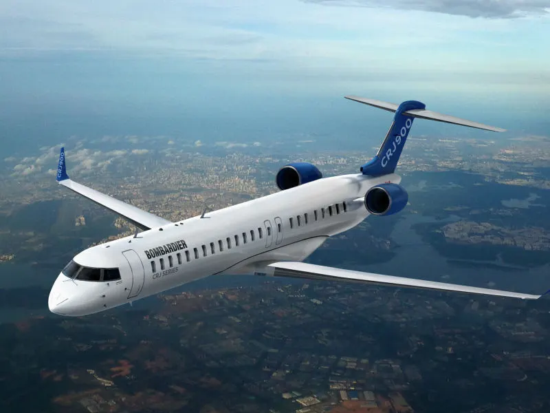
| Aircraft | Empty Weight | Max Fuel Weight | Max Cargo Weight |
Max Gross Takeoff Weight |
|---|
| Bombardier CRJ900 | 21,850 kg | 8,900 kg | 2,760 kg | 36,500 kg |
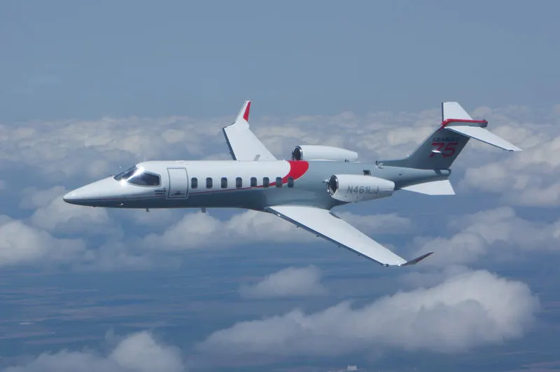
| Aircraft | Empty Weight | Max Fuel Weight | Max Cargo Weight | Max Gross Takeoff Weight |
|---|
| Learjet 75 | 6,300 kg | 2,750 kg | 1,300 kg | 9,700 kg |
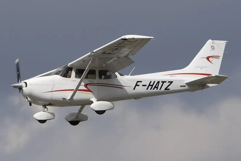
| Aircraft | Empty Weight | Max Fuel Weight | Max Cargo Weight | Max Gross Takeoff Weight |
|---|
| Cessna 172R | 770 kg | 170 kg | 255 kg | 1,100 kg |
| Aircraft | Empty Weight | Max Fuel Weight | Max Cargo Weight | Max Gross Takeoff Weight |
|---|
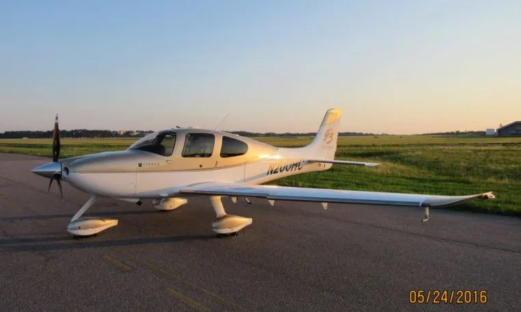
| Sirrus SR22 | 1,000 kg | 220 kg | 430 kg | 1,630 kg |
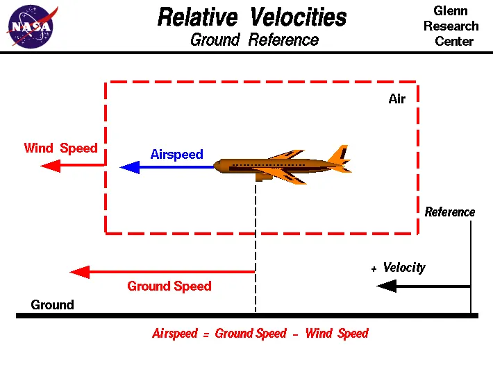
Airspeed vs. Ground Speed
Airspeed is simply the speed at which an aircraft is moving relative to the air it is flying in. As such, it’s also the speed at which the air is flowing around the aircraft’s wings.
Ground speed, on the other hand, is the aircraft’s speed relative to the ground. One thing that should be noted here is that it’s its horizontal rather than vertical speed – an aircraft climbing completely vertically would have a ground speed of zero.
In other words, while airspeed is what determines whether there is enough airflow around an aircraft to make it fly, ground speed is what determines how fast an aircraft will get to its destination.
3. Why is it not recommended to use aircraft engine power to move it on the ground at Airport?
It is a highly fuel-consuming and noisy process. It is also potentially hazardous for personnel working near the plane.
Once the plane is tugged away to a safe distance from the terminal, the plane begins using its own engine power for the rest of the taxing process.
4. How an aircraft is pushed to runway when its ready to take off?
Airplanes use their jet engines for taxing just like for flying. And they have no additional engines to power the wheels.
The wheels of an airplane rotate freely as the plane depends on the thrust from its jet engines to propel it forwards or backwards.
However despite the engines being capable of powering the airplane's 'pushback' from the terminal/gate, they are rarely used for this purpose.
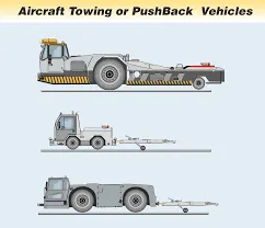
'Tug vehicles' are generally used to pushback the plane away from the terminal prior to take-off. These are specialized vehicles with high torque and heavy mass.
5. Learn about take off power, tyre design, rolling resistance, tyre pressure, brake forces when landing.
take off power
The amount of power that an engine is allowed to produce for a limited period of time for takeoff. The use of takeoff power is usually limited to 5 min for reciprocating engines and up to 2½ min for gas turbine engines. This may not always be the case. Specifically, with respect to reciprocating engines
it is the brake horsepower developed under standard, sea-level conditions and under the maximum conditions of the crankshaft rotational speed and the engine manifold pressure approved for the normal take-off. It is limited in continuous use to the period of time shown in the approved engine specifications. With respect to gas turbine engines, it is the thrust developed under static conditions at a specified altitude and atmospheric conditions of the rotor shaft rotational speed and gas temperature approved for the normal takeoff. It is limited in continuous use to the period of time shown in the approved engine specifications.
Tyre design
The tire (tyre in British English) is the only part of the aircraft in contact with the ground, and a well-maintained set of tires is crucial to the safe operation of any aircraft. Tires cushion the impact on touch-down and transfer the energy of landing into the wheels.
Aircraft tires differ substantially in their operating profile to automotive tires. Car tires are load bearing for a considerably longer time than an aircraft during a typical mission profile, albeit at relatively low speeds with slow accelerations. Aircraft tires on the other hand spend comparatively less time operating but must absorb very large impact loads and handle high speeds with large accelerations when in contact with the runway. Aircraft tires are designed to flex far more than automotive tires which assists in damping the large impact loads.
DIMENSIONS AND SIZING
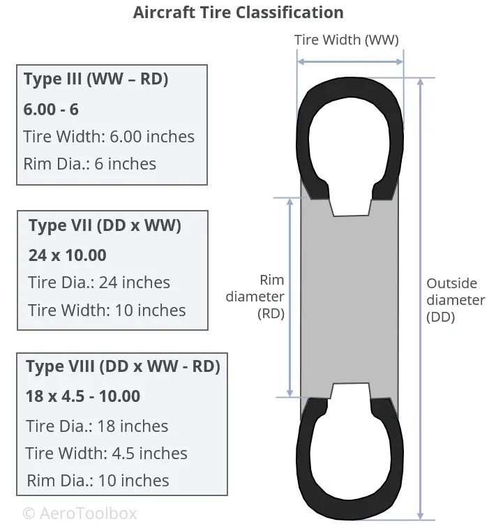
Dimensional classification is usually made according to outer tire diameter, sectional width, and the diameter of the rim. A common classification system in use today is that of the United States Tire and Rim Association, where aircraft tires are classified as one of nine types.
Today, three tire classifications cover almost all aircraft classes in use, from light aircraft up to modern jet airliners. These three classifications use a slightly different way to report the tire dimensions; this is described below.
Type III
Type III tires are common low-pressure general aviation tires predominantly used on light aircraft with reasonably low landing speeds. These tires are easily identified as they have a small rim diameter in comparison to their width. Type III tires are designated by a two-number system: the first number describes the nominal tire width and the second the diameter of the rim that the tire can be fitted to. The two numbers are separated by a dash.
Type VII
Type VII tires are high-pressure, high performance tires fitted to jet aircraft. These tires are sized according to a two-number system that differs from the Type III classification described above. Here the first number designates the nominal overall diameter of the tire while the second number, which is separated from the first by a multiplication sign, gives the nominal section width.
Type VIII
Type VIII tires are designated by three numbers and incorporate the conventions of both the Part III and Part VII tires. The first number specifies the outside diameter, the second is the nominal tire width, and the third is the rim diameter. These tires are designed to operate at high-pressures and high speeds and are the most advanced tires in use on large jet aircraft today.
PLY RATING
Ply-rating provides an indication of the relative strength of the tire. The strength of early tires was directly proportional to the number of reinforcing plies present in the design which is how the ply rating system originated. Nowadays, the use of modern materials and complex manufacturing techniques have rendered the actual ply count somewhat irrelevant when discussing to the strength of a tire. However, a ply-rating system (now decoupled from actual ply count) is still used to describe the relative strength of one tire against another and remains an important indicator of tire strength.
Construction
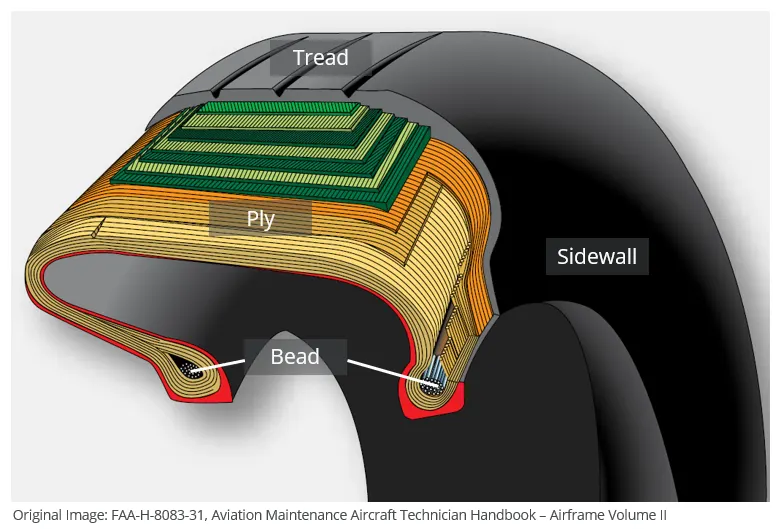
A tire follows a layered construction approach where each layer (region) of the tire serves a different purpose. Broadly speaking, a tire can be divided into four specific regions: the bead, ply, tread and sidewall.
Refer to the image below which shows the make-up of a typical aviation tire.
BEAD
The bead consists of bundles of high strength steel wire encased in rubber. This provides the tire with lateral strength, anchoring the structural plies and transferring the impact loads generated in the tire onto the wheel rim. Tires that are designed to operate at higher speeds and at higher loads may have multiple bundles of beading to effectively transfer the loads and resist the large tire deformations that result.
PLY REGION
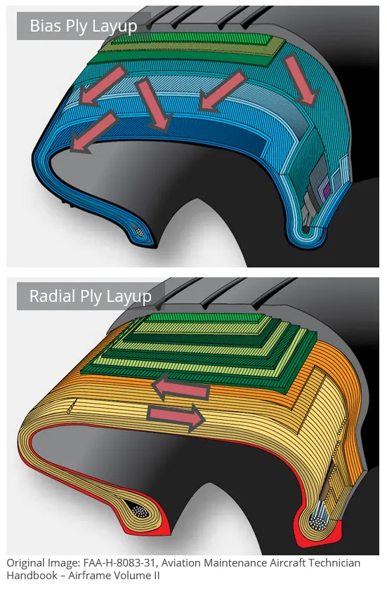
A tire is built from multiple plies which are laid on top of each-other to give the tire its structure and form. Plies are usually manufactured from nylon fabric sandwiched between layers of rubber. These structural members are sometimes called carcass plies as they form the skeleton of the tire. The concept of ply rating refers to the relative strength of the tire’s ply layup. The ends of each ply are anchored to the beading on each side of the tire to transfer load out the tire and into the wheel.
Plies are characterised according to their orientation relative to the direction of motion of the tire. Traditionally, plies were orientated predominantly in the direction of motion of the tire (with a bias of between 30° and 60°). This is called a bias ply layup as the plies are orientated with a bias to the direction of rotation. Bias plies result in a tire that is flexible and able to absorb the loads typically seen during landing and take-off.
A radial ply layup is one where the plies are laid perpendicular to the direction of motion of the tire. This results in a stronger tire, but one that is not able to deflect and flex as much as in a bias ply layup.
TREAD
The tread refers to the wearable part of the tire that is designed to come into contract with the ground. The tread is located on the tire crown and must resist frictional wear, abrasion, cracking and cuts that occur as a result of the landing surface and condition of the runway.
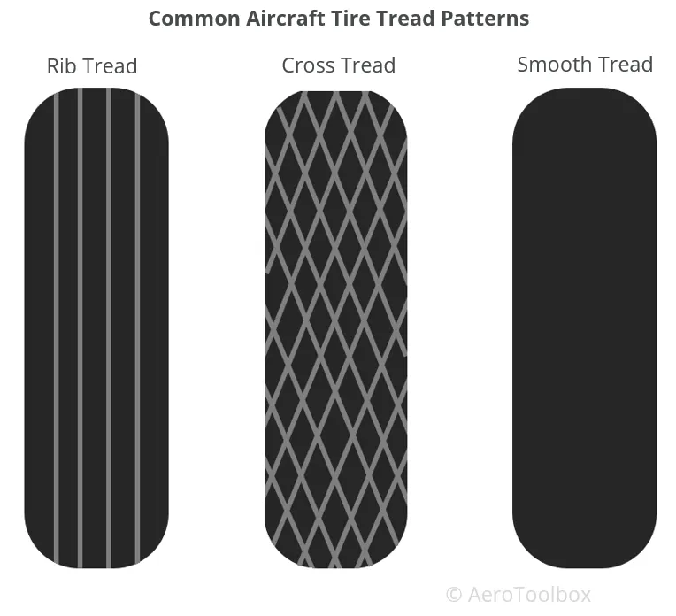
The tread pattern seen on the tire differs according to the operational requirements of the tire. Most tires are grooved in the circumferential direction which provides good operating characteristics for aircraft generally flown into and out of prepared runways. The grooves that characterize a rib tread tire assist in cooling the tire and provide a means for water to channel away from the tire in wet conditions.
Aircraft operating from unprepared or unpaved surfaces may be fitted with a cross-tread pattern. This diamond pattern is cut deep into the tire and provides more traction that the rib tread design in soft ground. On a hard surface (asphalt runway) the tire has a smaller total contact area and so will provide less traction that a tire with a rib tread.
Some older aircraft may have a smooth tread with no ribs or cut-outs. This provides the greatest traction, largest contact area, and subsequently the greatest frictional force which assists in stopping the aircraft.
SIDEWALL
The sidewall of a tire is designed to protect the plies (carcass) that gives the tire its strength. Information about the tire: its dimensions, speed rating, ply rating, direction of rotation, manufacturer etc is printed on to the sidewall for easy reference. The inner sidewall is covered by an inner liner which is a thin rubber liner designed to prevent damage to the carcass plies. Small vent holes in the sidewall are built-in to allow trapped air in the plies to escape. This helps prevent delaminations between plies from forming as a result of the trapped air expanding due to altitude and temperature changes.
Tire Wear and Creep
TIRE WEAR
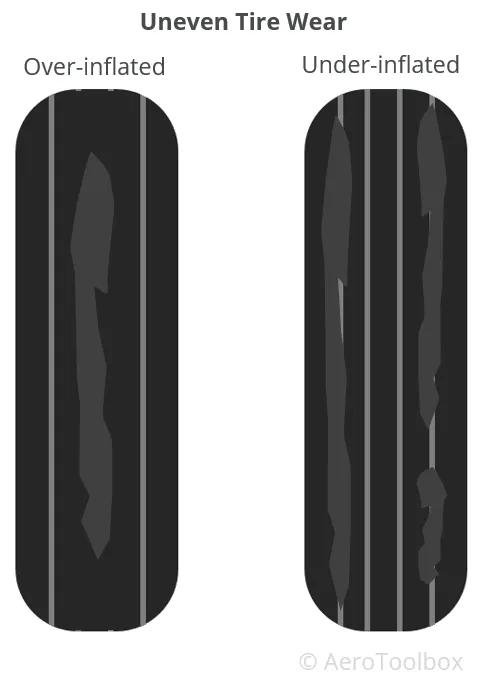
Tires that are operated at the incorrect inflation pressure result in an uneven tread wear that could be detrimental to the safety of the tire. The nature and severity of the wear can alert the pilot as to whether the tire is over or under-inflated. Considerable traction is lost when a tire has worn beyond its limits and should always be replaced or retreaded rather than left to operate in a poor condition.
A tire that is over-inflated will tend to wear towards the center of the tread. This is because at higher inflations, a smaller area of the tire is in contact with the ground and so wear is highest in this region.
Conversely, under-inflated tires will wear towards the tire shoulders as the tire sags onto the ground with a corresponding increase in friction. This can lead to the tire overheating, damage to the carcass, and the tire creeping or pinching at the sidewall.
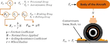
Rolling resistance
The primary function of a tire is to provide an interface between the vehicle and the road. Several forces
resist movement of the vehicle; rolling resistance forces from the tire itself, aerodynamic forces, internal
vehicle frictional forces, gravitational forces when driving up a slope and inertial forces when
accelerating/braking.
The tire rolling resistance depends of three main causes; bending before and after contact zone,
compressing and shearing in contact zone (80-95 %), micro slippage of tire to road (less than 5 %) and
aerodynamical drag due to the rotating tire function as fan resisting motion (0-15%), see figure below. The
aerodynamical drag varies with size of tire width and radius and is an almost square of velocity function.
Tyre pressure
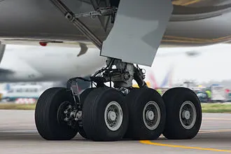
Aircraft tires generally operate at high pressures, up to 200 psi (14 bar; 1,400 kPa) for airliners, and even higher for business jets. The main landing gear on the Concorde was typically inflated to 232 psi (16.0 bar), whilst its tail bumper gear tires were as high as 294 psi (20.3 bar)
Brake forces when landing
Aircraft brakes work in conjunction with other brake mechanisms such as thrust reversers, air brakes and spoilers. Thrust reversers are surfaces that are deployed into the path of the jet blast from the engines to redirect propulsive thrust in a direction that opposes the motion of the aircraft. Air brakes and spoilers are flight control surfaces that create additional aerodynamic drag when deployed into the path of air flowing around the aircraft.
The most common type of brake used on aircraft is the disc brake. Disc brakes function by exploiting friction between rotating and stationary discs inside the brake.
Upon receiving a command signal to brake — from the pilot depressing a foot pedal or from the autobrake system — actuators in the brake move a piston to squeeze the discs together, generating a frictional force that slows the rotation of the wheel. The friction between the discs generates heat as the aircraft’s kinetic energy is converted to heat energy. In this function, the brakes act as a heat sink, absorbing tremendous amounts of heat as the aircraft sheds kinetic energy. During RTO stops, the temperature of carbon disc brakes can exceed 1,800° C.
Part B
6. A. With necessary assumptions, calculate the force and power required to push / pull an aircraft by a towing vehicle
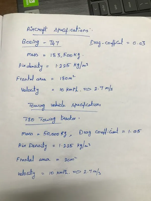
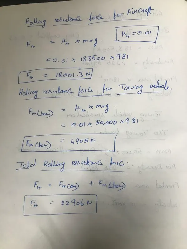
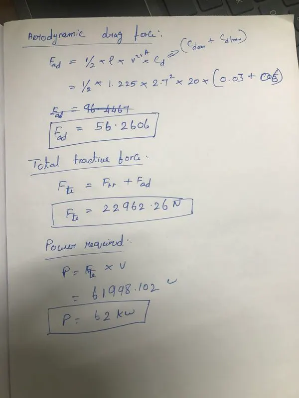
Force and power required to push / pull an aircraft by a towing vehicle is
B. Develop the model for the calculated force and power using Simulink.
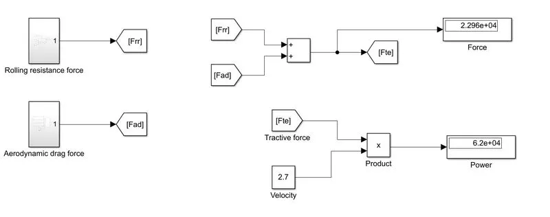
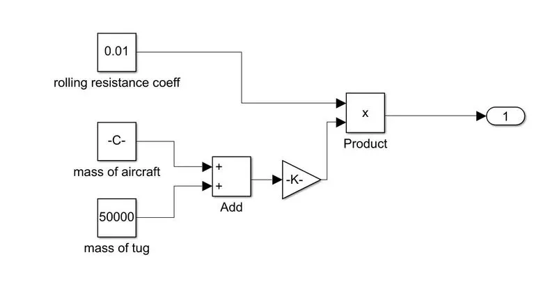
Rolling Resistance Force
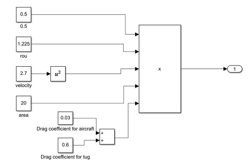
Aerodynamic Drag Force
7. A. Design an electric powertrain with type of motor, it’s power rating, and energy requirement to fulfill aircraft towing application in Simulink. Estimate the duty cycle range to control the aircraft speed from zero to highest. Make all required assumptions. Prepare a table of assumed parameters. Draw a block diagram of powertrain.
B. Also, Design the parameters in excel sheet.