Powertrain for Aircraft in Runways
Aim:
Determining the force and power required to push/pull an aircraft by a towing vehicle, and designing a suitable electric powertrain.
Objective:
- Listing out the total weight of various types of aircraft.
- Stating the difference between ground speed and airspeed.
- Stating the reason as to why aircraft is not recommended to use its engine power to move it on the ground at the Airport.
- Mentioning the way an aircraft is pushed to the runway when it's ready to take off.
- Learning on take-off power, tire design, rolling resistance, tire pressure, brake forces when landing.
- Calculating the force and power required to push/pull an aircraft by a towing vehicle.
- Designing an electric powertrain with the type of motor, it’s power rating, and energy requirement to fulfill aircraft towing application. Estimating the duty cycle range to control the aircraft speed from zero to highest as well as drawing a block diagram of the powertrain.
Procedure:
1. Total Weight of various types of Aircraft
The aircraft gross weight is the total aircraft weight at any moment during the flight or ground operation. An aircraft's gross weight will decrease during a flight due to fuel and oil consumption. An aircraft's gross weight may also vary during a flight due to payload dropping or in-flight refueling. At the moment of releasing its brakes, the gross weight of an aircraft is equal to its takeoff weight. During the flight, an aircraft's gross weight is referred to as the in-flight weight.
For each flight, the weights are taken into account for several reasons. A brief description of these is below:
Manufacturer's Empty Weight (MEW)
Also called Manufacturer's Empty Weight or Licensed Empty Weight. It is the weight of the aircraft as-built and includes the weight of the structure, power plant, furnishings, installations, systems, and other equipment that are considered an integral part of an aircraft. This excludes any baggage, passengers, or usable fuel.
Zero Fuel Weight (ZFW)
This is the total weight of the airplane and all its contents including unusable fuel, but excluding the total weight of the usable fuel on board. As a flight progresses and fuel is consumed, the total weight of the airplane reduces, but the ZFW remains constant.
Maximum zero fuel weight (MZFW)
It is the maximum weight allowed before usable fuel and other specified usable agents like engine injection fluid, and other consumable propulsion agents are loaded.
Operating Empty Weight (OEW)
It is roughly equivalent to basic empty weight on light aircraft. It is the basic weight of an aircraft including the crew, all fluids necessary for operation such as engine oil, engine coolant, water, unusable fuel, and all operator items and equipment required for flight but excluding usable fuel and the payload.
Payload
It is the carrying capacity of an aircraft. It includes cargo, people, extra fuel. In the case of a commercial airliner, it may refer only to revenue-generating cargo or paying passengers.
Maximum Take-Off Weight (MTOW)
This is the maximum weight at which the pilot of the aircraft is allowed to attempt to take off.
Regulated Take-Off Weight (RTOW)
Depending on different factors. E.g. flap setting, altitude, air temperature, length of the runway, RTOW, or maximum permissible takeoff weight varies for each takeoff. It can never be higher than MTOW.
Maximum Landing Weight (MLW)
This maximum weight at which an aircraft is permitted to land. The following image depicts takeoff weight components.
Maximum Ramp Weight (MRW)
It is also called the maximum taxi weight (MTW). It is the maximum weight authorized for maneuvering, taxiing, or towing an aircraft on the ground.
Aircraft Gross Weight
It is the total aircraft weight at any moment during the flight or ground operation. This decreases during the flight due to fuel and oil consumption.
Fig: Aircraft Take-off Weight
The following is the GVW of a few Airliners;
| Airliner | MTOW |
| Boeing 747-8F | 6,40,000 kg |
| Lockheed L-1011-200 | 2,11,400 kg |
| Boeing 757 | 99,790 kg |
| Convair 880 | 87,500 kg |
| McDonnell-Douglas MD-90-30 | 73,000 kg |
| Airbus A320-100 | 68,000 kg |
| Bombardier CRJ900 | 36,500 kg |
| Douglas DC-4 | 33,000 kg |
| Learjet 75 | 9,752 kg |
| Embraer Phenom 100 | 4,800 kg |
2. Difference between ground speed and airspeed
While ground speed is the airplane’s speed relative to the surface of the Earth, airspeed – at least true airspeed – is its speed relative to the air it is flying in.
True airspeed is simply the speed at which an aircraft is moving relative to the air it is flying in. As such, it’s also the speed at which the air is flowing around the aircraft’s wings. Ground speed, on the other hand, is the aircraft’s speed relative to the ground. One thing that should be noted here is that it’s horizontal rather than vertical speed – an aircraft climbing completely vertically would have a ground speed of zero.
In other words, while airspeed is what determines whether there is enough airflow around an aircraft to make it fly, ground speed is what determines how fast an aircraft will get to its destination. For pilots, both airspeed and ground speed is very important. While the first of those help them make sure they are flying fast enough to take off, not to stall, and so on, the second one helps them figure out how long it will take them to get from one place to another. On 39000 ft Airspeed is always 0.25% higher than groundspeed even when the wind speed is 0.
There are three types of Airspeed:
Indicated airspeed is an airspeed that is calculated directly off an aircraft’s pitot-static system. It’s the calculated off the aircraft’s dynamic pressure – the difference between its total pressure and static pressure.
Calibrated airspeed is indicated airspeed adjusted for a variety of errors.
True airspeed is, as has been mentioned above, the actual speed at which an aircraft is moving relative to the air it is traveling in. It’s calibrated airspeed adjusted for the exact conditions like altitude, air temperature, etc. that the aircraft is flying in.
3. Aircraft is not recommended to use its engine power to move it on the ground at the Airport, because,
Commercial airplanes are equipped with engines rated from 18,000 to nearly 100,000 lb of thrust. Such thrust levels provide for a safe takeoff, flight, and landing over a wide range of temperatures, altitudes, gross weights, and payload conditions. However, the exhaust wake from these engines can pose hazards in commercial airport environments. Operators and airport authorities must carefully consider these hazards and the resulting potential for injury to people and damage to baggage carts, service vehicles, airport infrastructure, and other airplanes. To avoid Structural Damage, Turbulence Damage as well as injuries and fatalities, it is not recommended for an aircraft to use its engine power to move it on the ground at the airport.
4. Way an aircraft is pushed to the runway when it's ready to take off
Large aircraft can be moved by tractor or tug. Pushback tractors use a low profile design to fit under the aircraft's nose. For sufficient traction, the tractor must be heavy, and most models can have extra ballast added. A typical tractor for large aircraft weighs up to 54 tonnes and has a drawbar pull of 334 kN. Often the driver's cabin can be raised for increased visibility when reversing and lowered to fit under aircraft. There are two types of pushback tractors: conventional and Towbarless.
Conventional tugs use a tow bar to connect the tug to the nose landing gear of the aircraft. The tow bar is fixed laterally at the nose landing gear but may move slightly vertically for height adjustment. At the end that attaches to the tug, the tow bar may pivot freely laterally and vertically. In this manner, the tow bar acts as a large lever to rotate the nose landing gear. Each aircraft type has a unique tow fitting so the towbar also acts as an adapter between the standard-sized tow pin on the tug and the type-specific fitting on the aircraft's landing gear. The tow bar must be long enough to place the tug far away enough to avoid hitting the aircraft and to provide sufficient leverage to facilitate turns. On heavy tow bars for large aircraft, the towbar rides on its own wheels when not connected to an aircraft. The wheels are attached to a hydraulic jacking mechanism which can lift the towbar to the correct height to mate to both the airplane and the tug, and once this is accomplished the same mechanism is used in reverse to raise the tow bar wheels from the ground during the pushback process. The tow bar can be connected at the front or the rear of the tractor, depending on whether the aircraft will be pushed or pulled. The towbar has a shear pin which prevents the aircraft from being mishandled by the tug; when overstressed the shear pin will snap, disconnecting the bar from the nose gear to prevent damage to the aircraft and tug.
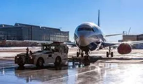
Fig: Aircraft pulled by a tug (towing vehicle)
Towbarless (TBL) tractors do not use a towbar; they scoop up the nose landing gear and lift it off the ground. This avoids the time penalty of connecting/disconnecting a towbar and entirely removes the cost/complexity of maintaining towbars on the ramp. The tug itself does not need to be particularly massive - the aircraft's nosewheel weight provides the necessary downward force. Lastly, a TBL tug is much shorter (compared to a tug+towbar system) and has only a single pivot point instead of one at either end of the towbar, so it has much simpler and precise control of the aircraft. This is very useful in general aviation settings with a wider variety of aircraft in more confined spaces than their airline counterparts.
Manufacturers of electric TBL tugs offer models capable of moving any aircraft from the smallest single-engine type to narrow-body airliners, military cargo, and airline-sized business jets. Just as specialized towbars are required for a wide range of aircraft, many TBL tugs use adapters that enable the movement of many unique aircraft. The majority of aircraft do not require adapters and can be moved without any special adjustments to the tug. This is in contrast to conventional tugs which often use so-called "universal" towbars which must be adjustable to suit many aircraft types. Electric TBL tugs are gaining popularity among general aviation operators and FBOs as an alternative to gas or diesel-powered conventional tugs. Being electric rather than internal combustion-powered, electric tugs are low-emission which is a major advantage for environmentally-conscious operators; this also enables the tug to be safely operated inside a closed hangar.
5. Take-off power, tire design, rolling resistance, tire pressure, brake forces when landing.
Take-off power
Take-off performance can be predicted using a simple measure of the acceleration of the aircraft along the runway based on force equilibrium.
The forces involved will be,
T – Thrust of propulsion system pushing aircraft along the runway.
D – Aerodynamic Drag of vehicle resisting the aircraft motion.
F – Rolling resistance friction due to the contact of wheels or skids on the ground.
During the take-off run, the imbalance in these forces will produce an acceleration along the runway.
`frac{dV}{dt} = frac{T - D - F}{m}`
where `frac{dV}{dt}` is the acceleration along the runway and m is the mass of the vehicle.
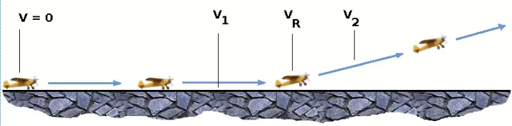
In the figure above,
V1- Abort decision speed. Below this speed, the take-off can be safely aborted. After this, there will not be sufficient runway length to allow the aircraft to decelerate to a stop.
V2 – Safe climb speed. V2 must be no less than 1.2 * Vstall. Below this speed aircraft cannot attain a sufficient climb rate.
The thrust of gas turbines or turbofan engines will be relatively constant during take-off. A good assumption is to use the manufacturer's values for maximum static thrust for take-off calculations.
The thrust of a propeller-driven aircraft can be found from the given shaft horsepower data for the engine and the use of the equations using propeller efficiency.
`T = frac{P_(shaft*eta)}{V}`
Tire Design
When it comes to safety, tires are one of the most important components of aircraft. They help to absorb the shock of landing and provide cushioning. It also provides the necessary traction for braking and stopping an aircraft. An aircraft tire is designed to withstand extremely heavy loads while landing, take off, taxing, and parking. The number of wheels required for aircraft increases with the weight of the aircraft, as the weight of the airplane needs to be distributed more evenly. A Boeing 737NG & 737MAX uses 6 wheels, Boeing 787 uses 10 wheels, Boeing 777 uses 14 wheels and Airbus A380 uses 22 wheels. Aircraft tires work under extreme conditions, carrying up to 340 tons and accelerating at over 250 km/hour at takeoff, in addition to enduring varied environmental stress when in flight and taxiing.
Design and Construction of Aircraft Tyre
Carcass plies are used to form the tire. They are sometimes called casing plies. An aircraft tire is constructed for the purpose it serves.
- They support the weight of an aircraft while it is on the ground.
- It also provides the necessary traction for braking and stopping an airplane.
- Tyre also helps to absorb the shock of landing and provides cushioning for the roughness of takeoff, roll-out, and taxi operations.
Unlike an automobile or truck tire, it does not have to carry a load for a long period of continuous operation. However, an aircraft tire absorbs the high impact loads of landing, and also it’s operating at high speeds for a short time when required.
Fig: Parts of tire
Tubeless tires are more advantageous over tube-type. There is no longer the use of tube-type tires in recent aviation. Nowadays all airliners are using tubeless tires. Tubeless that are meant to be used without a tube has the word TUBELESS on the sidewall of the tire. Almost all airliners are using Radial tires. Bias is an older design, and it’s mainly used for road vehicles. Radial tires have the word RADIAL on the sidewall. Radial tires are more expensive than bias-ply tires. Radial tires are in demand because of their lower life cycle cost and long term value. Today’s tires are conductive. Aircraft tires are manufactured with tread rubber with conducting compounds to permit the earthing of static charges.
Rolling Resistance
The friction between aircraft and runway will be proportional to the normal force exerted by the aircraft on the runway.
`F = mu*(W−L)`
The normal force will be the difference between the Weight of the aircraft and Lift, the friction coefficient will be typical of a magnitude of 0.02 for a standard tarmac runway. The rolling resistance is usually between 0.02 to 0.03 for an aircraft.
Tire Pressure
Aircraft tires generally operate at high pressures, up to 200 psi (14 bar; 1,400 kPa) for airliners, and even higher for business jets. Tests of airliner aircraft tires have shown that they are able to sustain pressures of a maximum of 800 psi (55 bar; 5,500 kPa) before bursting. Aircraft tires are usually inflated with nitrogen to minimize expansion and contraction from extreme changes in ambient temperature and pressure experienced during flight. Dry nitrogen expands at the same rate as other dry atmospheric gases (normal air is about 80% nitrogen), but common compressed air sources may contain moisture, which increases the expansion rate with temperature. Tire pressure depends on the weight of the plane and the number of tires it has, but generally, the cold pressure is between 200 and 300+ psi.
Brake Force
Stopping a heavy aircraft landing at high speed requires a lot of braking force. To do this, the aircraft has one brake unit on each of the eight wheels on the main gear assembly. On other aircraft types, the brake units are powered by the hydraulics system. An electrical signal is sent from the flight deck to hydraulic actuators near the main landing gear. Here, hydraulic fluid at 3,000 pounds per square inch is used to force the brake unit against the wheel, thus slowing it down. This system works fine, but the pipes and actuators that form this part of the hydraulic system come at a considerable weight cost. Extra weight means more fuel burn, which in turn increases costs and carbon emissions. The different brakes used in this case are electric brake, anti-skid protection, auto brake, parking brake. For the purpose of braking spoilers and reverse thrust are also used.
The touch-down velocity should be approximately the stall speed of the aircraft in the landing configuration. This will 82be achieved by a pitch maneuver during the flare portion of the approach which increases drag and decelerates the aircraft to minimum flying speed. The deceleration on the landing roll from VTD to V0 will be accomplished by braking and reverse thrust. This can be solved by the average acceleration approach that was used to estimate the take-off roll.
`frac{dV}{dt} = frac{-T - D - F}{m}`
The negative acceleration or deceleration value will be based on the friction coefficient for maximum braking and the value of reverse thrust.
6. Calculating the force and power required to push/pull an aircraft by a towing vehicle
Let's consider the Boeing 757, a medium weight aircraft.
Co-efficient of Rolling Resistance = 0.028
Weight of the aircraft = 99790 kg
The frontal area of aircraft = 185 `m^2`
The tug that is used to pull it to the runway is TLD TMX 150.
Co-efficient of Rolling Resistance = 0.9
Weight of the tug = 8291 kg
The frontal area of tug = 24 `m^2`
Speed of both aircraft and tug while pulling it to the runway is 10 km/h, which is 2.77 m/s.
Gear Ratio for torque requirement = 0.25
The radius of the tug tire = 411 mm
The equation to calculate forces are;
Force due to rolling resistance `(F_r) = mu_(rr)*m*g`
Drag force `(F_d) = frac{1}{2}*C_d*rho*A*V^2`
Total force `(F) = F_r + F_d`
The relationship between torque and force is;
`F = T*frac{G}{r}`
To implement the calculation, we will use a Simulink block
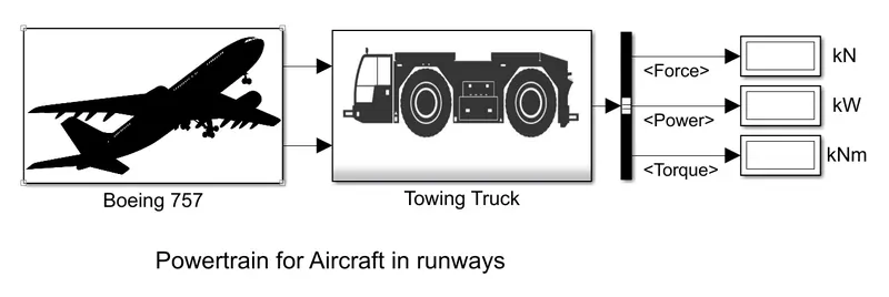
Simulink model to calculate the force required to pull aircraft
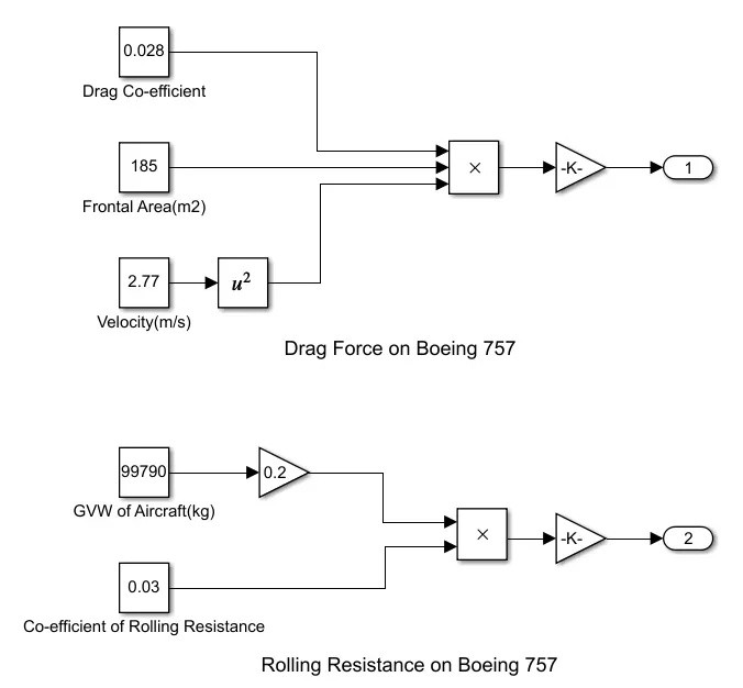
Forces on Aircraft
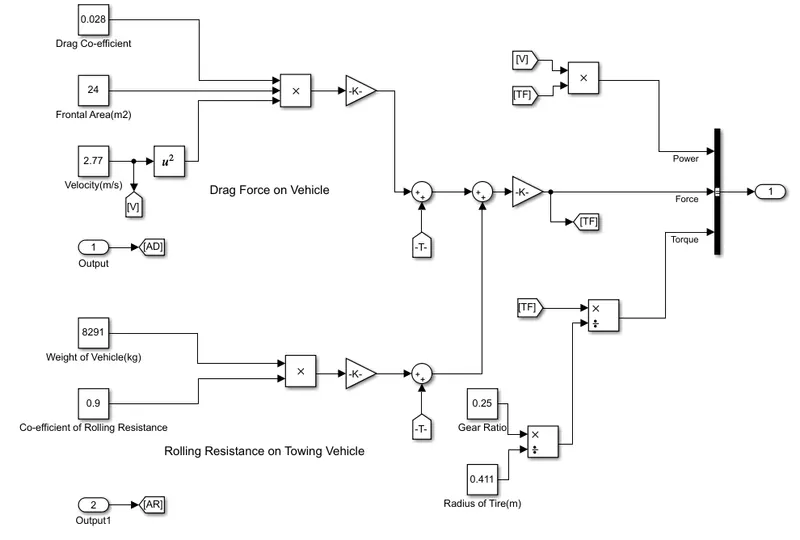
Forces on towing the vehicle to pull aircraft
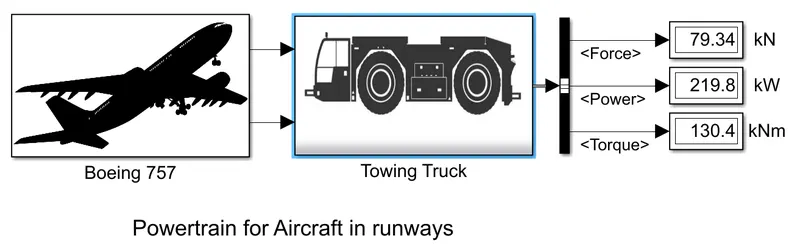
Required Total Force, Power, and Torque
7. Electric powertrain with block diagram
For such a power requirement a motor should have a higher power.
The following is the roughly created electric powertrain for the above requirement.
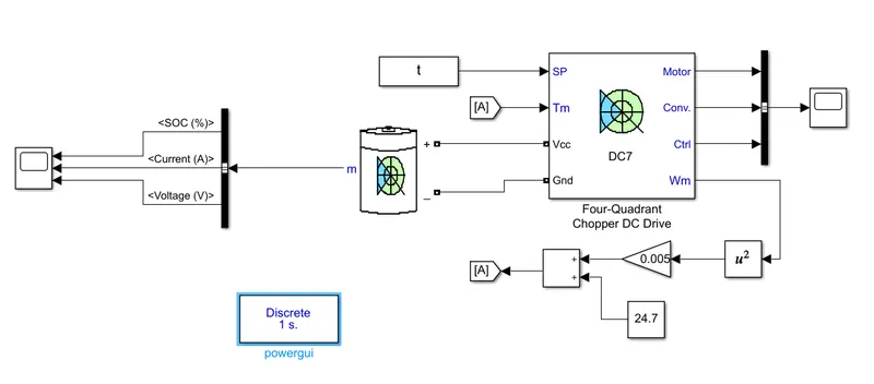
Fig: Roughly modeled Electric powertrain
Let's say the motor is 80 % efficient. Then the rated power should be 275 kW
The battery pack has an overall voltage of 400 V
The current requirement is 275000/400 = 687.5 A
The DC drive has a built-in Motor, Converter, Controller as well as PWM for duty cycle
The following Torque - Speed relation is used for feedback;
`T = 24.7 + 0.0051*omega^2`
Note: The above created is roughly made Electric Powertrain
Below is the block diagram of the powertrain:
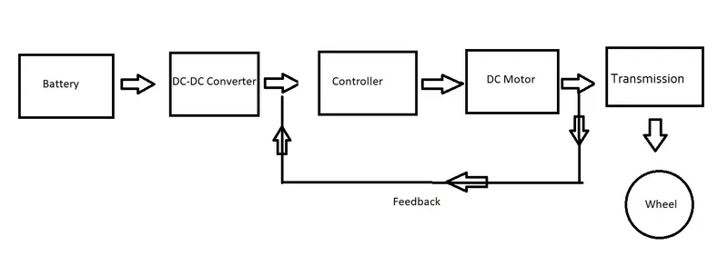
Block diagram of Electric Powertrain (Tug)
The current at a certain voltage is drawn from the battery. Then using the Boost Converter we step up the voltage. The Controller with the use of Pulse Width Modulation gives the signal for switching the motor. DC motor runs with a certain speed and torque. This torque needs to be increased. As a result, the transmission is used for this purpose. In this case, Planetary gears are used. Then the torque is given to the wheel. The Speed of the motor gives feedback to the control to adjust the duty cycle to run the motor accordingly.
Reference:
http://www.boeing.com/commercial/aeromagazine/aero_06/textonly/s02txt.html