Project 1 - MODELLING, ANALYSIS & DESIGN OF TALL BUILDINGS IN ETABS
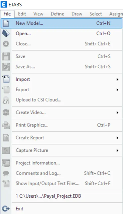
Navigate to the ETABS software, click on the "File" option in the menu, and then select "New Model" from the available choices, following the steps depicted in the provided image.
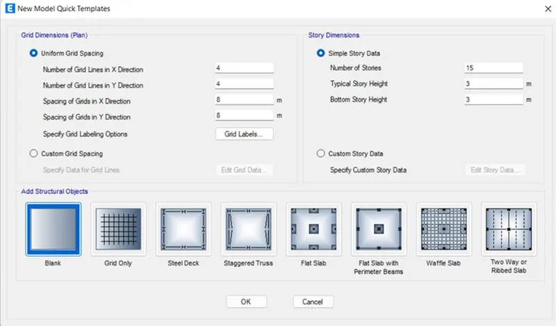
To import the AutoCAD architectural file into ETABS, follow these steps:
Save the AutoCAD file as a .dxf format.
Open the ETABS software, then go to the "File" option in the top menu.
From the drop-down list, select "Import."
Another drop-down list will appear. Choose the option labeled ".dxf file of the floor plan."
These steps are illustrated in the provided image for your reference.
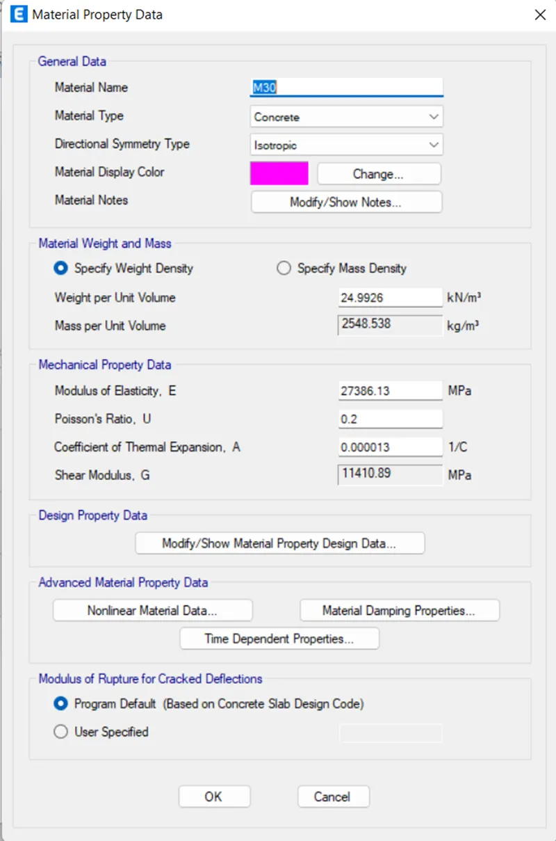
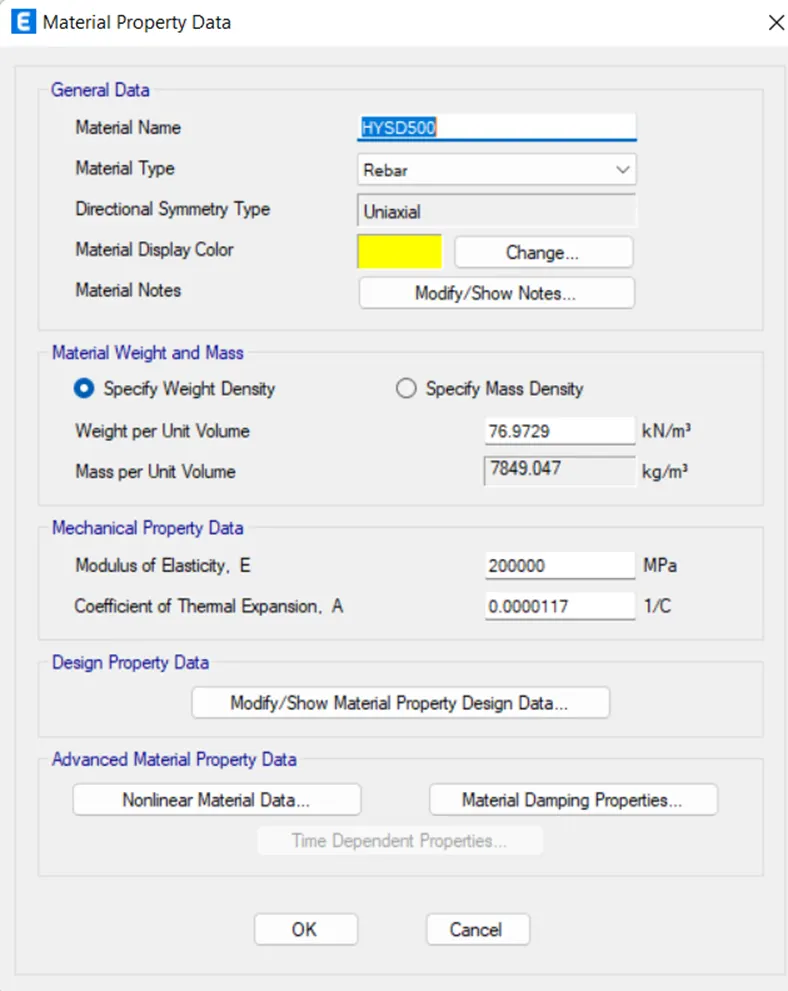
To create properties for slabs, beams, columns, and walls for use in the project, follow these steps:
- Start by defining the properties for a beam with dimensions 400X500:
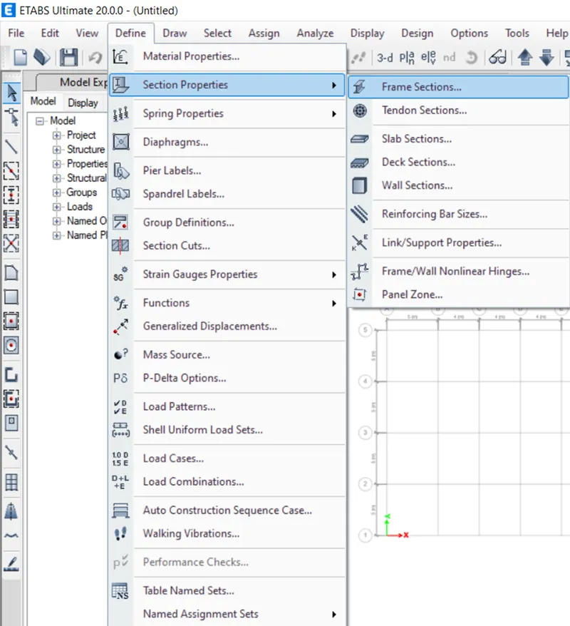
- Click on the "Define" option in the software.
- From the resulting drop-down list, select "Section Properties."
- Another drop-down list will appear; choose the option "Frame Section."
- These steps are visually represented in the provided image for your reference.
Next, a dialogue box labeled "Frame Properties" will appear. Within this dialogue box, you will find an option named "Add New Property." Simply click on this option, mirroring the procedure depicted in the provided image.
BEAM
COLUMN
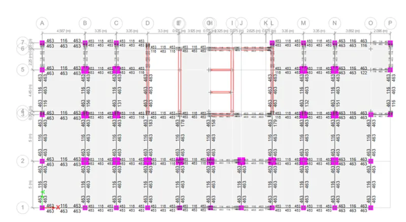
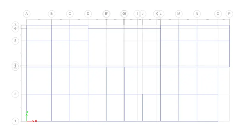
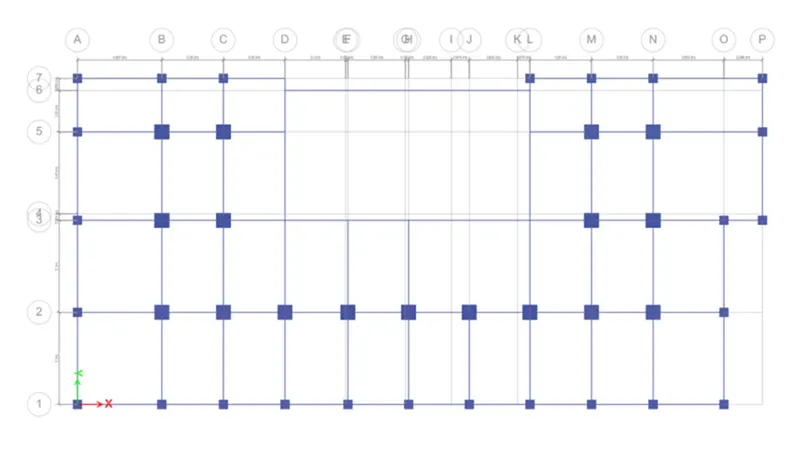
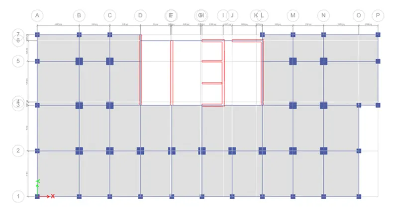
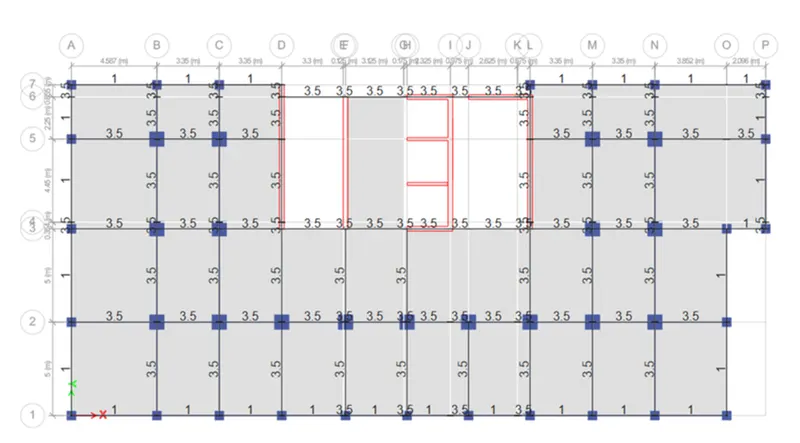
Model typical floor plate using shell & frame elements as indicated in architectural plan
SLAB
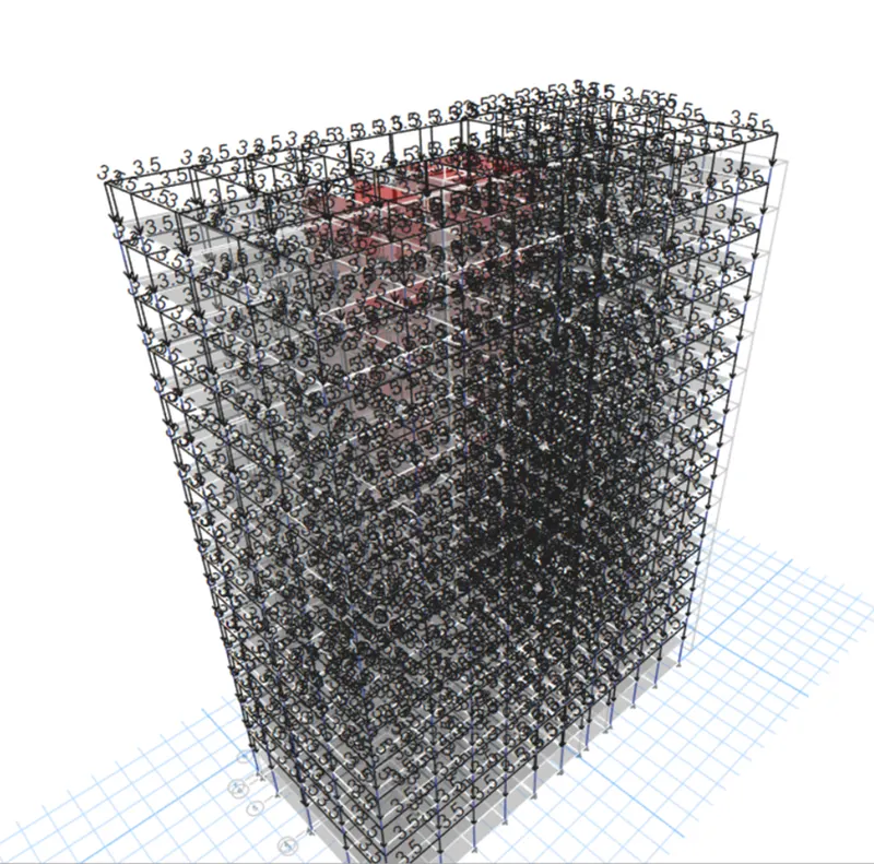
To assign the floor finish, proceed as follows:
- Access the "Assign" option in the software interface.
- In the resulting drop-down list, locate and select "Shell Loads."
- Another drop-down list will appear. From this list, choose the "Uniform" option.
This process is visually represented in the provided image for your reference.
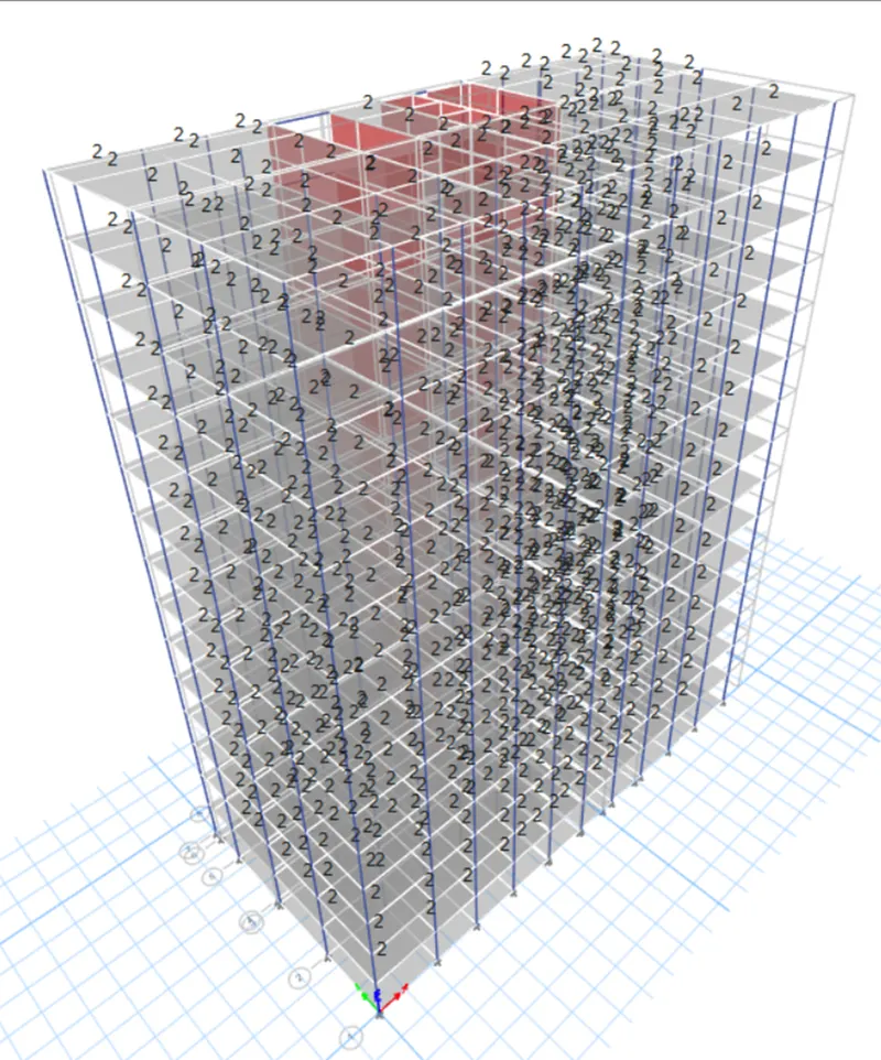
To assign the Live Load, follow these steps:
- Click on the "Assign" option within the software interface.
- From the subsequent drop-down list, select "Shell Loads."
- In the ensuing drop-down list, opt for the "Uniform" option.
For a visual reference, consult the image provided above.
To define the mass source for earthquake loads, perform the following steps:
- Navigate to the "Define" tab and select it.
- A drop-down list will appear. From this list, choose the option labeled "Mass Source."
For a visual representation, refer to the provided image above.
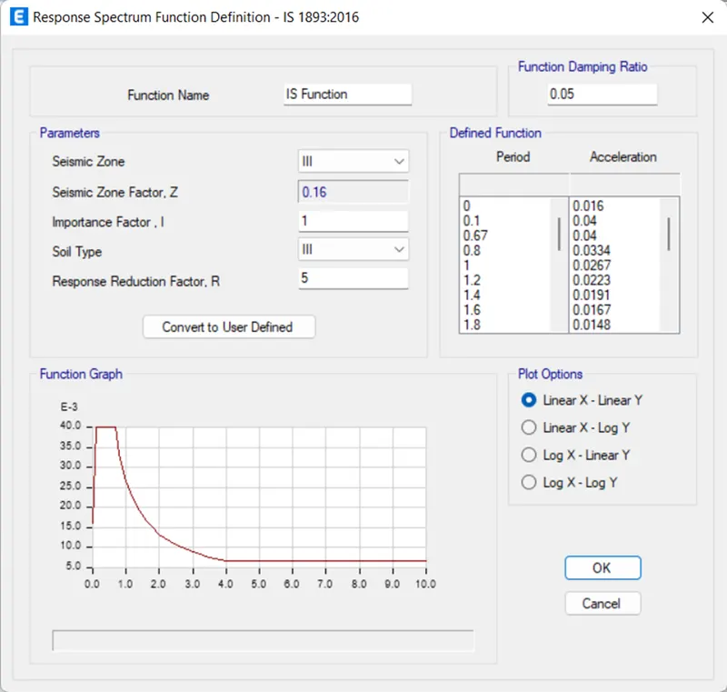
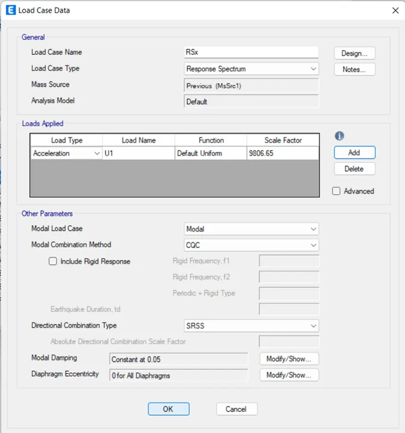
To add the Response Spectrum in load cases as RSx and RSy, follow these steps:
- Access the "Define" tab by clicking on it.
- In the resulting drop-down list, locate and select "Load Cases."
For a visual guide, consult the provided image above.
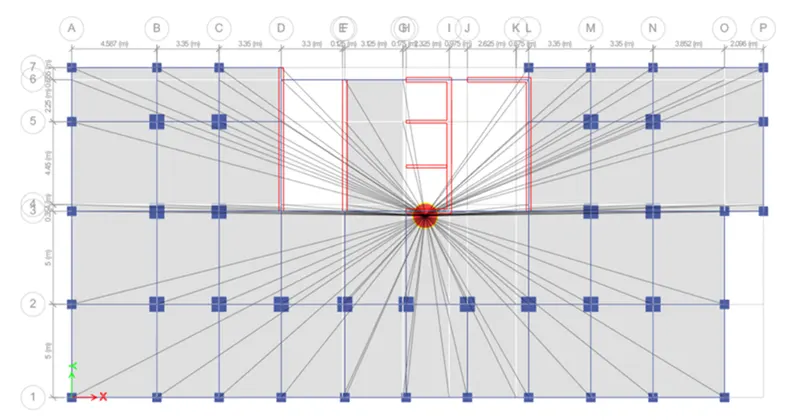
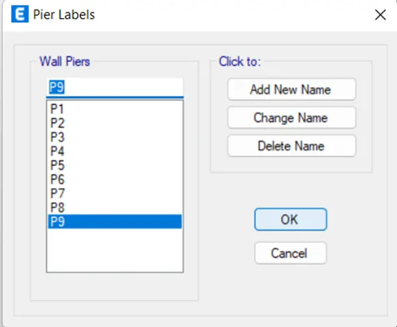
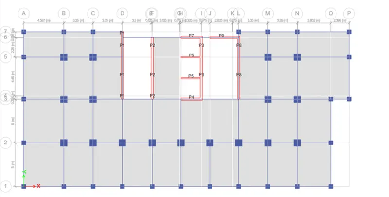
Subsequently, assign the support condition as a fixed support, mirroring the steps depicted in the provided image:
- Select the desired element or node.
- Access the "Support Conditions" option.
- Set the support condition to "Fixed Support."
For a visual representation, refer to the image provided above.
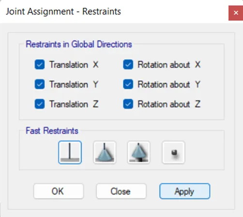
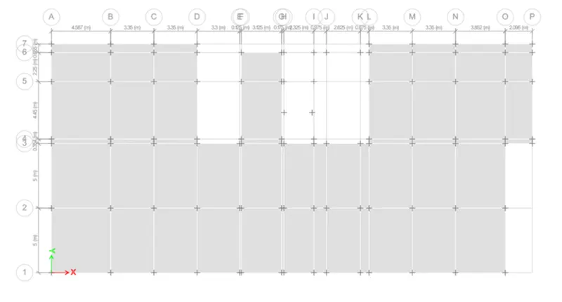
To create service and ultimate load combinations according to IS 456:2000, follow these steps:
- Navigate to the "Define" tab and select it.
- From the resulting drop-down list, choose the option labeled "Load Combinations."
For a visual reference, consult the provided image below.
Perform quick hand calculations to confirm the base reactions for the gravity load cases:
Slab thickness = 150mm
Beam size= 300mm X 300mm
Live load = 2 kN/sq.m.
Floor finish= 1.5 kN sq.m.
Brickwall load= 3.5 kN/m.
Self weight of slab = 0.150 X 25 KN/m2 = 3.75 kN/sq.m.
Total load in slab = 3.75 + 2 + 1.5 = 7.25 kN/sq.m.
Load in each end of B1:-
Area 2(Trapezoidal area):
A1 = 1/2 * (1.529 + 4.587) * 2.5 = 7.645 sq.m.
Bay width of B2 = A1/L or L/4
= 7.645/4.587 = 1.66 m or 1.14m
UDL transferred from slab-1 to Beam-2 = B.W X Slab-2 load
= 1.66 X 7.25 = 12.035 kN/m
Beam-1 Self weight = 0.4*0.4*25 = 4 kN/sq.m.
Total UDL on B1 = 4 + 12.035 + 3.5 = 19.535 kN/m.
Total load on B1 = (19.535 X 4.857) = 89.607 kN.
Load on each end for B1 is 44.804 kN.
Load in each end of B2:-
Area 2(Triangular area)
A2 = [1/2 * 2.5 * 1.529 ]* 2 = 3.82 sq.m.
Bay width of B2 = A2/L or L/4
= 3.82/5 = 0.764 m or 1.25m
UDL transferred from slab-2 to Beam-2 = B.W X Slab-2 load
= 1.25 X 7.25 = 9.0625 kN/m.
Beam-1 Self weight = 0.4*0.4*25 = 4 kN/sq.m.
Total UDL on B2 = 4 + 9.0625 + 3.5 = 16.5625 kN/m
Total load on B2 = (16.5625 X 5) = 82.82 kN
Load on each beam B2= 41.41 kN
Total axial load on column C1 = 44.804 + 41.41 = 86.21 KN
Total axial load on C1 column = Number of floor X Load in first floor Column C1
= 15 X 86.21 = 1293.15 kN.
- Design of structural members
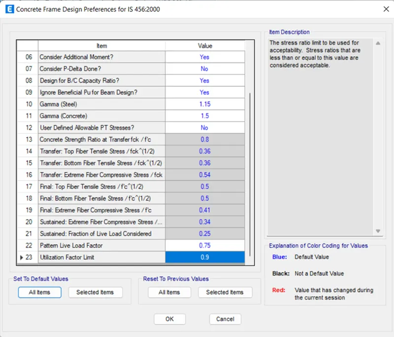
Select appropriate parameters for the design of the members.
Interpret the design results.
Re-design and restrict the member utilization within 0.9.
Identify the reinforcement requirements for each structural member.