Project-1: Modelling an electric Car with Li-ion battery
Aim:
To create a SIMULINK model of an electric vehicle (EV) that is powered by a lithium-ion battery with speed control implementation using a PID controller.Create a MATLAB model of electric car which uses lithium-ion battery and suitable motor. Choose suitable blocks from Simscape or Powertrain block set. Implement the vehicle speed control using PI controller and generate brake and accelerator commands. Avoid using readymade driver block for speed control.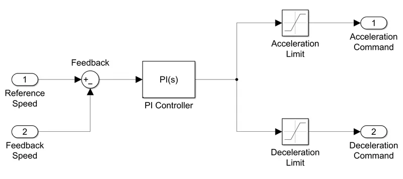
In this project, I will model an EV in SIMULINK using the powertrain blockset and simscape blocks. This model will implement speed control using a PID controller block. The input to this model will be a Wide Open Throttle (WOT) drive cycle. The output of this model will be blocks that show the total distance travelled by the model and the speed of the vehicle during a 30 second simulation period. The speed data will reflect both the actual speed of the vehicle and the command speed from the drive cycle data.
System Level Configuration:
To model the EV in SIMULINK, we need to model the individual components of an EV such as the motor, controller, power converters, wheels, and batteries. All of these components are available as blocks from the simscape and powertrain blocksets. The various components of the EV will be modelled and explained in the sections below:
Wind Velocity & Slope
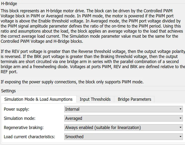
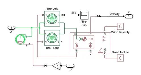
From the "W" and "beta" ports on the vehicle body block, I have used a "PS-Constant" block to model the effect of the wind velocity and the slope.
Velocity Subsystem
From the "V" port on the vehicle body bock, I have created a subsystem. This is because by default, this port will output the vehicle speed in miles per hour. For personal preference, I have created the subsystem to get the output speed in kilometres per hour. This system consists of a PS-Simulink converter block, a gain block, and a zero-order hold block. The gain block uses a factor of 1.6 to convert the speed from miles per hour to kilometres per hour. The PS-Simulink converter block is used to convert the physical signal of speed to a SIMULINK signal to be displayed on the scope block.
- Current Sensor:
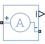
- This block is used to measure the flow of current through a circuit.
Motor Subsystem:
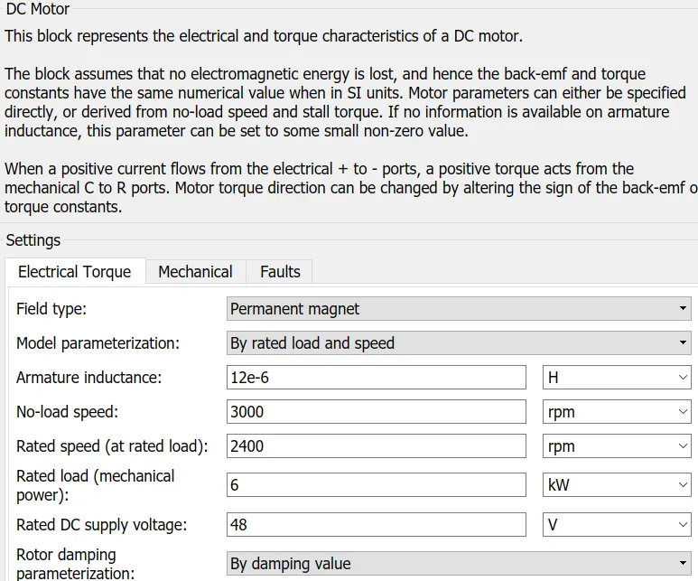
- DC motor:
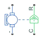
- To convert the electrical energy to mechanical energy we use motors. In this electric vehicle model, we have used DC motor. This motor can act as a generator also in case of regenerative braking.
- Ideal Rotational Motion Sensor Block:

- the output from this block is in rad/sec. so, unit conversion is done in ps-simulink converter block.
Battery Subsystem:
- Controlled Current Source:
- The Controlled Current Source block converts the Simulink input signal into an equivalent current source. The generated current is driven by the input signal of the block.
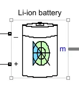
- Li-ion battery:
-
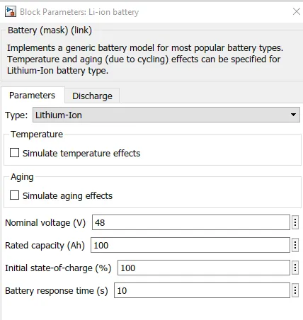
- The Battery block implements a generic dynamic model that represents most popular types of rechargeable batteries.
Vehicle Body Subsystem:
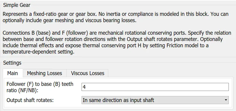
- Fixed Gear:
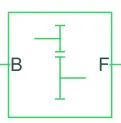
- The Simple Gear block represents a gearbox that constrains the connected driveline axes of the base gear, B, and the follower gear, F, to corotate with a fixed ratio that is specified.
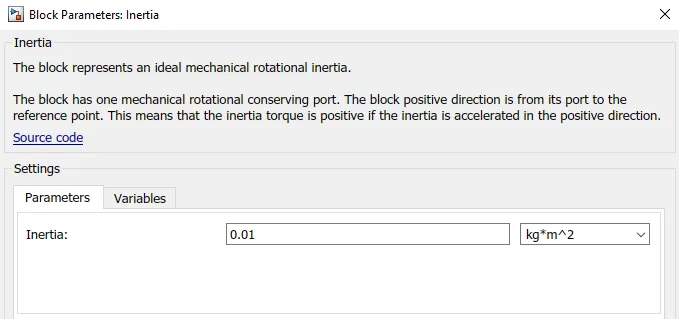
- Inertia:

- The Inertia block represents an ideal mechanical rotational inertia.
- Tire (Magic Formula):
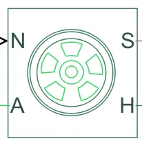
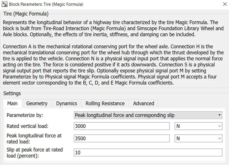
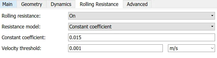
- The Tire (Magic Formula) block models a tire with longitudinal behavior given by the Magic Formula an empirical equation based on four fitting coefficients. The block can model tire dynamics under constant or variable pavement conditions.

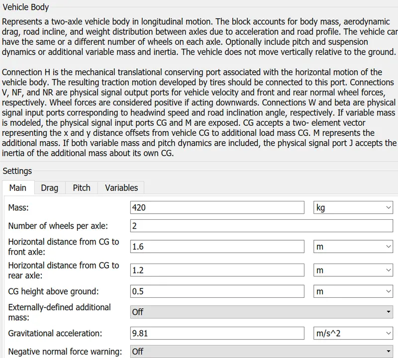
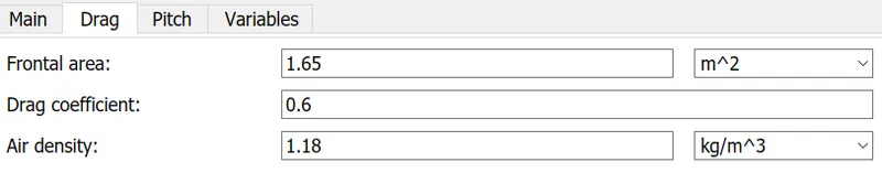
- Vehicle Body:
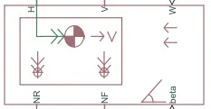
- The Vehicle Body block represents a two-axle vehicle body in longitudinal motion. The vehicle can have the same or a different number of wheels on each axle. For example, two wheels on the front axle and one wheel on the rear axle. The vehicle wheels are assumed identical in size. The vehicle can also have a center of gravity (CG) that is at or below the plane of travel.
- The block accounts for body mass, aerodynamic drag, road incline, and weight distribution between axles due to acceleration and road profile. Optionally include pitch and suspension dynamics. The vehicle does not move vertically relative to the ground.
- The block has an option to include an externally-defined mass and an externally-defined inertia. The mass, inertia, and center of gravity of the vehicle body can vary over the course of simulation in response to system changes.
- Vehicle Body:
-
- The Vehicle Body block represents a two-axle vehicle body in longitudinal motion. The vehicle can have the same or a different number of wheels on each axle. For example, two wheels on the front axle and one wheel on the rear axle. The vehicle wheels are assumed identical in size. The vehicle can also have a center of gravity (CG) that is at or below the plane of travel.
- The block accounts for body mass, aerodynamic drag, road incline, and weight distribution between axles due to acceleration and road profile. Optionally include pitch and suspension dynamics. The vehicle does not move vertically relative to the ground.
- The block has an option to include an externally-defined mass and an externally-defined inertia. The mass, inertia, and center of gravity of the vehicle body can vary over the course of simulation in response to system changes.
Battery System
The battery system is an essential part of the EV model as it will provide the electrical power required to power the DC motor. The components of the battery system are explained below:
Battery
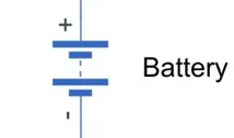
The battery block used is a simple one and considers only the basic parameters. The battery block is shown below:
Double-clicking the battery block, opens the block parameters which is shown in the image below:
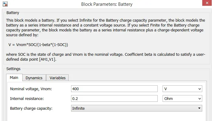
As we can see, the battery block parameters include the nominal voltage, the internal resistance and the battery charge capacity. I have used a nominal voltage of 400V, an internal resistance of 0.2 Ohms and an infinite battery charge capacity.
Drive Control
In order to control the vehicle, we need another system that decides how the vehicle will operate. This means that data needs to be input in to this model as commands for how we desire the vehicle to operate. In addition, we need blocks that control how the vehicle will operate as a response to its instantaneous state. This system is explained below:
Drive Cycle
A drive cycle is a data set that contains velocity and time data for the purpose of modelling the motion of a vehicle. The drive cycle will be a plot of the velocity against the time and it is made to resemble typical driving conditions that a consumer may experience themselves in. For instance, they can model highway driving situations, driving in urban areas, or driving with full power etc.
In my EV model, a drive cycle is used as the reference velocity data for the longitudinal driver block to send acceleration or deceleration commands according to the drive cycle. There are 3 ways of implementing a drive cycle. One method is to create or own drive cycle with a spreadsheet of velocity data in one column and time data in another column. Another method is to use a signal builder block and create signals that represent the velocities at which the vehicle should travel and the durations for which those velocities are to be maintained. The last method is to use the industry standard drive cycles which are in - built in to the SIMULINK library. In my case, I have used an industry standard 'WOT' drive cycle. This drive cycle stands for 'Wide Open Throttle' and it models the situation where the vehicle is made to accelerate at full power and maintained at a particular speed and made to decelerate back to rest.
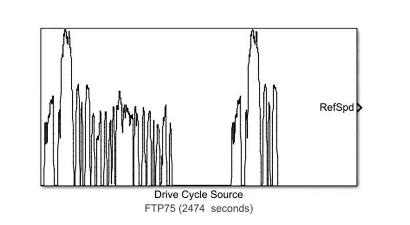
This can be modified by opening the block parameters shown below:
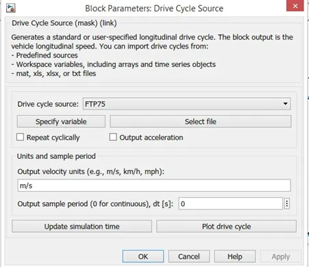
When the 'WOT' drive cycle is chosen, some extra parameters are made available for modification which are shown below:
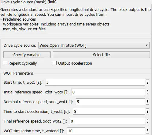
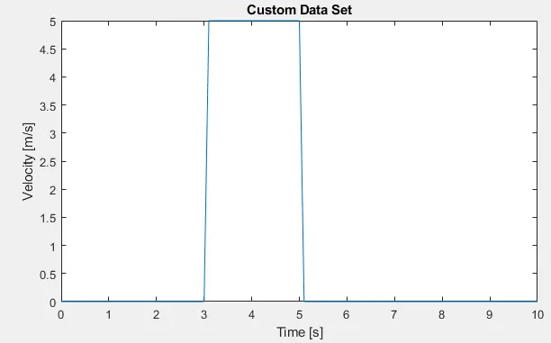
As we can see, with the 'WOT' drive cycle, we can modify the start time, time to start deceleration, and the entire duration of the drive cycle. I have used a start time of 3 seconds meaning that the vehicle will begin acceleration after 3 seconds of starting simulation. I have used a nominal reference speed of 5 m/s and this refers to the maximum speed the vehicle should achieve. I have set the deceleration to begin at t = 5 seconds and the whole cycle is set for a duration of 10 seconds. The input and output velocity units are both set to m/s.
The plot below shows the custom WOT drive cycle I have created.
Result Plot:
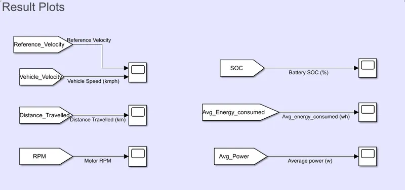
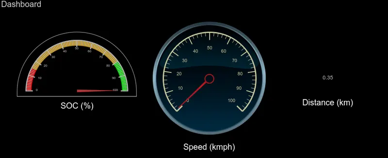
Reference Velocity vs Vehicle Velocity:
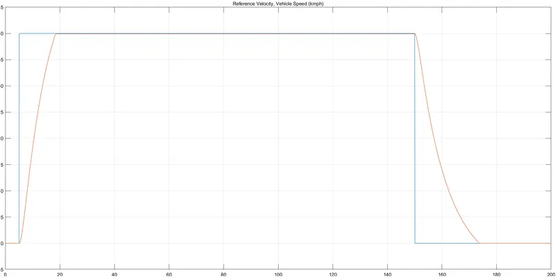
As per above plot, we can see 0 - 40kmph is achieved in 14sec.
Distance Travelled (km):
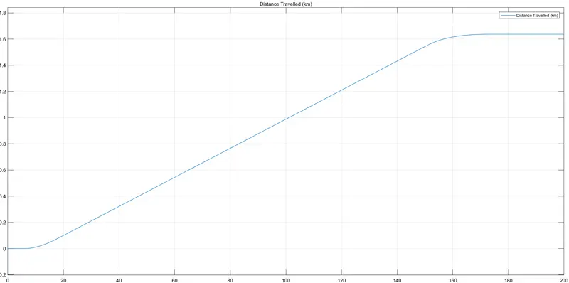
Distance Travelled is 1.64km
Motor RPM:
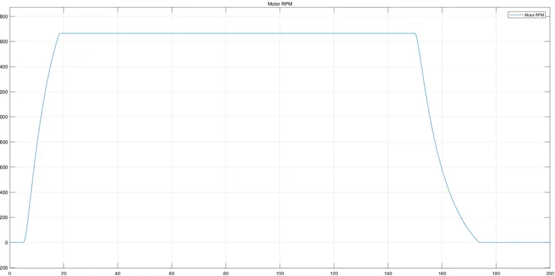
SOC (%):
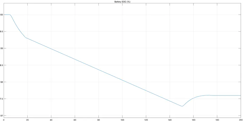
Battery SOC dropped to 97.25%
Average Energy Consumed (wH):
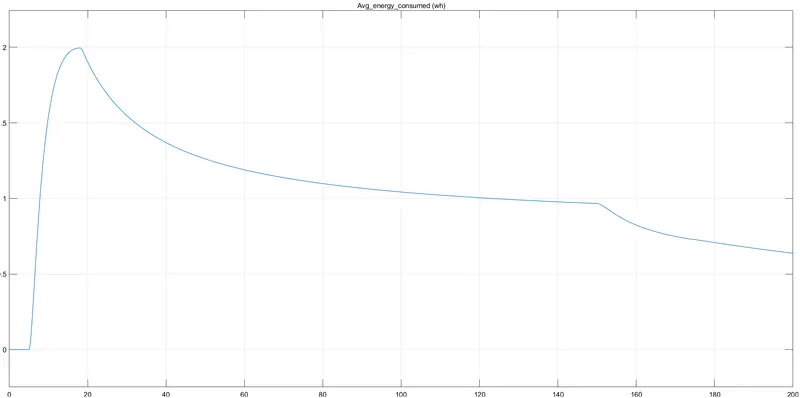
Average Power Consumed (kW):
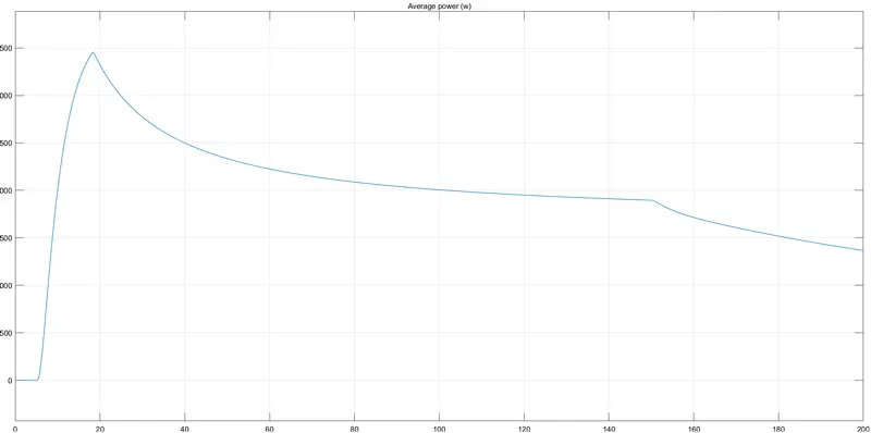
Conclusion
In conclusion, the vehicle speed was controlled to some extent with the implementation of the PID controller block. Since this was not a linearized system, the auto-tune feature in the PID controller block could not be used. Trial and error was performed in a few attempts to control the speed of the vehicle to match the drive cycle reference speed more closely. Despite being able to manually tune the PID controller, the vehicle speed was still unable to reach the desired peak speed value of 5 m/s from the drive cycle. In addition, the vehicle was also unable to sustain said peak speed value from the drive cycle for the desired time period of 2 seconds.
MATLAB model of electric car which uses lithium-ion battery and suitable motor is created.