Project-1: Modelling an electric Car with Li-ion battery
YOUR ANSWER:
Aim:
To Create a MATLAB model of an electric car in which we uses which uses lithium ion battery and suitable motor choosing a suitable blocks from the Powertrain block set and Implement the Vehicle Speed by using PI Controller and generate the accelerator and brake commands.
Objectives:
To prepare the technical report about the EV model including
- System level configurations
- Model parameters
- Results
- Conclusion
Theory:
An electric car is powered by the electric motor instead of a petrol engine. The electric motor gets energy from the controller, which regulates the amount of powerbased on the driver’s use of an accelerator pedal. The electric car (also known as electric vehicle or EV) uses the energy stored in its rechargeable batteries, which it recharged by common household electricity.
Thus an electric vehicle will have three basic components :
- Energy Storage Unit
- Controller
- Propulsion system
The energy storage unit will have a way to store power. The controller acts as a pipeline or gateway to the electric motor. The controller acts like brains of the system.The electric motor, which is the propulsion system, converts the electric power and converts this into physical energy for movement. The whole system is a much simpler, more efficient device than the combustion engine found in most cars, enabling you to get the most mileage for your charge.

Electric Vehicle Components
Basic Main Components of Electrical Vehicle:
The basic main elements of electric cars installed in almost all types of electric cars are as follows:
Traction Battery Pack:
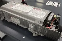
- The function of the battery in an electric car is to energy storage system in the form of (DC). If it gets a signal from controller, the battery will flow DC electrical energy to the inverter and then be used to drive the motor. The type of battery used is rechargeable battery that is arranged in such a way as to form what is called a traction battery pack.
- There are various types of electric car batteries. The most widely used is the type of lithium-ion batteries.
Power Inverter:
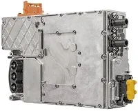
- The inverter functions to change the direct current (DC) on the battery into an alternating current (AC) this alternating current is used by an electric motor. In addition to the inverter on an electric car also has a function to change the AC current when regenerative braking to DC current and then used to recharge the battery. This type of inverter used in some electric car models is the bi-directional inverter category.
Controller:
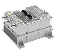
- The main function of the controller is as a regulator of electrical energy from batteries and inverters that will be distributed to electric motors. While the controller itself gets the main input from the car pedal (which is set by the driver). This pedal setting will determine the frequency variation or voltage variation that will enter the motor, and at the same time determine the car’s speed.
Electrical Traction Motor:
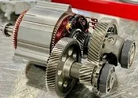
- Because the controller provides electrical power from the traction battery, the electric traction motors will work turning the transmission and also to wheels. Some hybrid electric cars use a type of generator-motor that performs the functions of propulsion and regeneration.
Other Electric Car Components:
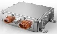
Charger
This is a battery charging device. Chargers get electricity from outside sources. AC electricity is converted into DC electricity and then stored in the battery.
There are 2 types of electric car chargers:
- On-board charger: the charger is located and installed in the car(inside the car)
- Off-board charger: the charger is not located or not installed in the car (outside the car)
Transmission :
The transmission transfers mechanical power from the electric traction motor to drive the wheels.
DC/DC Converter:
This one of electric car parts that to converts higher-voltage DC power from the traction battery pack to the lower-voltage DC power needed to run vehicle accessories and recharge the auxiliary battery.
Battery :
In an electric drive vehicle, the auxiliary battery provides electricity to power vehicle accessories.
Thermal System – Cooling :
This system maintains a proper operating temperature range of the engine, electric motor, power electronics, and other components.
Charge Port :
The charge port allows the vehicle to connect to an external power supply in order to charge the traction battery pack.
Procedure:
Vehicle Body Subsystem:
The Vehicle is assumed to be the front axle driven( 4 wheels and in 2 on each axle)
Tire
- The Tire (Magic Formula) block models a tire with longitudinal behavior given by the Magic Formula, an empirical equation based on four fitting coefficients. The block can model tire dynamics under constant or variable pavement conditions.
- The longitudinal direction of the tire is the same as its direction of motion as it rolls on pavement.
- To increase the fidelity of the tire model, you can specify properties such as tire compliance, inertia, and rolling resistance. However, these properties increase the complexity of the tire model and can slow down simulation. Consider ignoring tire compliance and inertia if simulating the model in real time or if preparing the model for hardware-in-the-loop (HIL) simulation
The wheels are modelled using simple Tire( Magical formula) simulink blocks.
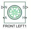
- The N port of the tire corresponds to the Normal Reaction acting on it.
- The A port corresponds to the Mechanical Rotational Conserving Port for the four wheel axle.Thus both the wheels on the same axle should form a connection through their respective A ports
- Connection H corresponds to the Mechanical Translational Conserving Port for the Wheel hub through which the thrust developed by the tire is applied to the vehicle.Thus, all the four wheels form a connection through their respective H ports and thus in turn connected to the translationa; hub of the vehicle body.
The connection S represent the output port for the slip of the tire.
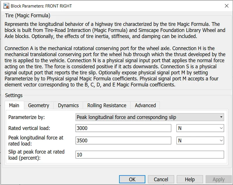
- The tires are parameterized by the peak longitudinal force and corresponding slip.
- The other block parameter such as rated vertical load, peak longitudinal force at rated load and slip at peak force at rated load are kept with their default values.
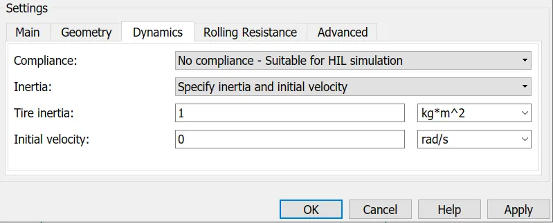
- The tire radius is given as 0.3m.
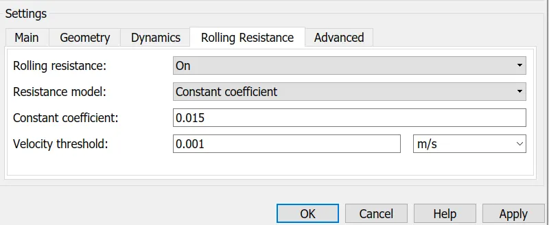
- The tire inertia is kept as 1 kg-m^2. Also the rolling resistance is given with a constant coefficient of 0.015
Velocity Body:
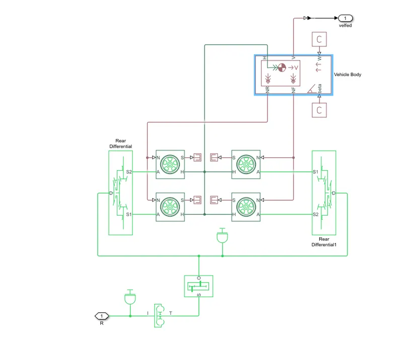
This 2 axle (4 wheel) assembly is now connected to a velocity Body simscape block.
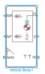
This block basically represent a two-axle vehicle body in longitudinal motion.The block accounts for
- Body mass
- aerodynamic drag
- Road incline
- Weight distribution between axles due to acceleration
- Road Profile.
Here the connection H is the mechanical translational conserving port NF and Nr are said to be a normal reaction forces on the front axle and the rear wheels respectively.Connection V represent the actual output translational velocity of the vehicle.
- Beta is the road inclinational angle and W corresponds to the headwind speed (headwind-direction opposite to that of the vehice)
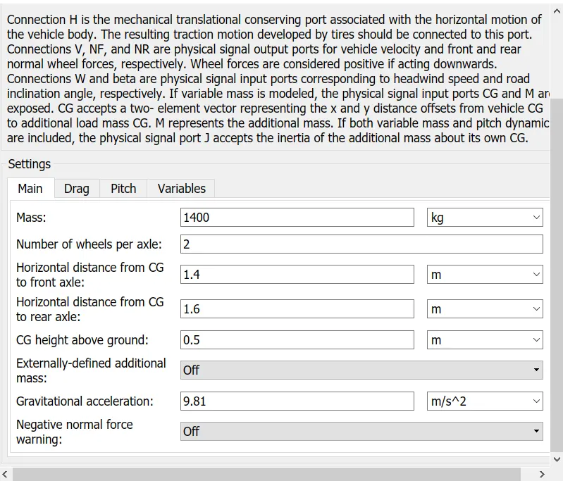
- The gross weight is given to be 800Kg
The geometric paramerters of the vehicle is given as
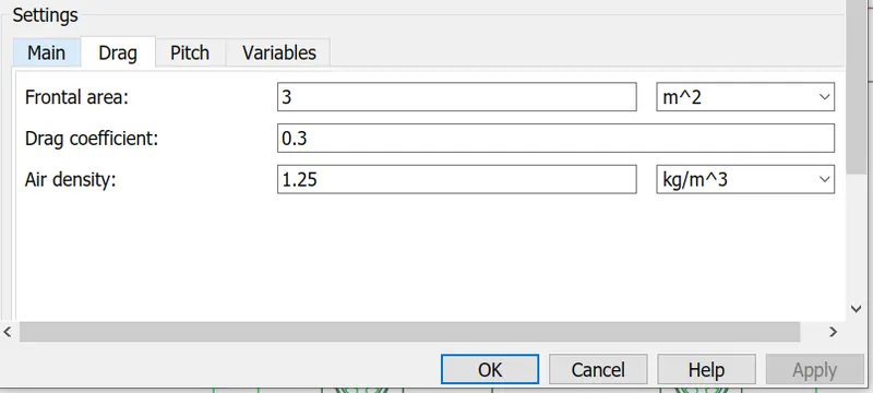
To be account for proper drag force on the vehicle, the related parameters are kept as
The pitch dynamics for the vehicle are not considered for this simulation
Differential:

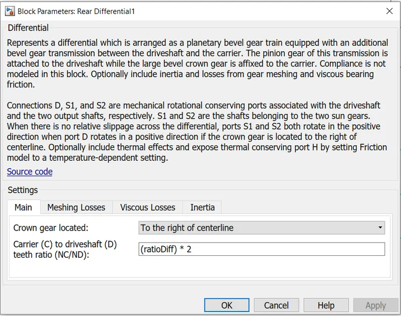
- Gear mechanism that allows driven shafts to spin at different speeds
- The Differential block represents a gear mechanism that allows the driven shafts to spin at different speeds. Differentials are common in automobiles, where they enable the various wheels to spin at different speeds while cornering. Ports D, S1, and S2 represent the longitudinal driveshaft and the sun gear shafts of the differential, respectively. Any one of the shafts can drive the other two.
Simple Gear
- The Simple Gear block represents a gearbox that constrains the connected driveline axes of the base gear, B, and the follower gear, F, to corotate with a fixed ratio that you specify. You choose whether the follower axis rotates in the same or opposite direction as the base axis. If they rotate in the same direction, the angular velocity of the follower, ωF, and the angular velocity of the base, ωB, have the same sign. If they rotate in opposite directions, ωF and ωB have opposite signs.
The input for this subsystem is taken as the Rotational speed of the motor.
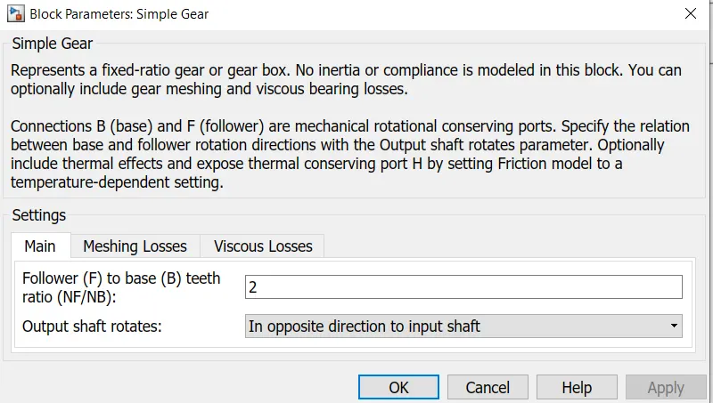
And here the rotational direction of the output shaft is kept as the same as the input shaft. Also, no meshing losses are considered for the simulation.
Inertia:
A concrete block which serves as a base for mechanical equipment such as fans or pumps; the block is mounted on a resilient support to reduce the transmission of vibration to the EV structure.
The complete subsystem is shown below
DC Motor:
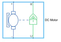
- Simulink Provides an inbuilt model block for a DC motor which converts electrical input into mechanical rotational output.
- Note the blue colour corresponds to the electrical side of the motor and the green colour corresponds to the mechanical side
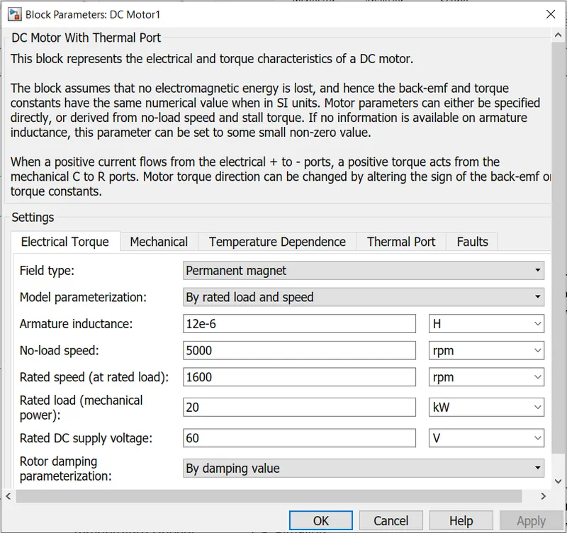
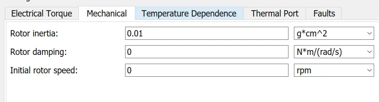
- Here thr motor field type is kept as Permanent magnet and the model parameterization is done by ratedd load and speed. The armature inductance and the mechanical parameters are given as their default values.
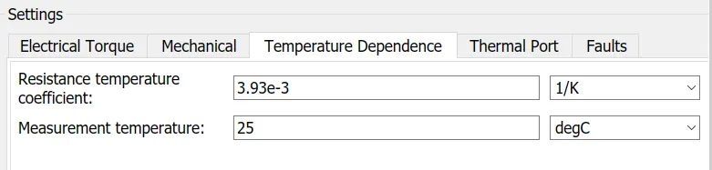
All the other parameters are changed as shoen in below.
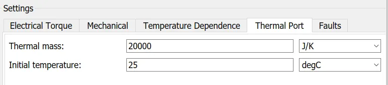
- The connection R represent the Rotor while the connection C is for Casting (stationary).Thus, the R port is connected to the input of the vehicle subsystem created earlier. The C port is connected to a mechanical rotational reference.
- The + and - ve terminal of the motor are connected to the motor controller. If these terminals are directly connected to a battery the required DC motor will run on the rated capacity of the battery. This will eventually resulta into no control over the DC motor and the vehicle will run at the top speed through out the simulation.
We consider the Inertia and the Friction and also the Temperature Sensor.
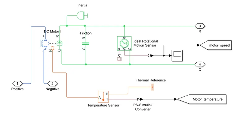
Motor Controller:
H-Bridge circuit:
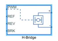
The H-Bridge block represents an H-bridge motor driver. The block has the following two Simulation mode options:
-
PWM— The H-Bridge block output is a controlled voltage that depends on the input signal at the PWM port. If the input signal has a value greater than the Enable threshold voltage parameter value, the H-Bridge block output is on and has a value equal to the value of the Output voltage amplitude parameter. If it has a value less than the Enable threshold voltage parameter value, the block maintains the load circuit using one of the following three Freewheeling mode options:-
Via one semiconductor switch and one freewheeling diode -
Via two freewheeling diodes -
Via two semiconductor switches and one freewheeling diode
The first and third options are sometimes referred to as synchronous operation.
The signal at the REV port determines the polarity of the output. If the value of the signal at the REV port is less than the value of the Reverse threshold voltage parameter, the output has positive polarity; otherwise, it has negative polarity.
-
-
Averaged— This mode has two Load current characteristics options:-
Smoothed -
Unsmoothed or discontinuous
-
The block can be driven by the controlled PWM Voltage block in PWM or Averaged mode.
- In PWM mode, the motor is powered if the PWM port voltage is above the enabled threshold voltage.
- In Averaged mode, the PWM port voltage divided by the PWM signal amplitudes parameter defines that the ratio of on time yo the PWM period.
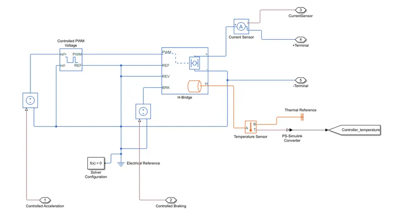
- Connection REF is for the Reference input. This combined with the Pwm connected will form the pulse input for the H Bridge.It is Electrical Reference
- Connection REV corresponds to the reverse motion of the motor which essentially means, the backward motion of the vehicle. Here the backward motion of the vehicle is not accounted for and so the port is connected to the electrical reference.
- Connection BRK is for the braking the Vehicle
- The PWM mode results in a huge amount of simulation time. Averaged mode is selected for this simulation.
- Load current characteristics are considered to be smoothed here.
- The regenerative braking is enabled for the simulation. This means when the vehicle starts decelerating corresponding amount of charge will be fed back to the battery.
- BRK input is connected to a controlled Voltage Source. This will generate emf corresponding to the intensity of brakes applied and fed the power back to the battery.
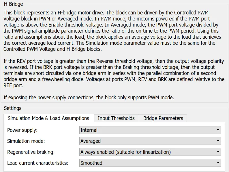
The Input Threshold Parameters are left with their default values.
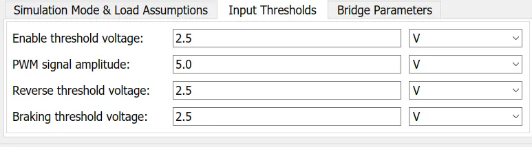
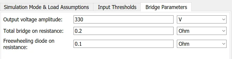
Output Voltage Amplitude of the H-Bridge circuit is given the same value as the rated DC supply Voltage of the DC motor.
Controlled PWM Voltage block
Simulink provides an inbuilt Controlled PWM Voltage block. This block is used for providing the proper pulse input to the block
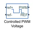
The Controlled PWM Voltage block represents a pulse-width modulated (PWM) voltage source.
-
Electrical input ports — The block calculates the duty cycle based on the reference voltage across its ref+ and ref- ports. This modeling variant is the default.
-
PS input — Specify the duty cycle value directly by using an input physical signal port.
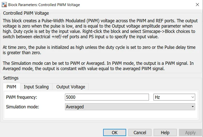
The PWM and REF connection are for the corresponding ports on the H-Bridge Circuit.The two reference inputs corresponds to the throttle inputs given by the driver.The block generates corresponding pulse width as per the acceleration and brakes applied by the driver himself.Here the PWM frquency is 4000Hz. Also the simulation mode is Averaged as that in the H-Bridge circuit.
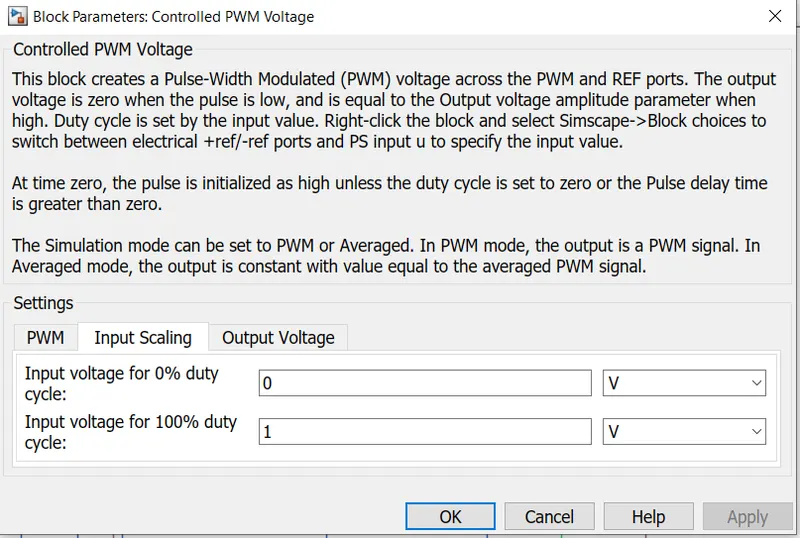
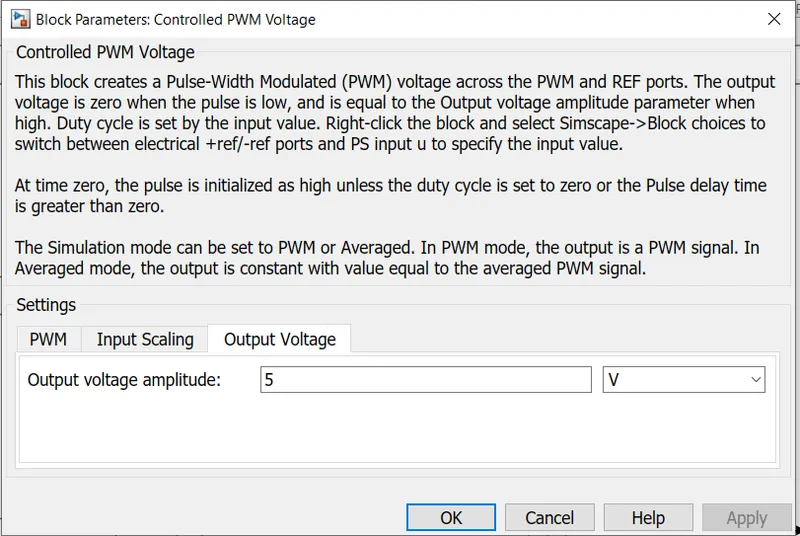
The input Scaling Parameters given are
- 0V for 0% duty cycle and 5V for 100% duty cycle. So the output voltage amplitudes becomes 5V.
The H-Bridge circuit along with the PWM input, together form the motor controller circuit.
PID Controller Subsystem:
The Discrete PID Controller block implements a PID controller (PID, PI, PD, P only, or I only). The block is identical to PID Controller block with the Time domain parameter set to Discrete-time.
The block output is a weighted sum of the input signal, the integral of the input signal, and the derivative of the input signal. The weights are the proportional, integral, and derivative gain parameters. A first-order pole filters the derivative action.
The block supports several controller types and structures. Configurable options in the block include:
-
Controller type (PID, PI, PD, P only, or I only)
-
Controller form (Parallel or Ideal)
-
Time domain (continuous or discrete)
-
Initial conditions and reset trigger
-
Output saturation limits and built-in anti-windup mechanism
-
Signal tracking for bumpless control transfer and multiloop control

The Sum blocks subtract feedback Velocity from the reference Velocity.This output is given to the PID Controller.
The parameters of the PID Controller block is shown in below diagram.
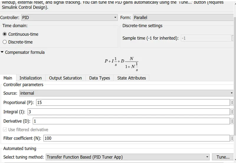
The output from the sum block is given to this block based on the PID, the output is generated.
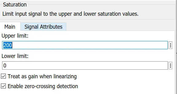
The Saturation block produces an output signal that is the value of the input signal bounded to the upper and lower saturation values. The upper and lower limits are specified by the parameters Upper limit and Lower limit.
| Input | Output |
|---|---|
| Lower limit ≤ Input value ≤ Upper limit | Input value |
| Input value < Lower limit | Lower limit |
| Input value > Upper limit | Upper limit |
In the Saturation there is two types they are
Acceleration:
Deceleration:
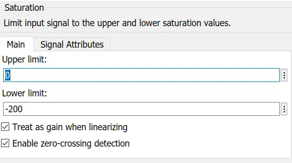
This blocks helps to limit the output signal from the PID controller and the separate deceleration and the acceleration values.
The output from these block is sent to a transfer function then these are provided to the motor Controller block.
Battery:
A lithium-ion (Li-ion) battery is an advanced battery technology that uses lithium ions as a key component of its electrochemistry. During a discharge cycle, lithium atoms in the anode are ionized and separated from their electrons. The lithium ions move from the anode and pass through the electrolyte until they reach the cathode, where they recombine with their electrons and electrically neutralize. The lithium ions are small enough to be able to move through a micro-permeable separator between the anode and cathode. In part because of lithium’s small size (third only to hydrogen and helium), Li-ion batteries are capable of having a very high voltage and charge storage per unit mass and unit volume.
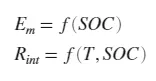
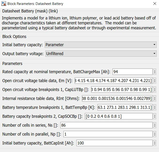
The Datasheet Battery block implements a lithium-ion, lithium-polymer, or lead-acid battery that you can parameterize using manufacturer data. To create the open-circuit voltage and internal resistance parameters that you need for the block, use the manufacturer discharge characteristics by temperature data the battery output voltage, the block uses lookup tables for the battery open-circuit voltage and the internal resistance. The lookup tables are functions of the state-of charge (SOC) and battery temperature, characterizing the battery performance at various operating points:
To calculate the voltage, the block implements these equations.
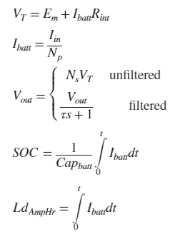
Positive current indicates battery discharge. Negative current indicates battery charge.
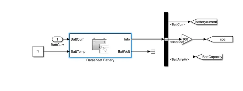
Complete model of the Lithium ion battery by Implement a model for a lithium ion model by the Datasheet.
Temperature Sensor block:
The Temperature Sensor block represents an ideal temperature sensor, that is, a device that determines the temperature differential measured between two points without drawing any heat.
Connections A and B are thermal conserving ports that connect to the two points where temperature is being monitored. Port T is a physical signal port that outputs the temperature differential value.
The block positive direction is from port A to port B. The measured temperature is determined as T = TA – TB.
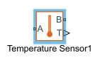
The block has the following ports:
- A -Thermal conserving port associated with the sensor positive probe.
B -Thermal conserving port associated with the sensor negative probe.T -Physical signal output port for temperature
Reference Velocity(Drive Cycle):
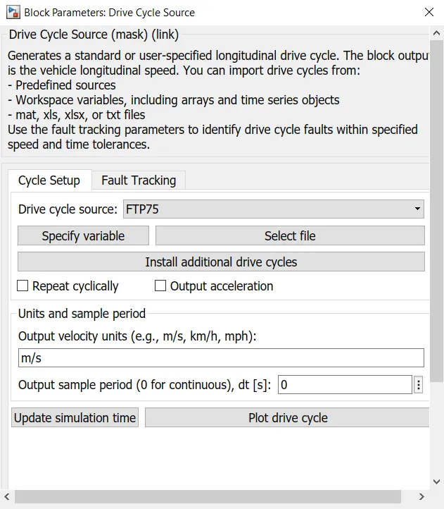
- The Drive cycle source block is used to provide the reference speed for the simulation.
- It generates is a standard or user-specified longitudinal drive cycle.
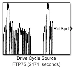
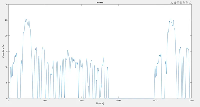
Here, the selected drive cycle is the standard FTP75.
The plot of the drive cycle is shown below
Signal Builder:
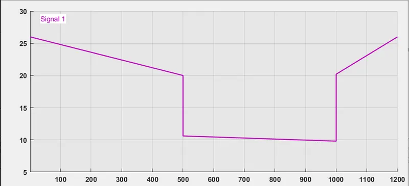
- The Signal Builder block allows you to create interchangeable groups of piecewise linear signal sources and use them in a model. You can quickly switch the signal groups into and out of a model to facilitate testing. In the Signal Builder window, create signals and define the output waveforms.
- Signal generate waveform for road inclination angle (Beta) and wind and we send the information to the Vehicle Body.
Multiport Switch:
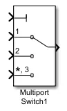
Multiport Switch block determines which of several inputs to the block passes to the output. The block bases this decision on the value of the first input. The first input is the control input and the remaining inputs are the data inputs. The value of the control input determines which data input passes to the output.
Complete Reference Model:
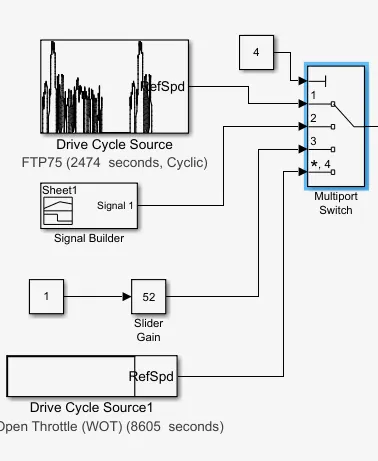
Simulink Model:
- In this model we use three different drive cycle like WTO, FTP75 and also through Signal Builder.
- The Controller will follow the given drive cycle reference and run the motor is the required rpm.
- The Current flows to DC Motor from the battery through the DC-DC Power Converter to the drive the motor.The required Voltage will be controlled in the Controller.
- Then the motor power is transmitted to the wheels of a vehicle through the gearbox, the controller will take the vehicle speed and the speed of the vehicle is as given in the drive cycle.
System Level Configuration:
MATLAB Model of Electric Car which uses Li-ion Battery and a Suitable Motor
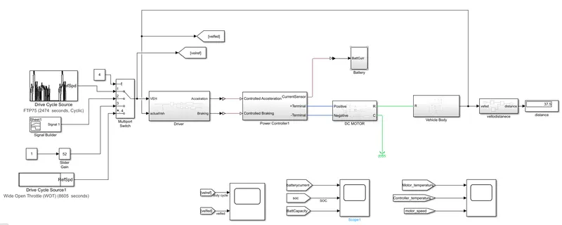
- The electric Vehicle model is represented by using MATLAB/Simulink.This model is a complete representation of an electric vehicle that is built using Powertrain Blockset.
- This model has vehicle dynamics and electrical system, the vehicle dynamics subsystem relates to the vehicle body and tires whereas the electrical system contains a subsystem related to the motor and battery pack. This subsystem contains various other componente which we will understand further.
Case:
1)Run the model on FTP75 drive cycle and get the result.
2)Run the model on WOT and get the result.
Result:
- The run time is kept at 2474 seconds because the total run time of the FTP drive cycle is 2474seconds.
- Now we will see the actual drive cycle and the reference cycle.
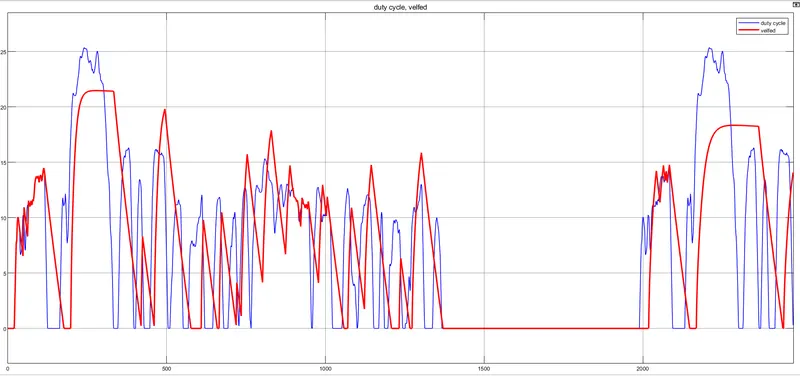
- From the plot it is evident that the actual drive cycle is almost matching with the reference drive cycle.
- But the peak velocity is lesser in the actual drive cycle(22m/s). This is because of many factors, The rolling resistance of the vehicle is taken into the consideration and hence this will affect the velocity of the vehicle.
- The wind velocity also affect the speed of the Vehicle.
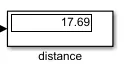
From this drive cycle the Vehicle can able to cover the distance of 17.69
Battery Current ,SOC and the Battery Capacity:
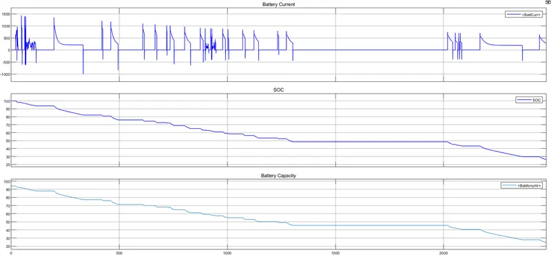
- The State of Charge in the FTP75 drive cycle is from 100 to 22 and the Battery Capacity is 94Ah and it reduced due to the drive cycle and it reaches 25Ah in 2474sec of the drive cycle and this is due to the when the vehicle is before start the Battery Capacity is high when it drive the charges present in the battery is keep on reducing so that battery capacity is keep on reducing when it reduced Completly the Battery need to be charge.
Motor Temperature, Controller Temperature and the Motor Speed:
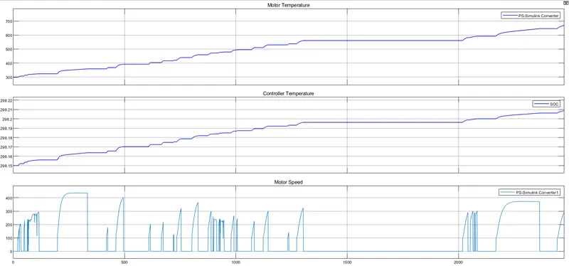
- The motor perform based on the drive cycle when the drive cycle reference velocity increased motor speed keep on increasing when it reduce the motor speed keep on reduced but it does not match exactly with drive cycle because the motor operation when the drive cycle is reduced fastely the motor cannot able to reduce that much fast because the braking operation performed here from 100-0 it takes atleast 10sec so that we cannot match exactly with the drive cycle.
- The motor temperature is increased from 300 to 700 within 2474 we need to provide coolant in this system so that motor perform better and controller temperature is maintained some what constant in this system.
WOT:
The Drive Cycle Source block generates a standard or user-specified longitudinal drive cycle. The block output is the specified vehicle longitudinal speed, which you can use to:
-
Predict the engine torque and fuel consumption that a vehicle requires to achieve desired speed and acceleration for a given gear shift reference.
-
Produce realistic velocity and shift references for closed loop acceleration and braking commands for vehicle control and plant models.
-
Study, tune, and optimize vehicle control, system performance, and system robustness over multiple drive cycles.
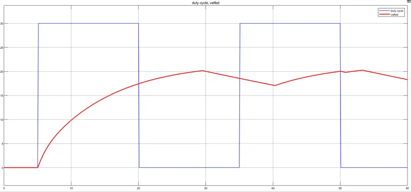
The above WOT drive cycle source block with the reference WOT with Velocity of the Vehicle.
Battery Current ,SOC and the Battery Capacity:
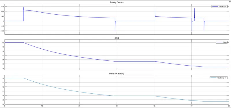
- The State of Charge in the WOT drive cycle is from 100 to 94 and the Battery Capacity is 94Ah and it reduced due to the drive cycle and it reaches 88.5Ah in 90sec of the drive cycle and this is due to the when the vehicle is before start the Battery Capacity is high when it drive the charges present in the battery is keep on reducing so that battery capacity is keep on reducing when it reduced Completly the Battery need to be charge.
Motor Temperature, Controller Temperature and the Motor Speed:
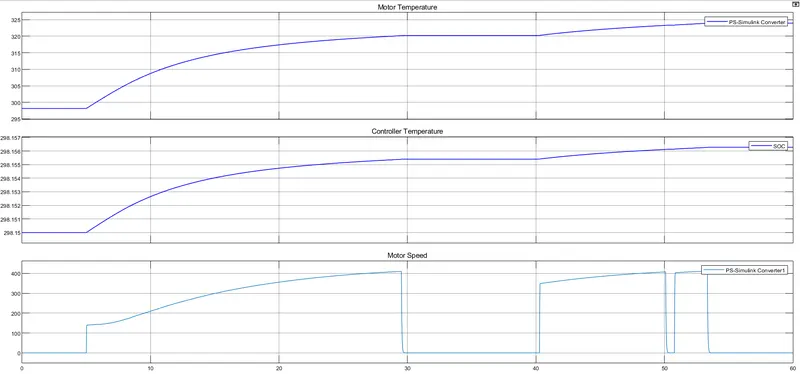
- The motor perform based on the drive cycle when the drive cycle reference velocity increased motor speed keep on increasing when it reduce the motor speed keep on reduced but it does not match exactly with drive cycle because the motor operation when the drive cycle is reduced fastely the motor cannot able to reduce that much fast because the braking operation performed here from 100-0 it takes atleast 10sec so that we cannot match exactly with the drive cycle.
- The motor temperature is increased from 298 to 305 within 90 we need to provide coolant in this system so that motor perform better and controller temperature is maintained some what constant in this system.
Conclusion:
We Create a MATLAB model of an electric car which uses lithium ion battery with suitable motor and by using suitable blocks from the Simscape or Powertrain Block set , We Implement the vehicle speed control using PI Controller and generate a brake and accelerator commands, we have seen the System level Configuration, Model Parameters and the model run as per our reference input give with less error in it due to PID Controller.