Project 1 (Mini Project on Vehicle Direction Detection
AIM OF THE PROJECT:
To Identify the direction of the vehicle in Autotonomous driving and Advanced Driver Assistance Features.
STEP-1: REQUIREMENT ANALYSIS
In this project we have two requirements.
Requirement - 1:
- Steering wheel input as yaw rate (Signal name: SteeringWheel_YawDegreeInput) is the input for this system.
- This is compared against 3 angular values, one each for left turn, right turn & straight drive (Calibration Values: Right_Turn_AngularLimit, Left_Turn_AngularLimit,
- Straight_Drive_Steering_Angle) to say which specific direction the steering wheel is turning
- towards.
- Use switch blocks to compare & develop this requirement. Keep this requirement in a subsystem & output of this requirement is a local signal (Signal Name: Vehicle_Turn_Status).
Requirement – 2:
- Keep this requirement as a separate subsystem. Inputs to this requirement are local signal from requirement 1 (Signal Name: Vehicle_Turn_Status) & an input signal from camera (Signal Name: CameraInput_RoadSign), which confirms the occurrence of a road sign.
- Signal Vehicle_Turn_Status is compared against calibration values (Calibration Values: RightTurn_RoadSign, LeftTurn_RoadSign, Straight_RoadSign), if each of them is found equal, then each of the three corresponding output is compared against the camera input signal,
- Using a logical operator block, only one among them is finally given as output signal (Signal Name: Vehicle_Direction_Indicator).
-
Signal / Calibration Name
Signal Type
Data Type
Dimension
Min
Max
Initial Value
Units
-
SteeringWheel_YawDegreeInput
Input
Int16
1
-180
180
-
Deg
CameraInput_RoadSign
Input
Boolean
1
0
1
-
-
Vehicle_Turn_Status
Local
Int16
1
-180
180
-
Deg
Right_Turn_AngularLimit
Calibration
Int16
[11]
-180
180
30
Deg
Left_Turn_AngularLimit
Calibration
Int16
[1 1]
-180
180
-120
Deg
Straight_Drive_Steering_Angle
Calibration
Int16
[1 1]
-180
180
0
Deg
RightTurn_RoadSign
Calibration
Int16
[1 1]
-180
180
30
LeftTurn_RoadSign
Calibration
Int16
[1 1]
-180
180
-120
Straight_RoadSign
Calibration
Int16
[1 1]
-180
180
0
Vehicle_Direction_Indicator
Output
Boolean
1
0
1
-
-
STEP-2: MODEL DEVELOPMENT
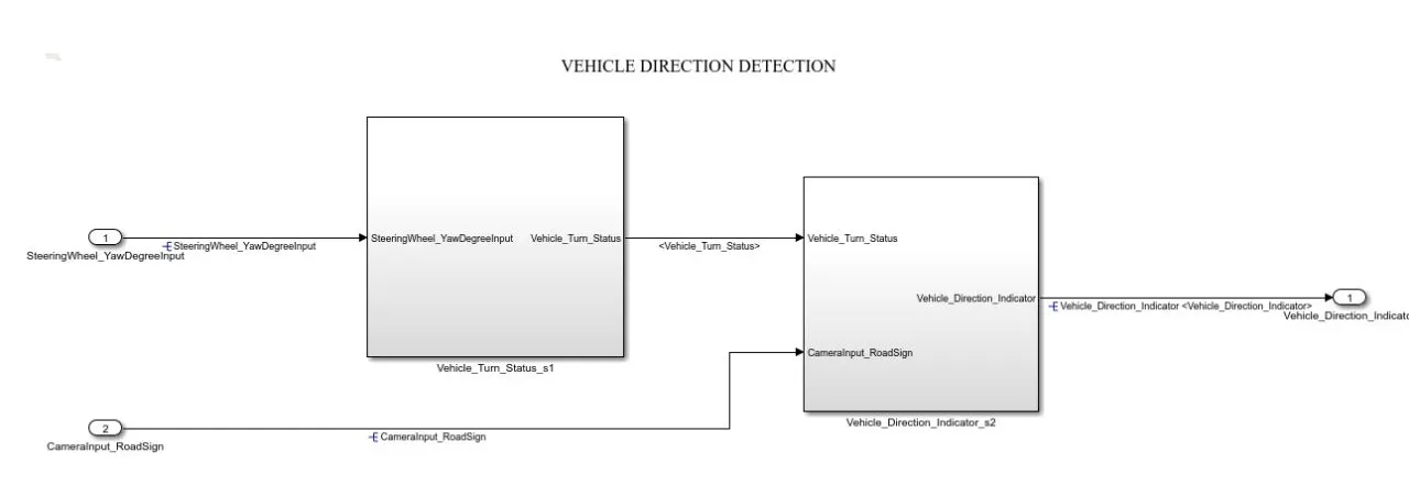
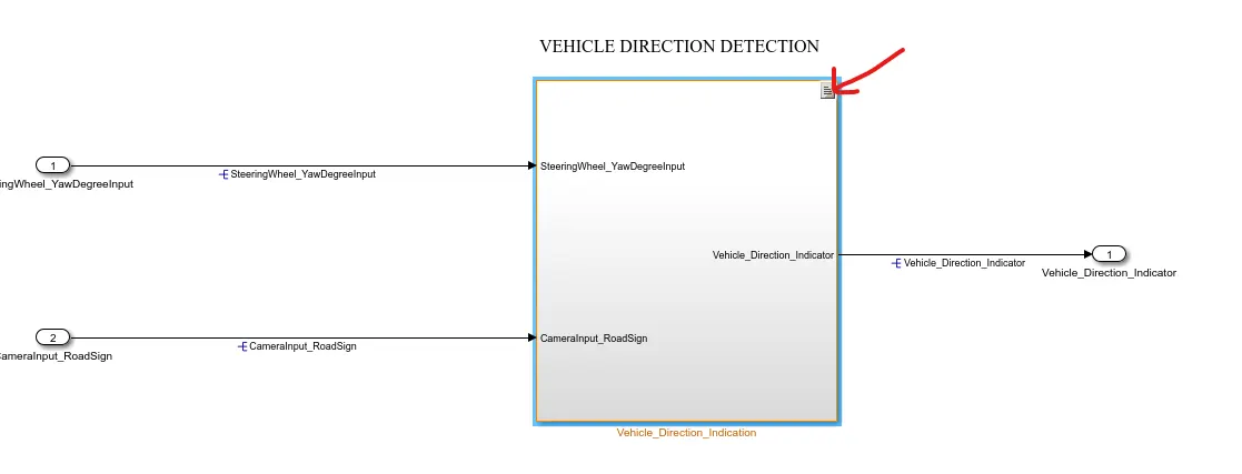
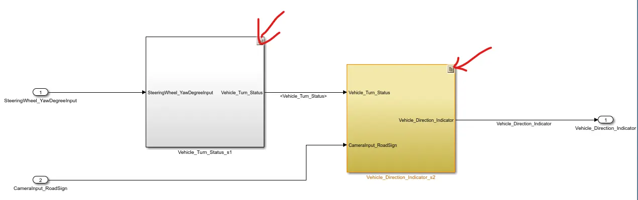
This the main model subsystem that having two inputs SteeringWheel_YawDegreeInput and CameraInput_RoadSign entering into the Vehicle Detection Determination subsystem and one output Vehicle_Direction_Indicator
there are 2 requirements are designed in two subsystem
Requirement - 1:
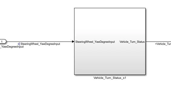
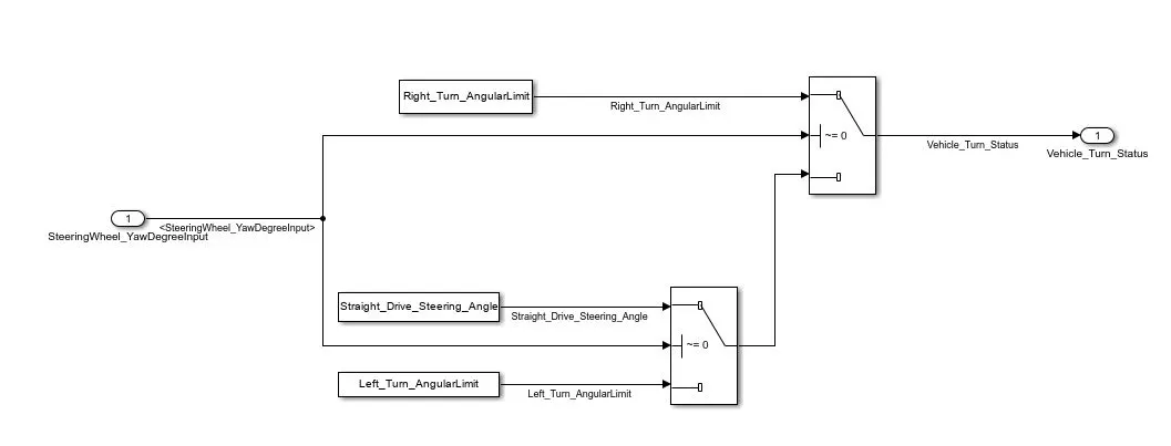
- Steering wheel input as yaw rate (Signal name: SteeringWheel_YawDegreeInput) is the input for this system.
- This is compared against 3 angular values, one each for left turn, right turn & straight drive (Calibration Values: Right_Turn_AngularLimit, Left_Turn_AngularLimit, Straight_Drive_Steering_Angle) to say which specific direction the steering wheel is turning towards.
- Use switch blocks to compare & develop this requirement. Keep this requirement in a subsystem & output of this requirement is a local signal (Signal Name: Vehicle_Turn_Status).
- The model looks like below,
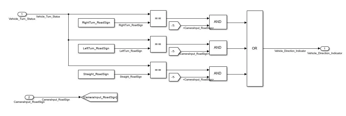
Requirement – 2:
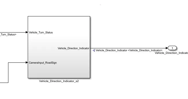
- Keep this requirement as a separate subsystem. Inputs to this requirement are local signal from requirement 1 (Signal Name: Vehicle_Turn_Status) & an input signal from camera (Signal Name: CameraInput_RoadSign), which confirms the occurrence of a road sign.
- Signal Vehicle_Turn_Status is compared against calibration values (Calibration Values: RightTurn_RoadSign, LeftTurn_RoadSign, Straight_RoadSign), if each of them is found equal, then each of the three corresponding output is compared against the camera input signal,
- Using a logical operator block, only one among them is finally given as output signal (Signal Name: Vehicle_Direction_Indicator).
- The model looks like below,
STEP-3: SLDD-SIMULINK DATA DICTIONARY
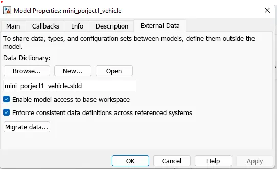
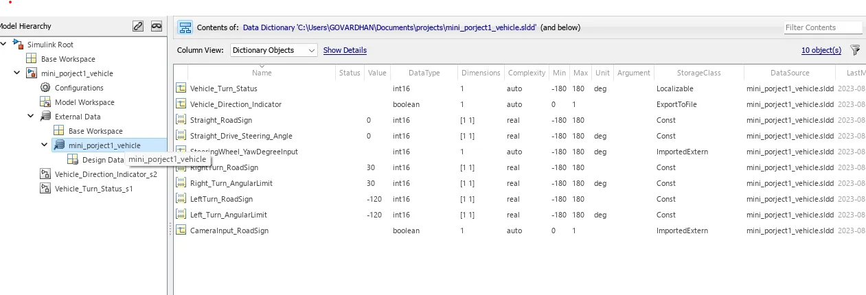
all the inputs, outputs, calibration parameters are saved in SLDD so while simulation the model takes all the values and its parameters from the Simulink Data Dictionary.
->After creating of SLDD file link the SLDD file with model.
STEP-4: SIGNAL RESOLVING & RESOLUTION
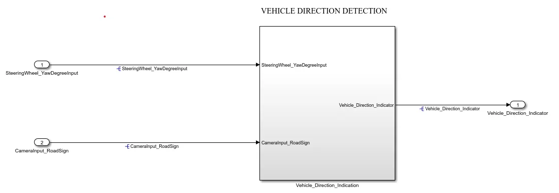
the inputs and output signals are resolved so the signals will take the values from sldd and pass them to the logical blocks. Otherwise, it may take some junk values if it is unresolved.
STEP-5: MODEL UPDATE
The model update is done by Ctrl-D. this is done to check for any static errors. If there are no errors coming the model is working fine without any errors.
STEP-6: CONFIGURATION PARAMETERS UPDATE
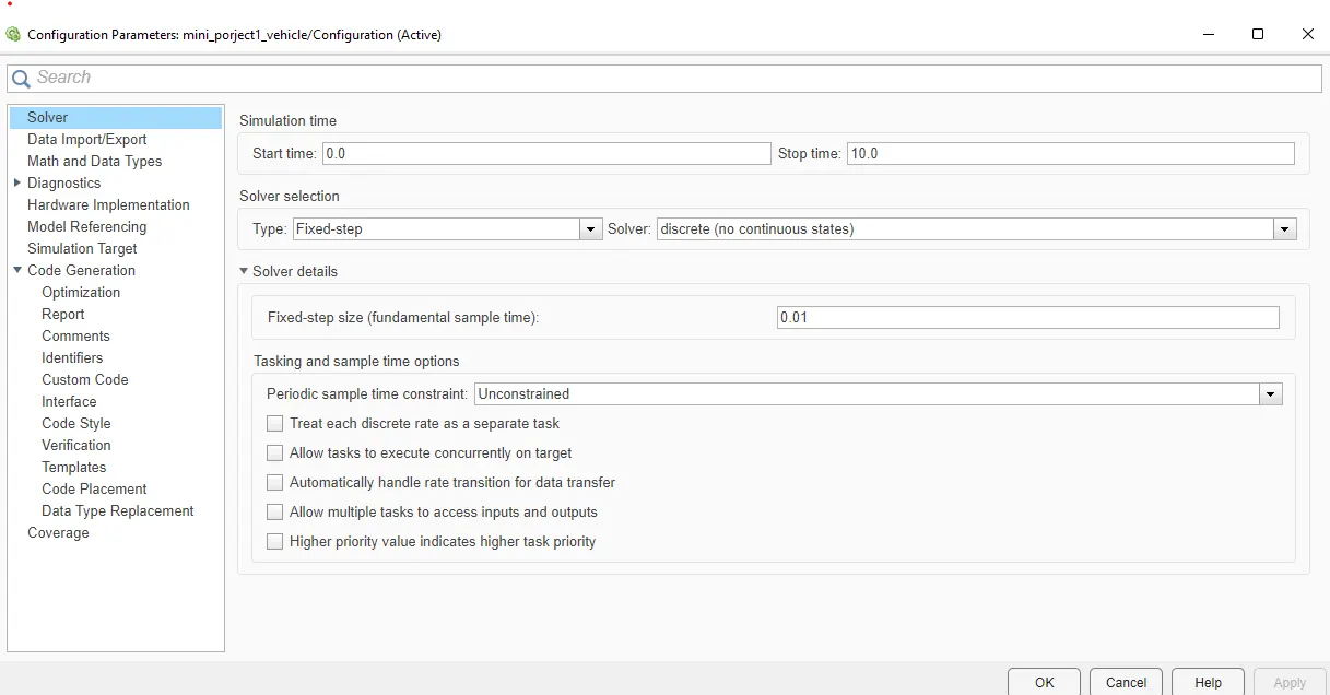
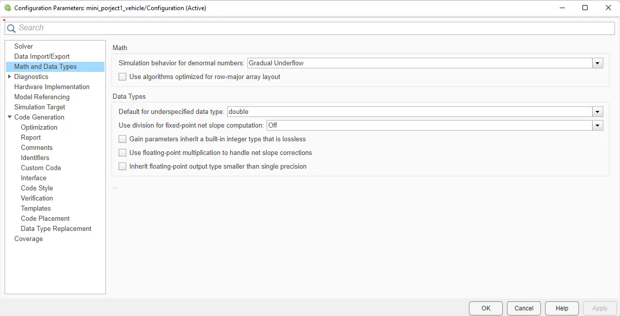
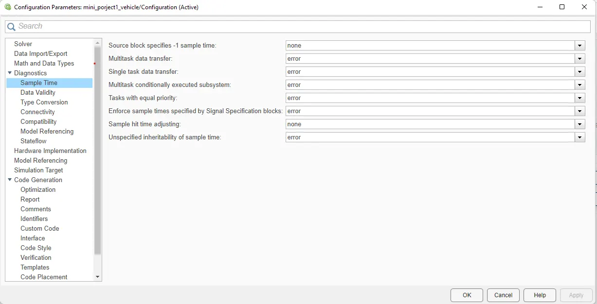
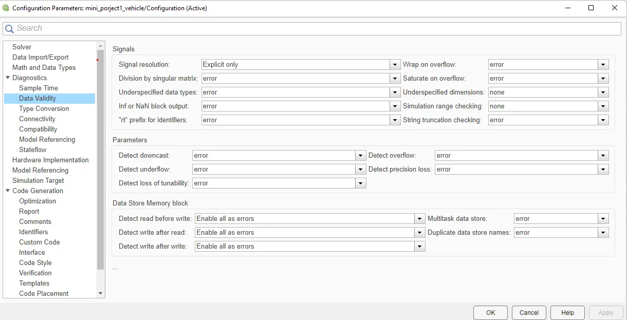
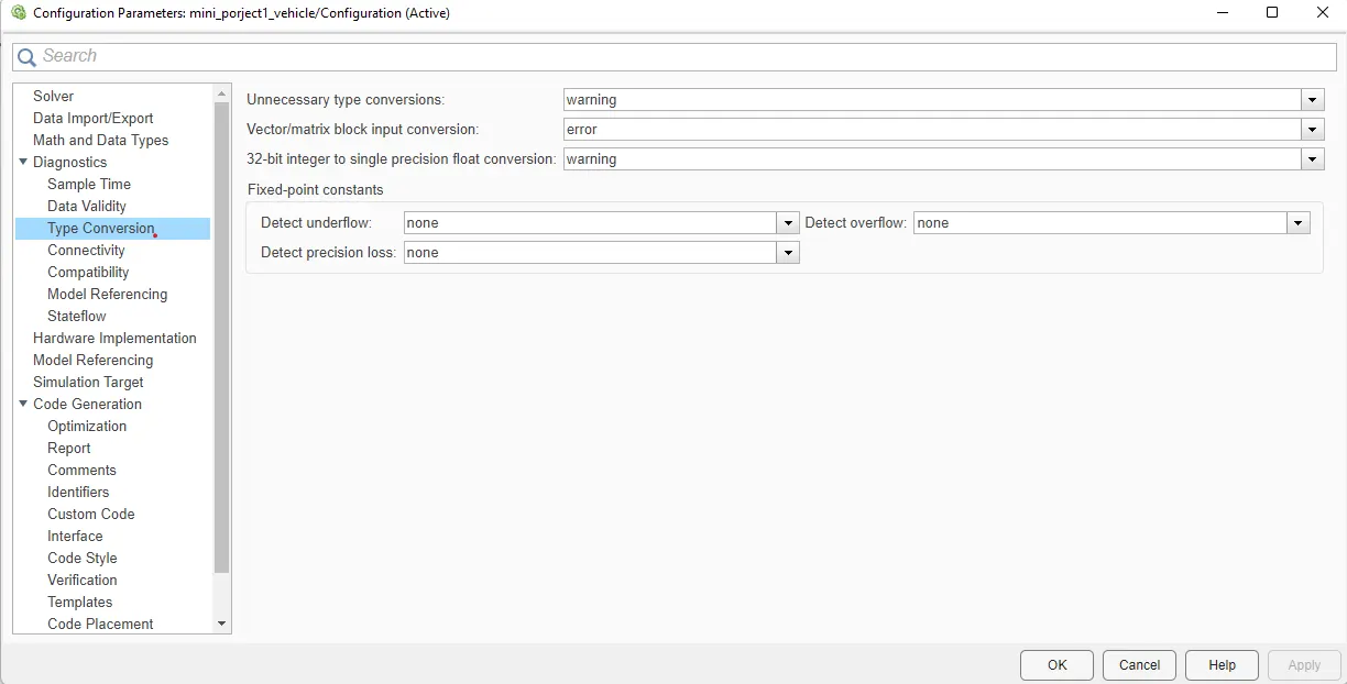
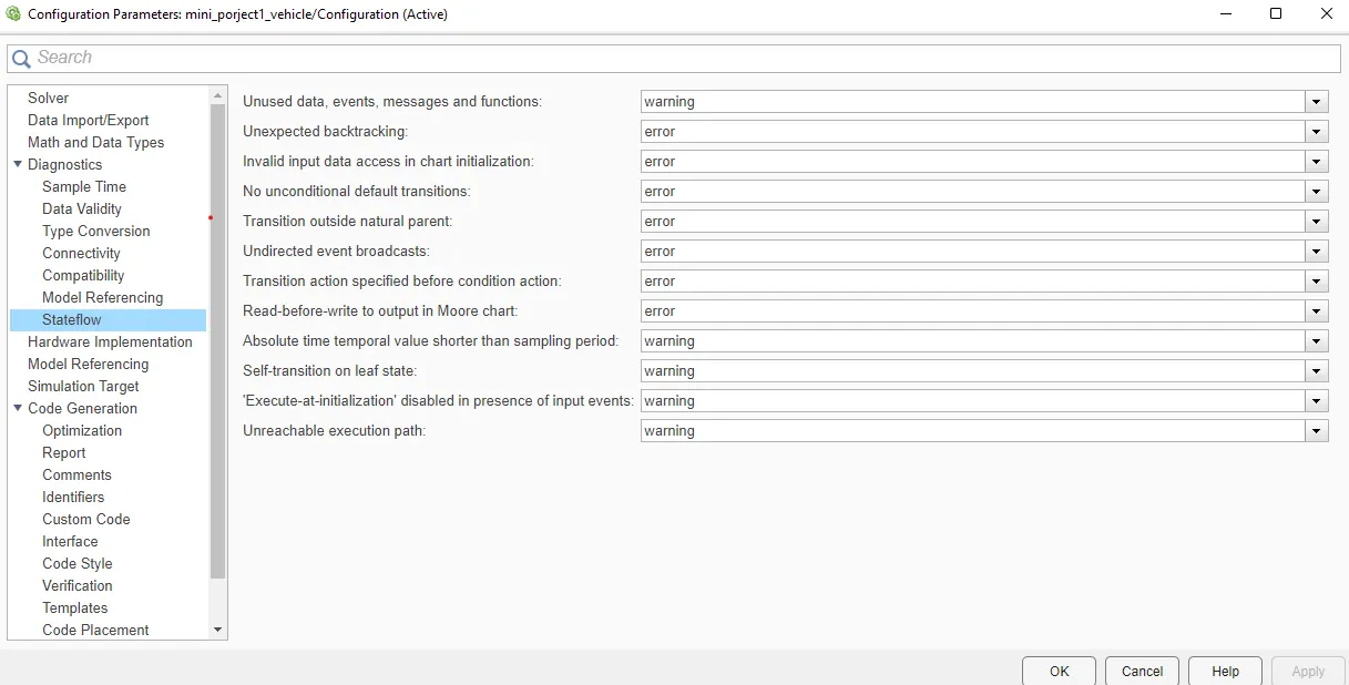
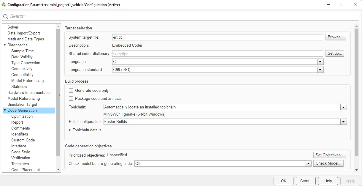
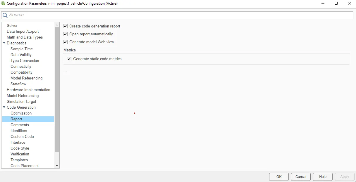
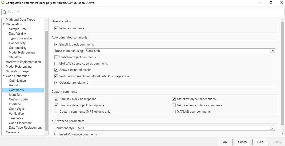
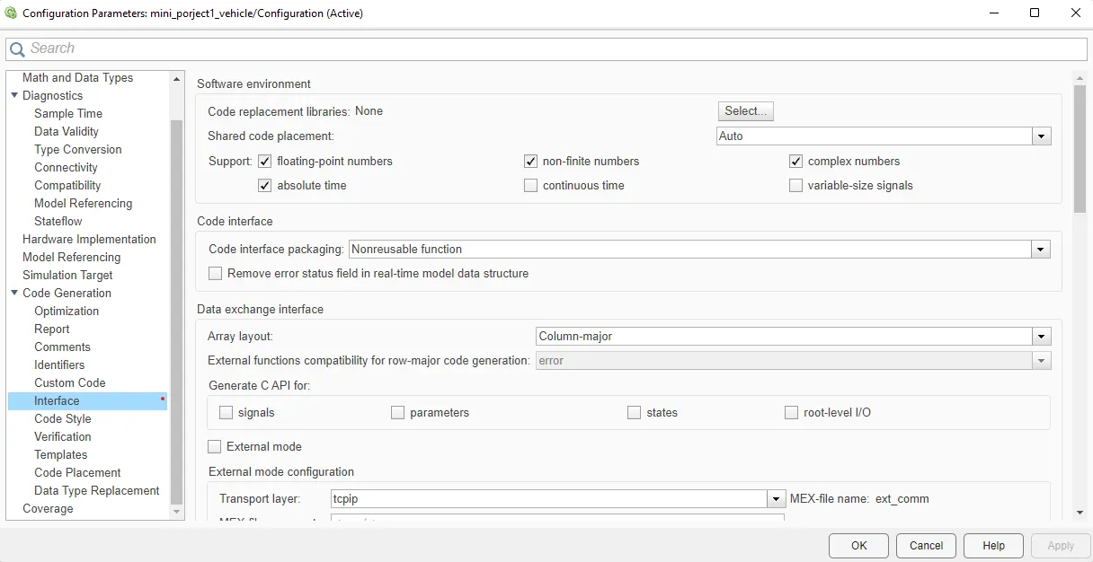
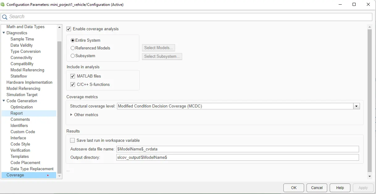
Various configuration parameters are updated as per the code generation the solver type should be fix for code generation.
STEP-7: REQUIREMENT TAGGING
All the requirements are tagged in order for better understandability, anyone who is reviewing the model or who is trying to update the model can get a clear idea of what logic is used in the system. from the requirement manager, we can see what are all are tagged and the description.
STEP-8: MODEL ADVISOR CHECKS
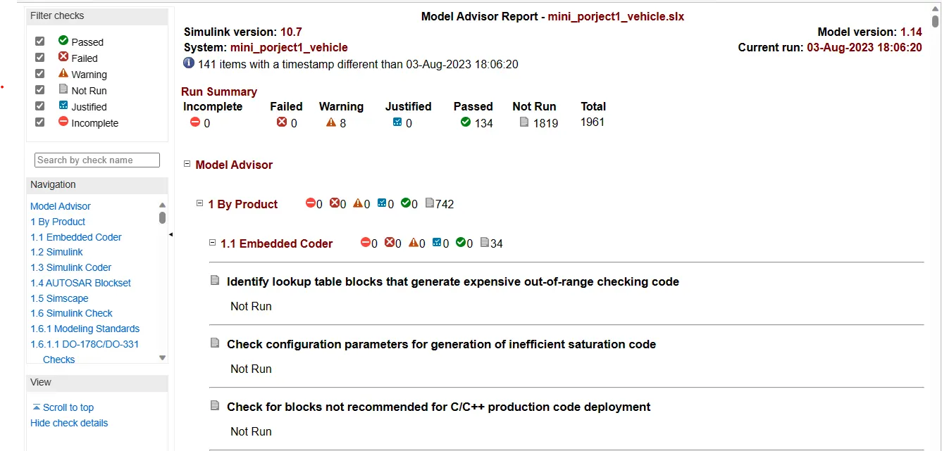
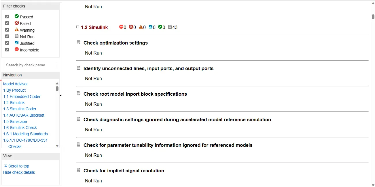
By running the model advisor tool, we can see commonly made modelling errors.
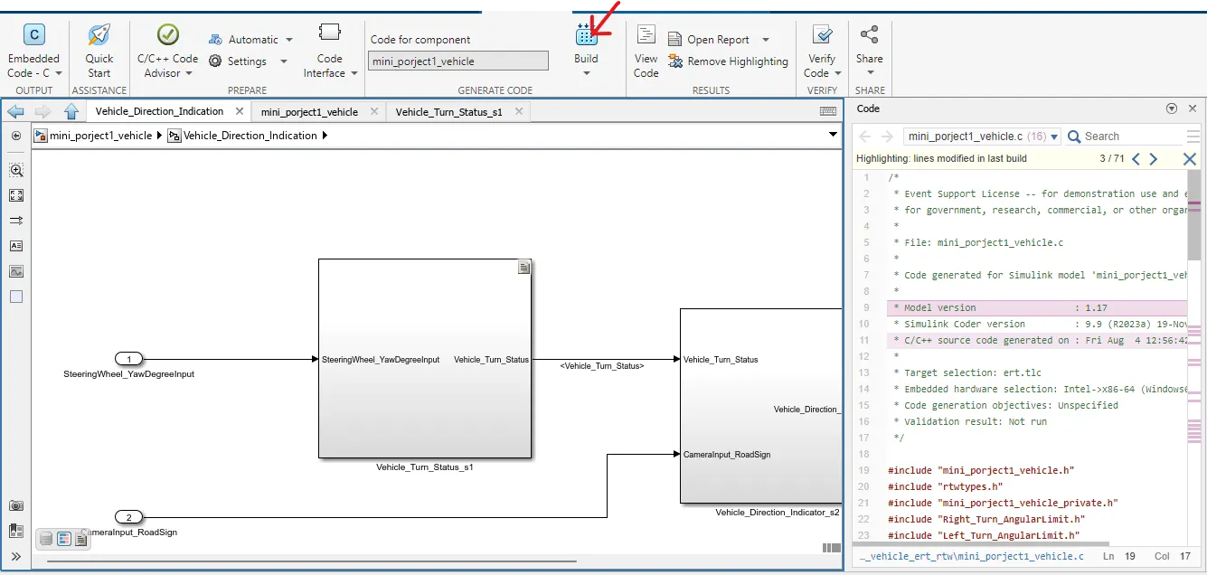
STEP-9: CODE GENERATION
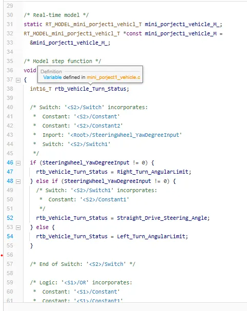
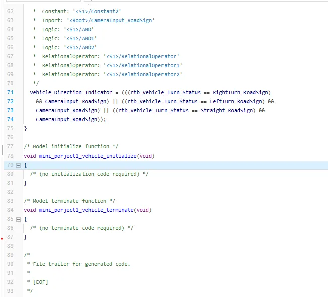
build model for generating code.
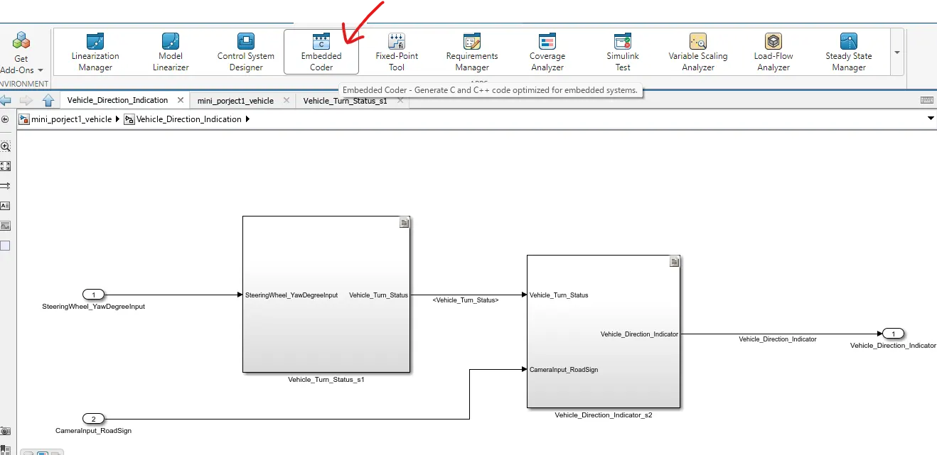
Click on Buiid to generate code.
RESULT:
The vehicle direction determination is modelled as per the requirement, all the signals are defined in Simulink data dictionary. All input and output signals are resolved and propagated. Updated the model to check for static errors. Run the model advisor tool to see any errors. since there are no errors in Model Advisor Report. Code has been generated using Embedded Coder.