Project 1 (Mini Project on Vehicle Direction Detection
WEEK_11_Challenge: MINI Project:
Mini Project - Vehicle Direction Determination
Abstract:
Identifying the direction of the vehicle is one of the important & diverse features in Autonomous driving & Advanced Driver Assistance Features. This particular sub-feature of identifying the direction of vehicle is basically identifying the direction the vehicle is taking based on the camera input.
Camera reads the road signs & stores into its memory with unique values for left turn, right turn & straight drive. Depending on the direction it is taking, final indication is given to the driver – as an indication if he is driving in the recommended direction or not.
Vehicle Direction Determination can also be coupled along - side features like GPS systems to identify whether the vehicle is reaching its destination in an optimized manner. This sub feature can also be used along with Lane Detection, Highway Warning, Ramp Entry / Exit in Wrong Way Detection etc.
Objective:
- Development of MATLAB Simulink model as per requirement.
- Tag the requirements to the simulink model; tagging requirement 1 & requirement 2 to their corresponding subsystems is fine.
- MBD compliant changes, Data Dictionary creation & code generation is added advantage, and that is not scope of this project.
- If choosing code generation, Storage class for Input signals: ImportedExtern; Storage class for Output signal: Export to File; Storage class for local signals: localizable; Storage class for calibration signals: Const.
- Choose sample time for all signals as 0.01s.
Requirement - 1:
- Steering wheel input as yaw rate (Signal name: SteeringWheel_YawDegreeInput) is the input for this system.
- This is compared against 3 angular values, one each for left turn, right turn & straight drive (Calibration Values: Right_Turn_AngularLimit, Left_Turn_AngularLimit, Straight_Drive_Steering_Angle) to say which specific direction the steering wheel is turning towards.
- Use switch blocks to compare & develop this requirement. Keep this requirement in a subsystem & output of this requirement is a local signal (Signal Name: Vehicle_Turn_Status).
Requirement – 2:
- Keep this requirement as a separate subsystem. Inputs to this requirement are local signal from requirement 1 (Signal Name: Vehicle_Turn_Status) & an input signal from camera (Signal Name: CameraInput_RoadSign), which confirms the occurrence of a road sign.
- Signal Vehicle_Turn_Status is compared against calibration values (Calibration Values: RightTurn_RoadSign, LeftTurn_RoadSign, Straight_RoadSign), if each of them is found equal, then each of the three corresponding output is compared against the camera input signal,
- Using a logical operator block, only one among them is finally given as output signal (Signal Name: Vehicle_Direction_Indicator).
Given SLDD Data:
Signals & Calibration Data List:
|
Signal / Calibration Name |
Signal Type |
Data Type |
Dimension |
Min |
Max |
Initial Value |
Units |
|
SteeringWheel_YawDegreeInput |
Input |
Int16 |
1 |
-180 |
180 |
- |
Deg |
|
CameraInput_RoadSign |
Input |
Boolean |
1 |
0 |
1 |
- |
- |
|
Vehicle_Turn_Status |
Local |
Int16 |
1 |
-180 |
180 |
- |
Deg |
|
Right_Turn_AngularLimit |
Calibration |
Int16 |
[1 1] |
-180 |
180 |
30 |
Deg |
|
Left_Turn_AngularLimit |
Calibration |
Int16 |
[1 1] |
-180 |
180 |
-120 |
Deg |
|
Straight_Drive_Steering_Angle |
Calibration |
Int16 |
[1 1] |
-180 |
180 |
0 |
Deg |
|
RightTurn_RoadSign |
Calibration |
Int16 |
[1 1] |
-180 |
180 |
30 |
|
|
LeftTurn_RoadSign |
Calibration |
Int16 |
[1 1] |
-180 |
180 |
-120 |
|
|
Straight_RoadSign |
Calibration |
Int16 |
[1 1] |
-180 |
180 |
0 |
|
|
Vehicle_Direction_Indicator |
Output |
Boolean |
1 |
0 |
1 |
- |
- |
SOFTWARE VERSION USED:
MATLAB R2018a.
Procedure to design Simulink Model
- 1) Open the MATLAB à Open Simulink Blank Model à Open Simulink Library à From Library take required blocks as per requirement 1 and 2.
Requirement 1:
- Open Simulink Blank Model à Add Inport, Outport, Constant Block (Rename them as Calibration values) and Switch block à Then Save this model as one Subsystem.
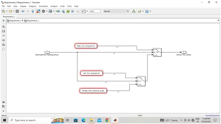
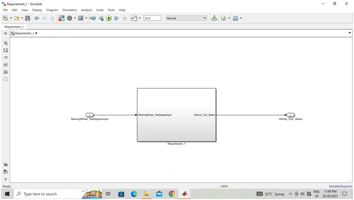
Requirement 2:
- Open Simulink Blank Model à Add Inport, Outport, Constant Block (Rename them as Calibration values) and AND Block (Logical Block) à Then Save this model as one Subsystem.
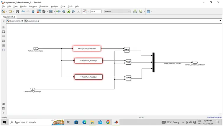
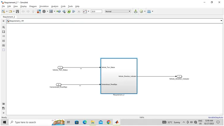
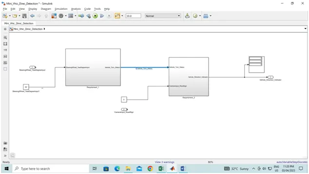
- Then Combine the both requirement 1 and requirement 2 block as one file.
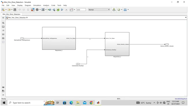
- Then Create the SLDD file as per the given Data.
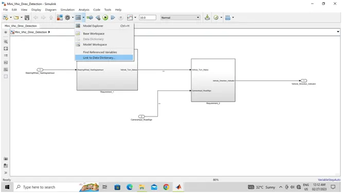
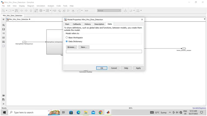
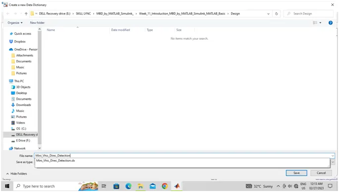
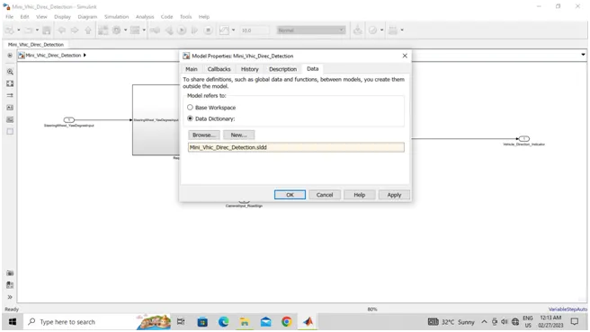
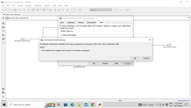
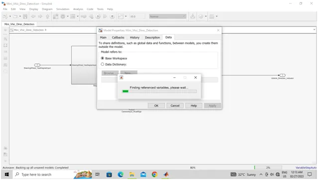
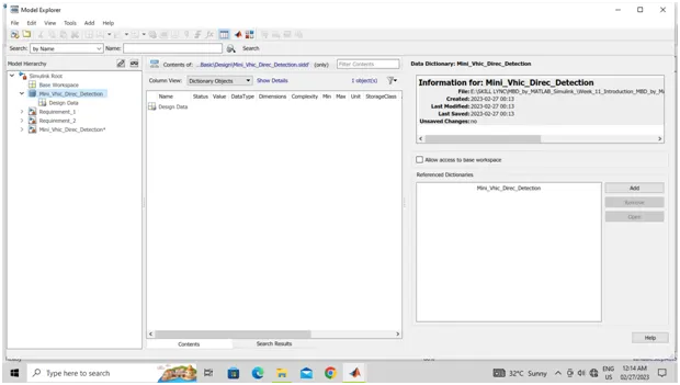
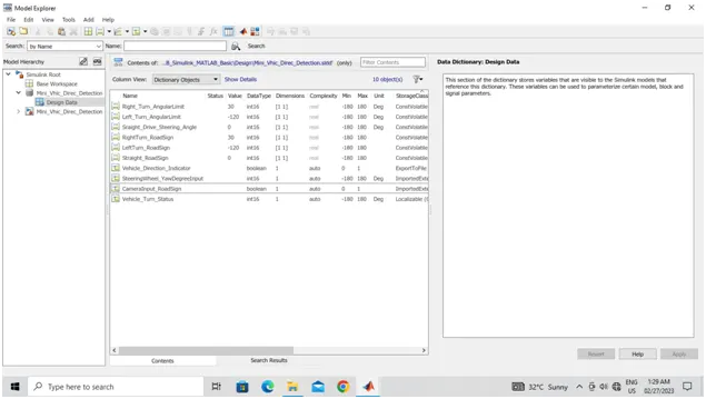
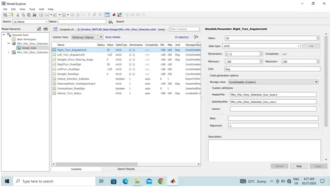
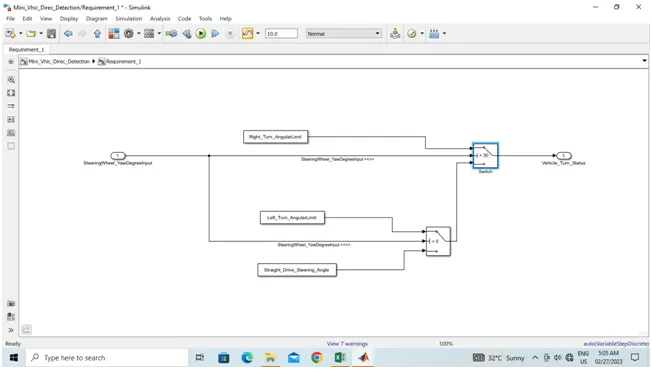
- As per the given data SLDD is created.
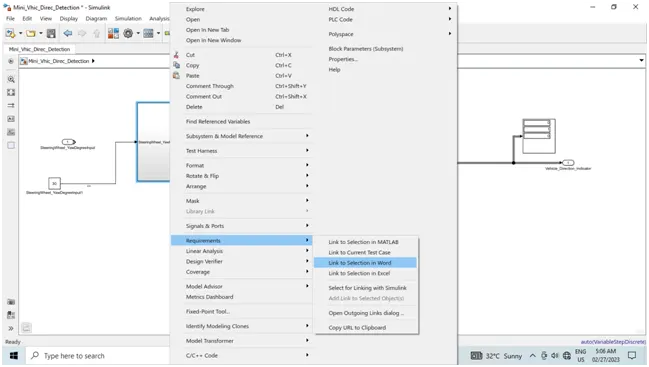
- Requirement is linked as per the given word file.
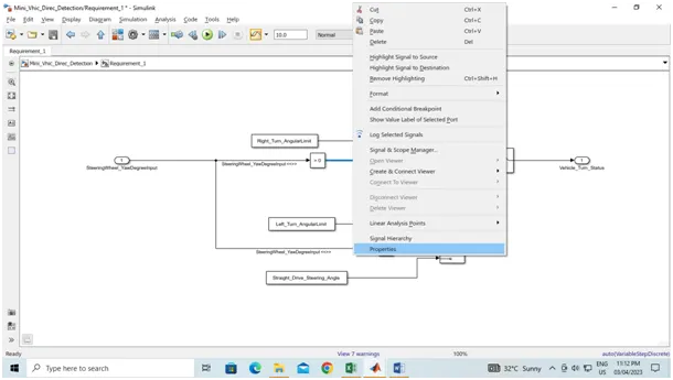
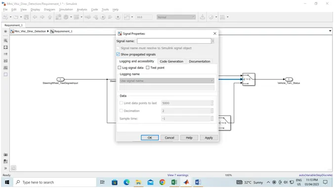
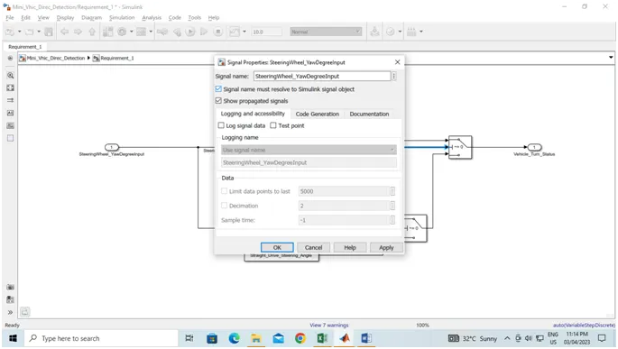
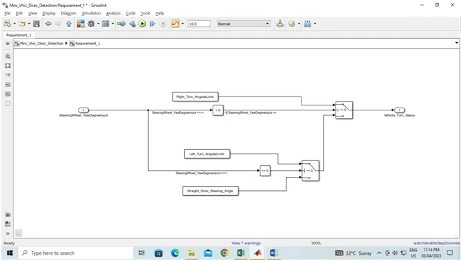
- By clicking on signal properties à Creating Signal Propagation and Signal name can resolved by the following screen shots.
Solver Settings:
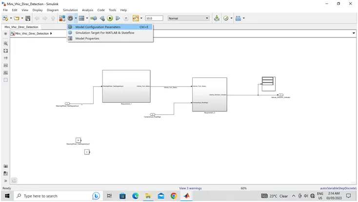
- Solver settings are important to simulate the model. To open the solver setings, go to the Modeling section which is at the top of simulink window. And select the Model settings under the modeling section.
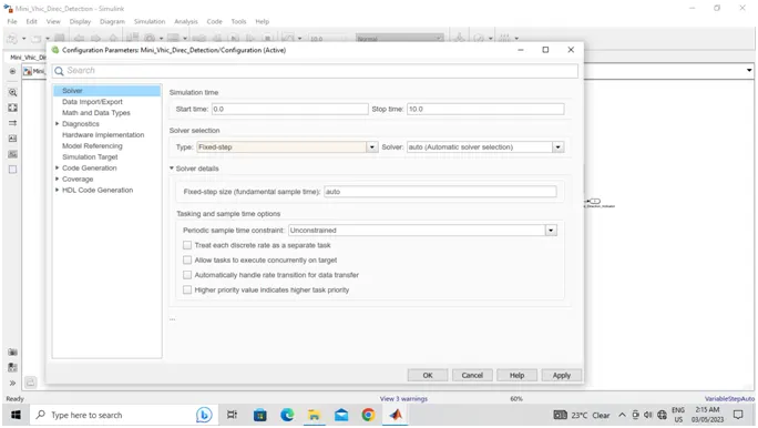
- In the configuration window, click on solver to model the solver parameters.
- Now change the type to Fixed-step, Solver to discrete(no continuous states) and take sample time as 0.01sec. Then click Ok.
- This settings are shown in the following figure.
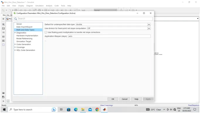
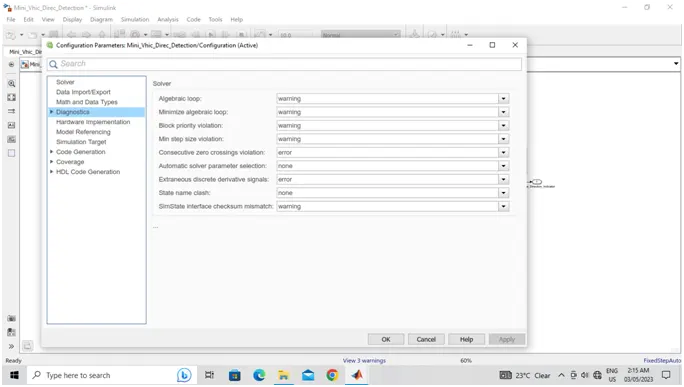
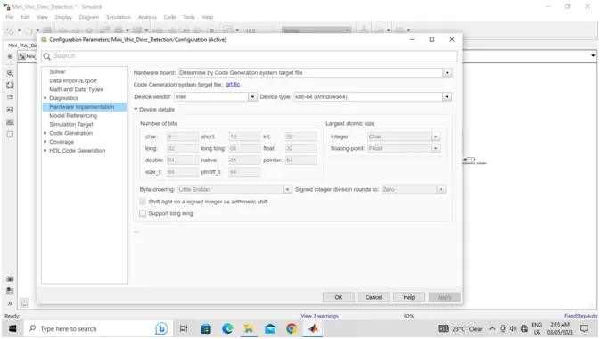
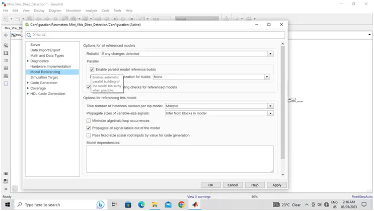
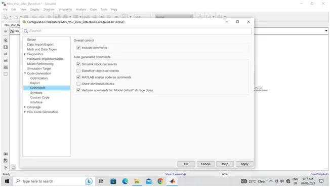
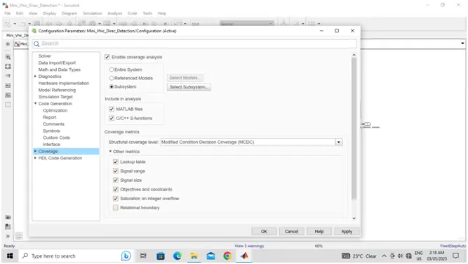
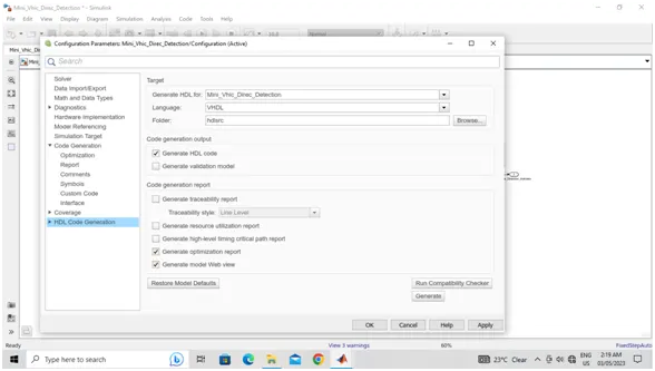
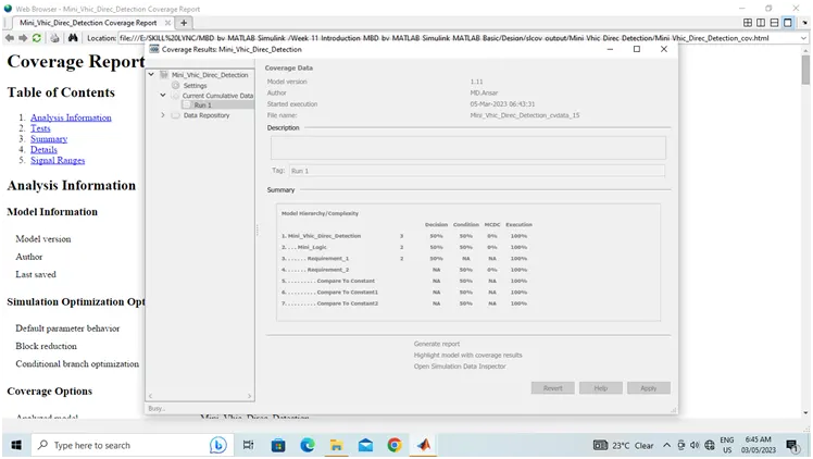
- Doing Coverage testing.
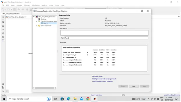
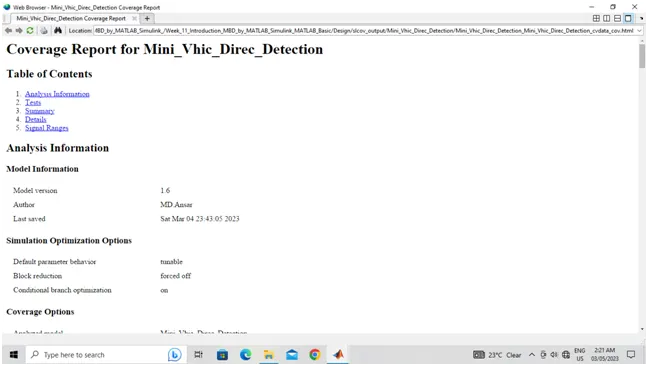
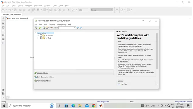
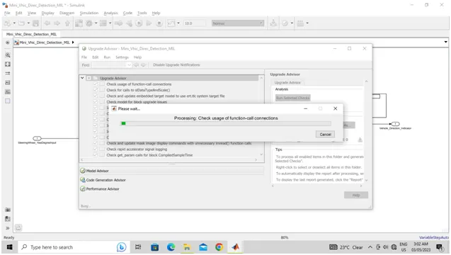
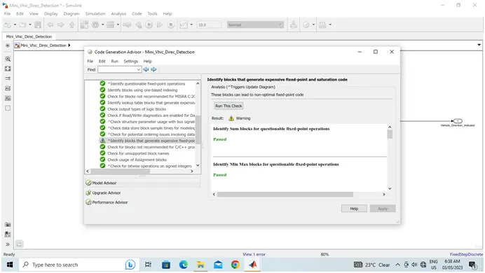
- Doing Model advisor for the model.
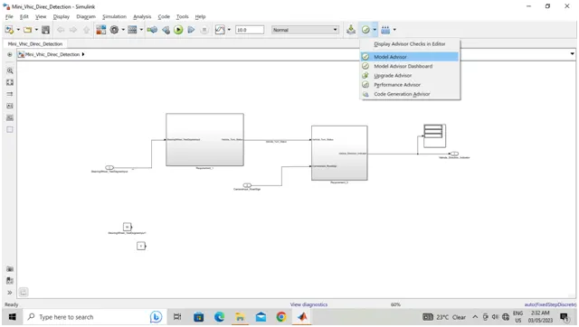
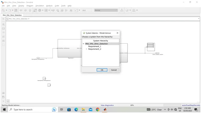

Procedure to create MIL test Environment:
- Open the MATLAB à Create the Test Cases.
- 2) By using the Test Cases are Signal builder is designed, the *.xlsx file is attached.
Simulation Time |
SteeringWheel_YawDegreeInput |
CameraInput_RoadSign |
Vehicle_Direction_Indicator |
Right |
Left |
Straight |
|
0 |
0 |
1 |
0 |
0 |
0 |
1 |
|
1 |
0 |
1 |
0 |
0 |
0 |
1 |
|
1 |
30 |
1 |
1 |
1 |
0 |
0 |
|
2 |
30 |
1 |
1 |
1 |
0 |
0 |
|
2 |
-120 |
1 |
0 |
0 |
1 |
0 |
|
3 |
-120 |
1 |
0 |
0 |
1 |
0 |
|
3 |
45 |
0 |
0 |
0 |
0 |
0 |
|
4 |
45 |
0 |
0 |
0 |
0 |
0 |
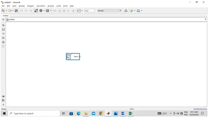
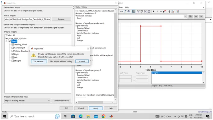
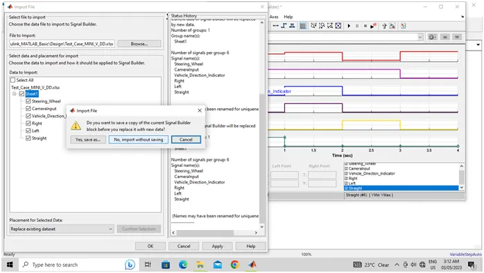
- Open Simulink File --> Add Signal Builder Block to the Simulink File --> Double Click on Signal Builder --> Select File --> Import from File --> Browse --> Select File that to import Data --> Click on Open , it will take a time to upload it --> Select the file and Place where the Data to upload --> Select ‘ Replace existing dataset --> Confirm Selection --> Click on Apply --> Select ‘No, import without saving / Yes, Save as..,’--> Then Click on OK.
- Then the file will be created and saved.
- Then connect to the given system.
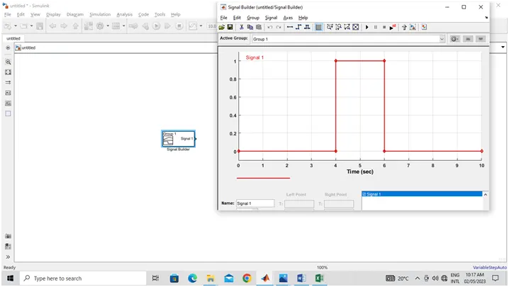
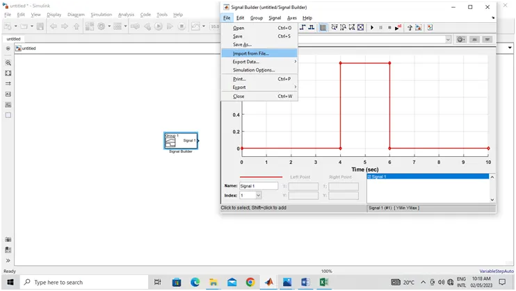
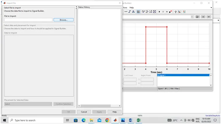
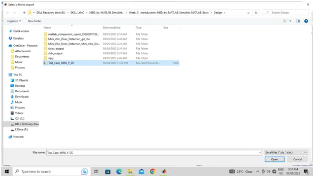
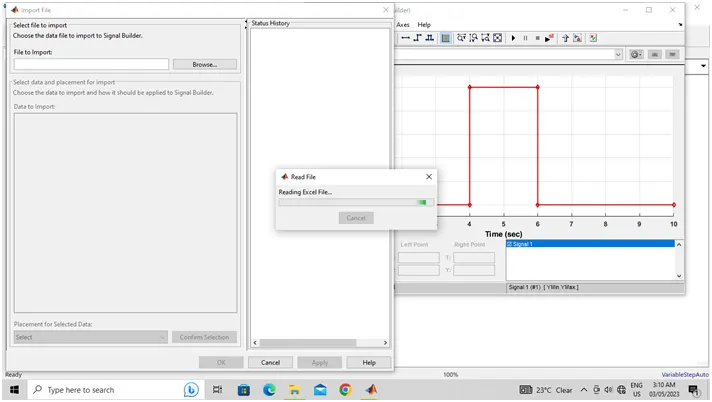
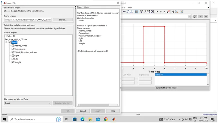
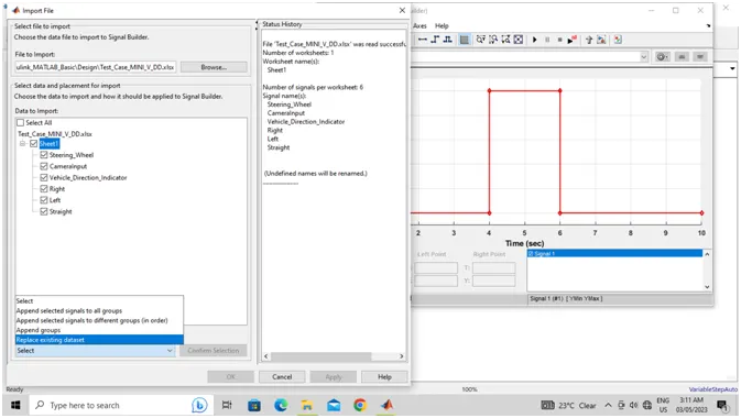
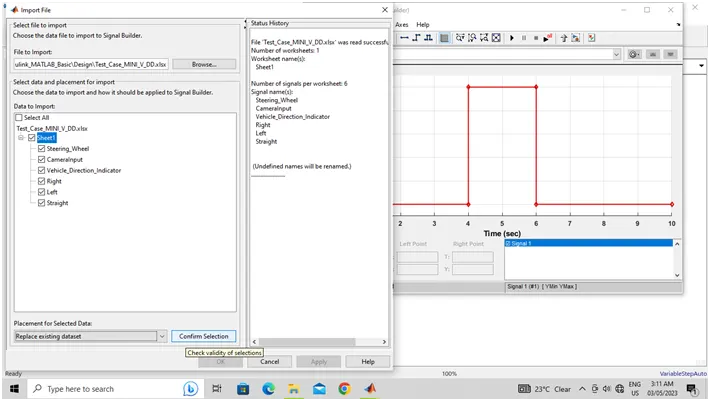
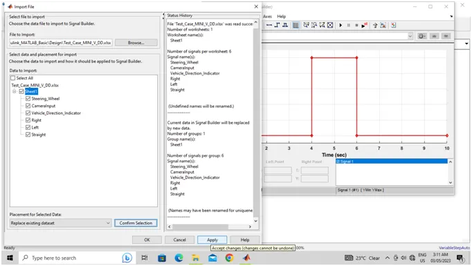
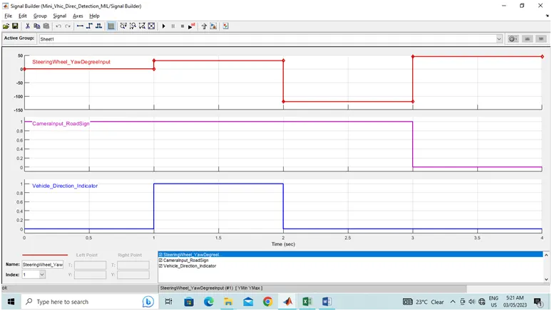
- As per the test cases is created into the logic environment and sum as sum/compare environment bock.
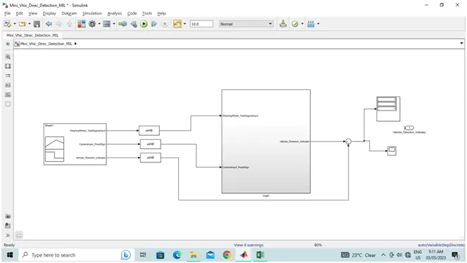
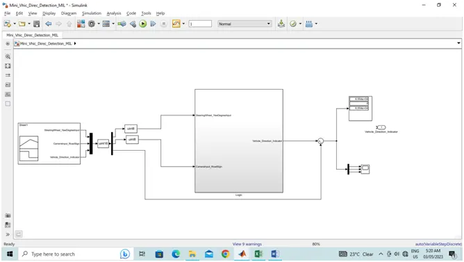
- 3) Open the given Simulink file “Mini_Vhic_Direc_Detection.slx” à Press Run à Open Model Explorer à Click on ‘Link to Data Dictionary’ à Select New à save the files and update the Data Dictionary which had created
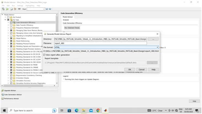
- It will take Time click on Show report à Click on Run Selected Task à Click on Generate Report à Click on the Report and Save it as a File. This report also sharing as a attachment.
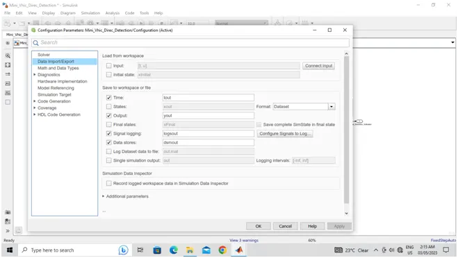
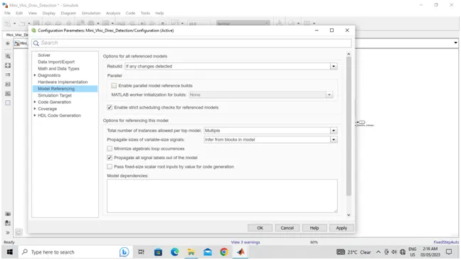
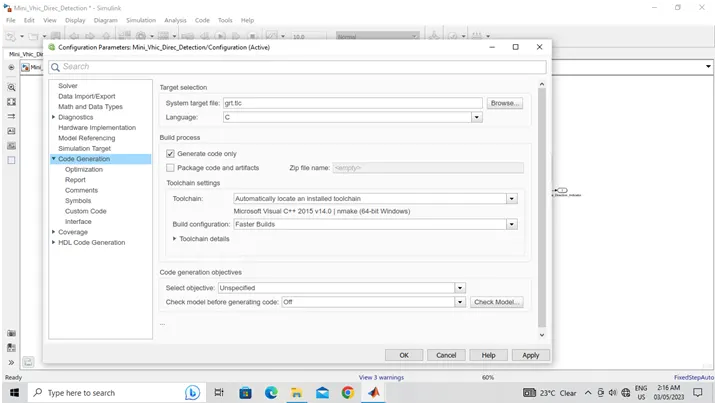
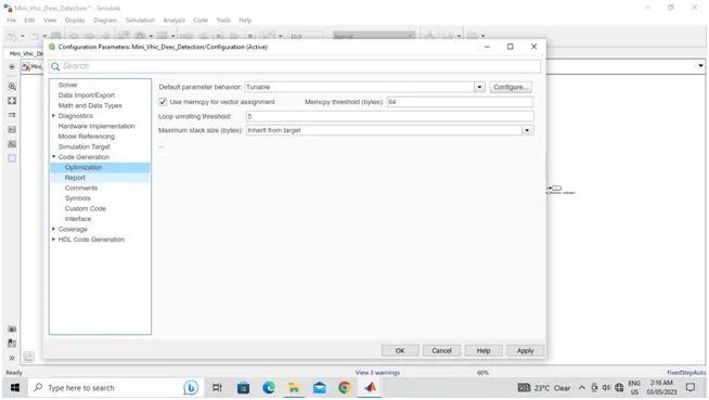
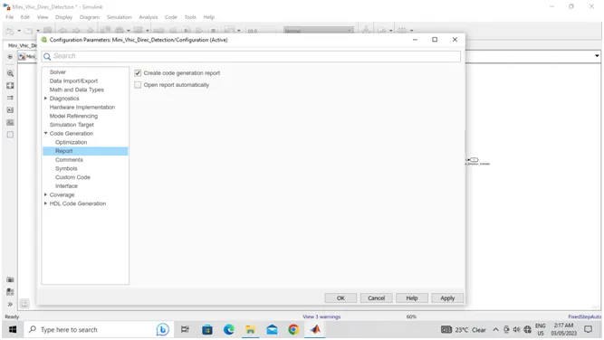
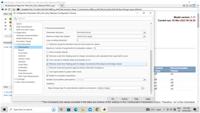
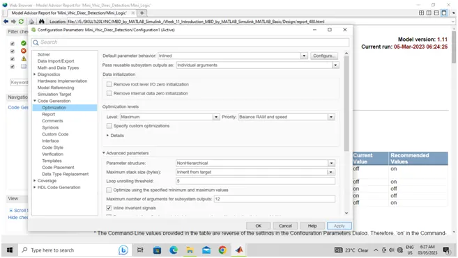
Click on Model Configuration Parameters à Check the Solver and Select the Type of the Solver à Click on Data Import and Export à Click on Diagnosticsà Click on Simulation Target à Click on Code Generation à Click on Coverage Check all the requirements as per the MAAB Guidelines à Click on Apply à Then click on OK.
- As per the Above Screen shot Coverage and Model Advisor reports also generated.
- As the complete process is done and the test cases are analyzed.
- The Test Cases are done in the Excel file as per the given format.
- The file is also attached as *.xlsx file.
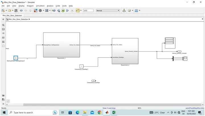
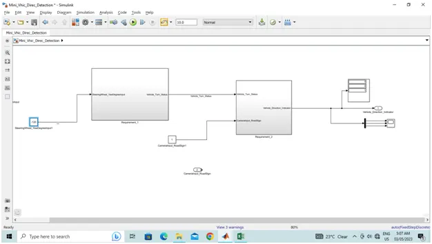
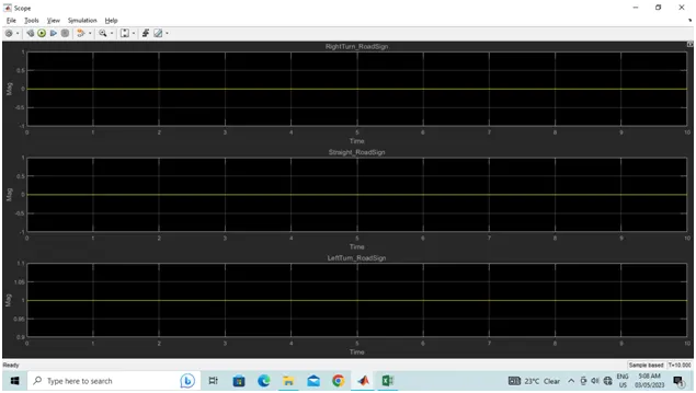
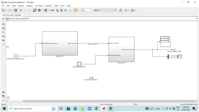
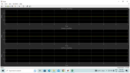
- The system is analyzed creating the inputs by using constant block.
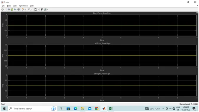
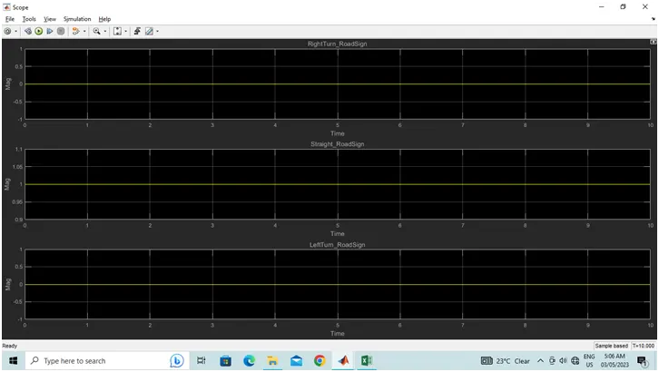
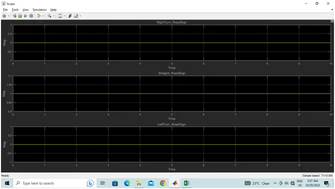
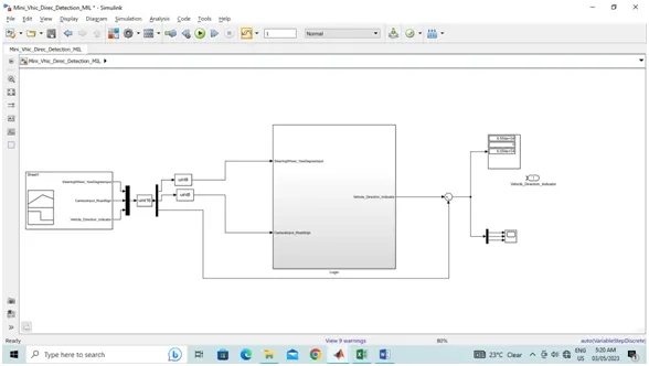
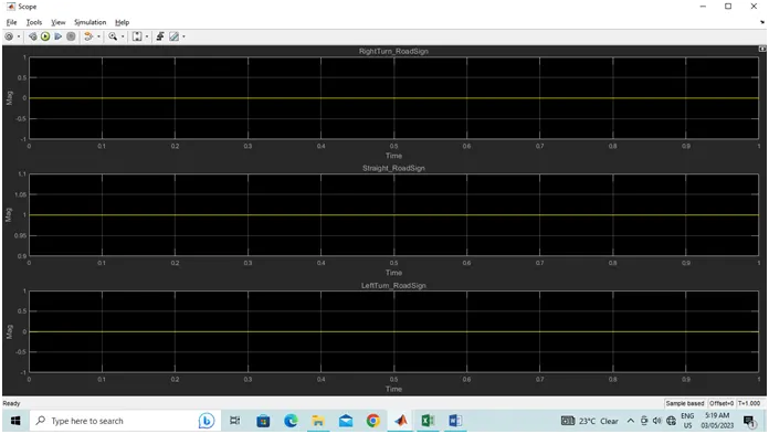
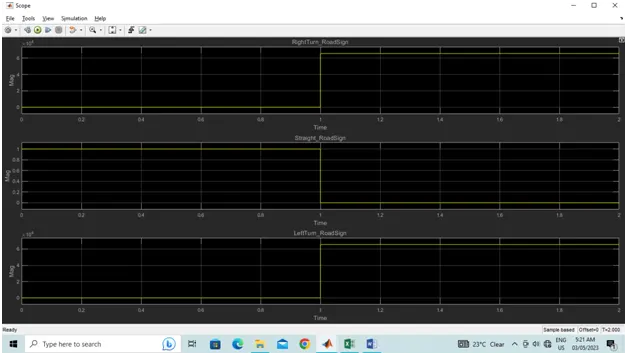
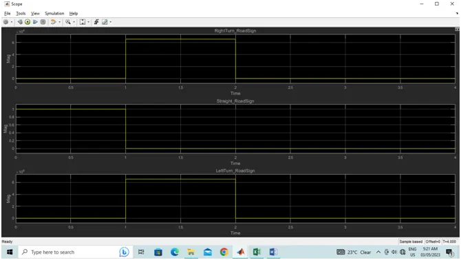
The constant block is saved in sub-system and the output is seen by using Display block (To see in Digital) and Scope block (To see in Graph).
- As per the given file the above is the MIL test Environment.
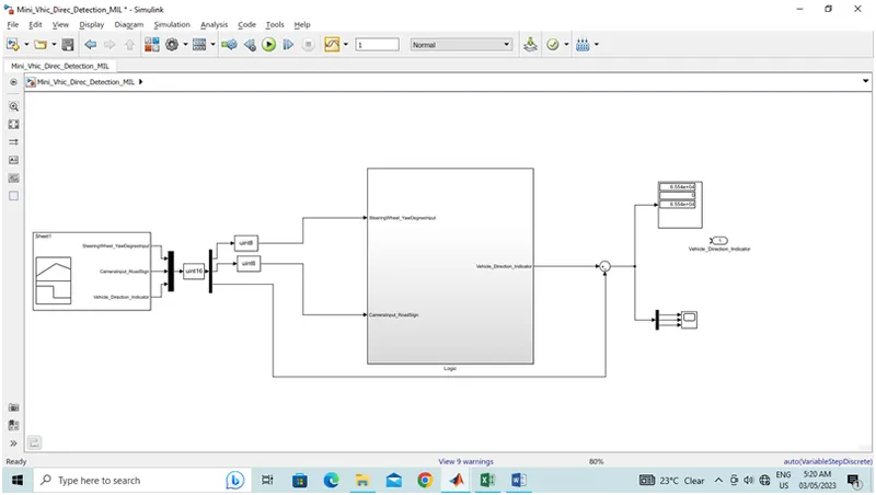
- As per the Above Screen shot Coverage and Model Advisor reports also generated.
- As the complete process is done and the test cases are analyzed.
- The Test Cases are done in the Excel file as per the given format.
- The file is also attached as *.xlsx file.
- The system is analyzed creating the inputs by using constant block.
- The constant block is saved in sub-system and the output is seen by using Display block (To see in Digital) and Scope block (To see in Graph).
- Coverage report is created
- Build the function so that code is generated
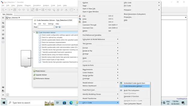
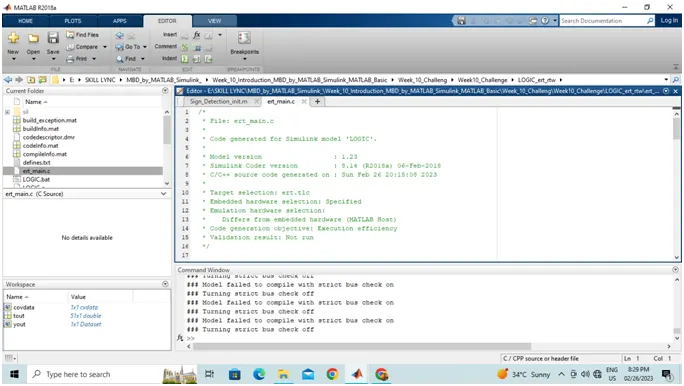
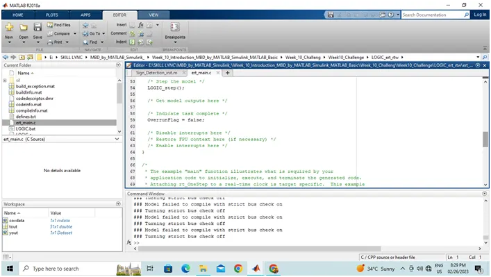
- As per the code generated the generated SIL model by clicking on generate S Function from properties and follow below screen shots for further.
Code:
/*
* File: Mini_Logic.c
*
* Code generated for Simulink model 'Mini_Logic'.
*
* Model version : 1.11
* Simulink Coder version : 8.14 (R2018a) 06-Feb-2018
* C/C++ source code generated on : Sun Mar 5 07:11:33 2023
*
* Target selection: ert.tlc
* Embedded hardware selection: Intel->x86-64 (Windows64)
* Code generation objectives:
* 1. Execution efficiency
* 2. ROM efficiency
* 3. RAM efficiency
* 4. Traceability
* 5. Safety precaution
* 6. Debugging
* 7. MISRA C:2012 guidelines
* 8. Polyspace
* Validation result: Not run
*/
#include "Mini_Logic.h"
#include "Mini_Logic_private.h"
/* External inputs (root inport signals with default storage) */
ExtU_Mini_Logic_T Mini_Logic_U;
/* External outputs (root outports fed by signals with default storage) */
ExtY_Mini_Logic_T Mini_Logic_Y;
/* Model step function */
void Mini_Logic_step(void)
{
int16_T rtb_Switch;
/* Switch: '<S2>/Switch' incorporates:
* Constant: '<S2>/Constant'
* Constant: '<S2>/Constant2'
* Inport: '<Root>/SteeringWheel_YawDegreeInput'
* Switch: '<S2>/Switch1'
*/
if (Mini_Logic_U.SteeringWheel_YawDegreeInput > 30.0F) {
rtb_Switch = Right_Turn_AngularLimit;
} else if (Mini_Logic_U.SteeringWheel_YawDegreeInput >= 0.0F) {
/* Switch: '<S2>/Switch1' incorporates:
* Constant: '<S2>/Constant1'
*/
rtb_Switch = Left_Turn_AngularLimit;
} else {
rtb_Switch = Straight_Drive_Steering_Angle;
}
/* End of Switch: '<S2>/Switch' */
/* Outport: '<Root>/Vehicle_Direction_Indicator' incorporates:
* Constant: '<S4>/Constant'
* Constant: '<S5>/Constant'
* Constant: '<S6>/Constant'
* Inport: '<Root>/CameraInput_RoadSign'
* Logic: '<S3>/Logical Operator'
* Logic: '<S3>/Logical Operator1'
* Logic: '<S3>/Logical Operator2'
* RelationalOperator: '<S4>/Compare'
* RelationalOperator: '<S5>/Compare'
* RelationalOperator: '<S6>/Compare'
*/
Mini_Logic_Y.Vehicle_Direction_Indicator[0] = ((rtb_Switch ==
RightTurn_RoadSign) && (Mini_Logic_U.CameraInput_RoadSign));
Mini_Logic_Y.Vehicle_Direction_Indicator[1] = ((rtb_Switch ==
LeftTurn_RoadSign) && (Mini_Logic_U.CameraInput_RoadSign));
Mini_Logic_Y.Vehicle_Direction_Indicator[2] = ((rtb_Switch ==
Straight_RoadSign) && (Mini_Logic_U.CameraInput_RoadSign));
}
/* Model initialize function */
void Mini_Logic_initialize(void)
{
/* (no initialization code required) */
}
/* Model terminate function */
void Mini_Logic_terminate(void)
{
/* (no terminate code required) */
}
/*
* File trailer for generated code.
*
* [EOF]
*/
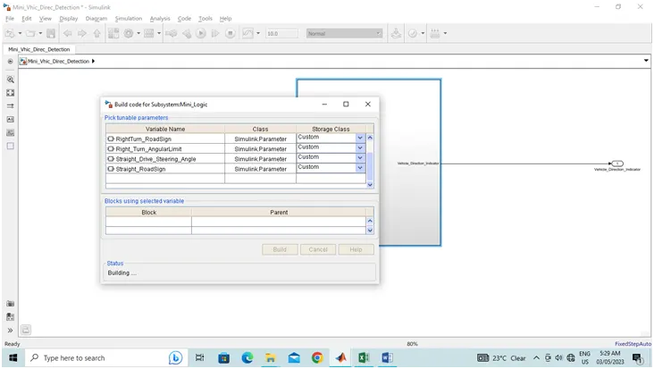
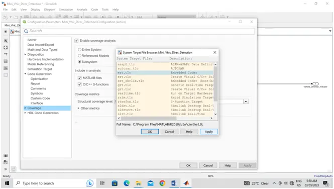
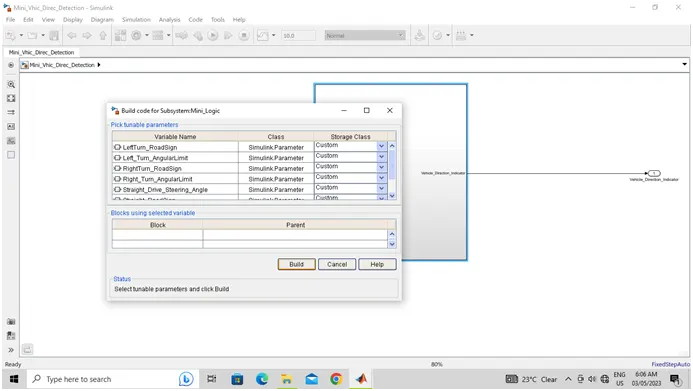
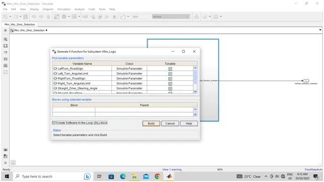
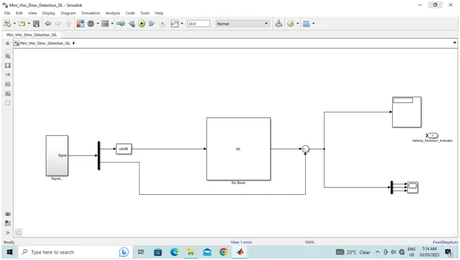
- Then the SIL block is created and it is connected to the input signals and output scopes
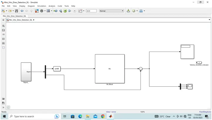
- As per the given file the above is the SIL test Environment
RESULT:
- As per the given Requirement1 and Rquirement2 the Project has designed.
- As per the Above Screen shot Coverage and Model Advisor reports also generated.
- As the complete process is done and the test cases are analyzed.
- The Test Cases are done in the Excel file as per the given format.
- The file is also attached as *.xlsx file.
- The system is analyzed creating the inputs by using constant block.
- The constant block is saved in sub-system and the output is seen by using Display block (To see in Digital) and Scope block (To see in Graph).
- As per the given attachment and question the Model In Loop Test Environment is created
- As per the given attachment and question the Software In Loop Test Environment is created
- The model is created as per the requirements.
- The MIL and SIL template is created and attached.
- Output screen shots are attached.
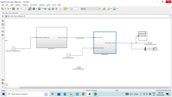
Note: All the files are attcahed